DESIGN AND DEVELOPMENT OF CAPACITIVE POWER TRANSFER SYSTEM
ERNISHA SYUHADA BINTI FAIZUL AZMI
This report is submitted in partial fulfillment of the requirements for the award of Bachelor of Electronic Engineering (Industrial Electronic)
Faculty of Electronic and Computer Engineering Universiti Teknikal Malaysia Melaka
“ I hereby declare that this report is the result of my own work except for quotes as cited in the references.”
Signature :
Author : ERNISHA SYUHADA BINTI FAIZUL AZMI
“I hereby declare that I have read this report and in my opinion this report is sufficient in terms of the scope and quality for the award of Bachelor of
Electronic Engineering (Industrial Electronic) with honours.”
Signature :
ACKNOWLEDGEMENT
In the name of Allah, the Most Gracious, the Most Powerful and the Most Merciful Alhamdulillah, all praises to Allah for the strengths and His blessing in completing this final year project and thesis. I would like take this opportunity to express my grateful who help me and give their courage to me to finish my final year project and thesis as it is partial fulfillment or requirements for the degree of Bachelor in Electronic Engineering (Industrial Electronic).
Special appreciation goes to my supervisor, Pn. Yusmarnita Binti Yusop, for her supervision and constant support. Her invaluable help of constructive comments and suggestions throughout along one year of duration for final year project have contributed to the success of this project.
Sincere thanks to all my friends for give me motivation and boost my effort to finish this project. Thanks for the friendship and memories.
Last but not least, my deepest gratitude goes to my beloved parents; Faizul Azmi Bin Hashim and Mariani Binti Musa for their endless love, prayers and encouragement. To those who indirectly contributed in this project, your kindness means a lot to me.
ABSTRACT
ABSTRAK
TABLE OF CONTENTS
CHAPTER TITLE PAGE
REPORT STATUS VERIFICATION FORM ii
DECLARATION iii
SUPERVISOR CONFIRMATION iv
DEDICATION v
ACKNOWLEDGEMENT vi
ABTRACT vii
ABSTRAK viii
TABLE OF CONTENTS ix
LIST OF TABLES xii
LIST OF FIGURES xiii
I INTRODUCTION
1.1 Introduction. 1
1.2 Objectives of the Project 3
1.3 Problem Statement. 3
1.4 Scope of Project 4
1.5 Project Significant 5
II LITERATURE REVIEW
2.1 Introduction of Wireless Power Transfer 7
2.1.1 The Inductive Power Transfer Method 8 2.1.2 The Capacitive Power Transfer Method 8 2.1.2.1 Coupling Configuration 9 2.1.2.2 Coupling Structure 11
2.2 Introduction of Power Amplifier 12
2.2.1 Class B 12
2.2.2 Class C 13
2.2.3 Class D 14
2.2.4 Class E 15
2.2.4.1 Advantages of Class E 16 2.2.4.2 Class E Configuration 16
2.3 Microcontroller 18
2.3.1 Introduction of PIC 16F877A 18
2.3.2 PWM in Microcontroller 19
III METHODOLDGY
3.1 Project Methodology 21
3.2 Flow Chart Diagram 22
3.3 Gantt Chart 25
3.4 Block Diagram System 26
3.5 Design of Class E MOSFET Converter 27
3.6 Circuit Development 27
3.7 Hardware Development 28
3.9 Hardware and Software Integration 29
3.10 Testing 29
IV RESULT AND DISCUSSION
4.1 Result 30
4.2 Design Microcontroller Circuit 32
4.3 Design High Speed Current Driver Circuit 34 4.4 Design Class E MOSFET Converter Circuit 35
4.5 Coupling Plate 38
4.6 Design Load Circuit 41
4.7 Overall Testing 42
4.6 Discussion 45
V CONCLUSION AND RECOMMENDATION
5.1 Conclusion 47
5.2 Recommendation 48
REFERENCES
LIST OF TABLES
TABLE TITLE PAGE
2.1 CCP Mode 19
3.1 Gantt Chart 25
4.1 Class E MOSFET Converter Specification 35
4.2 Data Analysis for Class E Circuit 38
LIST OF FIGURES
FIGURES TITLE PAGE
1.1 Basic Diagram of Inductive Power Transfer 2 1.2 Basic Diagram of Capacitive Power Transfer 2
2.1 Block Diagram of the CPT System 9
2.2 Configuration of the CPT System 9
2.3 The Structure of Disk Type Cylindrical 11
2.4 The Structure of Coupling 11
2.5 Standard Arrangement for Class B, C and E Amplifier 12
2.6 Waveform of Class-B 13
2.7 Waveform of Class C 13
2.8 The Class-D Amplifier 14
2.9 Waveform for Class-F Amplification 15
2.10 Voltage across Switch and Current through Switch 16 2.11 Single-ended Configuration of Power Amplifiers 17 2.12 Complementary push-pull Configuration of Power Amplifiers 17
2.13 The packaging of PIC 16F877A 18
2.14 Output PWM 19
3.1 Methodology Flowchart 22
3.2 Block Diagram of Capacitive Power Transfer 26 3.3 Main Point of Design Class E MOSFET Converter 27 3.4 The Hardware and Software Integration 29
3.5 The Hardware and Software Testing 29
4.1 The Diagram Wireless Power Transfer Technologies with Using Capacitive Based Method
4.2 Capacitive Power Transfer for Charging Handphone 31
4.3 Microcontroller Circuit in ISIS 32
4.4 Microcontroller Circuit in Ares 32
4.5 Simulation Result for PWM 33
4.6 Measured Result for PWM 33
4.7 High Speed Current Driver Circuit in ISIS 34 4.8 High Speed Current Driver Circuit in ARES 34
4.9 Class E MOSFET Converter Circuit 36
4.10 Simulation Waveform of Class E Circuit 37
4.11 Waveform at Primary Plate 38
4.12 Waveform at Secondary Plate 39
4.13 The Graph of Output Voltage versus Distance between Plates 41
4.14 Charger Circuit in ISIS 42
4.15 The PCB PIC circuit 42
4.16 The PCB High Speed Current Driver circuit 43
4.17 The PCB Class E circuit 43
4.18 The PCB Receiver circuit 43
4.19 The Copper Plates 44
4.20 Charging Application 44
CHAPTER I
INTRODUCTION
1.1 Introduction.
The process of transferring power from one circuit onto another circuit without passing through any manmade conductive elements interconnecting them is the definition for Wireless Power Transfer (WPT). There are several types of wireless power transfer exist such as a microwave, laser, inductive power transfer and capacitive power transfer. For this project is more focuses on capacitive power transfer because due to many advantages.
Figure 1.1: Basic Diagram of Inductive Power Transfer
Figure 1.2:Basic Diagram of Capacitive Power Transfer
IPT is using coil that will produce magnetic field to transfer power while CPT is using capacitive plate that will produce electric field to transfer power. High frequency is needed to generate a magnetic field, usually in 10 kHz to 10MHz in IPT system. This can cause a large electromagnetic interference and magnetic field coupling technology required will depend on easily covered by some metal conductors with small resistance rate. Eddy current losses greater can also be formed, therefore, the IPT technology based on magnetic coupling used in a metal environment is very limited.
[image:15.612.198.489.222.372.2]saturated magnetic fields environment, and capable to decrease electromagnetic interference and energy loss.
This project of design and development of CPT system is planned which involves low values of power transfer in interface capacitance, with lesser power factor than current topologies, and leads to the low power application. In the capacitive interface the field is confined between conductive plates, alleviating the need for magnetic flux guiding and shielding components that add bulk and cost to conductive solution [1].
Capacitive power transfer interfaces makes them very attractive for wireless charging stations and galvanically isolated power supplies because it simplicity and low cost compared to inductive power transfer method. However, conventional capacitive power transfer solutions are widely used either larger capacitors or lower power applications, such as coupling of power and data between integrated circuits or transmitting power and data to biosignal instrumentation systems. This project also, by introducing a self-tuning Class E MOSFET amplifier power converter.
1.2 Objectives of the Project
The objectives of this project are:-
i. To design high efficiency resonant class E inverter.
ii. To generate switching control signal for class E circuit by using PWM technique. iii. To analyze the performance of capacitive power transfer in terms of efficiency
1.3 Problem Statement
A traditional approach of wireless power transfer, the IPT is commonly used. The main drawback of IPT is a very high common mode source impedance to overcome high power factor of current topology that may cause eddy current losses and difficult to penetrate the metal. A priority project is to study how to design a capacitive power transfer system with lower power factor. This involves the low power transmission at the interface capacitance and lead to the low power applications. All weaknesses of IPT can be improved and enhanced using the CPT system.
1.4 Scope of Project
1.5 Project Significant
There are some significant of this project such as this project is very attractive to contactless charging and galvanically isolated power supply and get the spotlight because of the power control and charging device mobile devices including cameras and smart phones. For electromagnetic radiation has less radiation and amenability combined power and data deliver on the same interface. It is also suitable for biomedical device. Maximum efficiency is achieved for a given number of capacitance pairs and used to find the optimal circuit.
1.6 Report Structure
This thesis is a documented report of the ideas generated, the theories and concepts applied, the activities performed and the final product of this project produced. The thesis consists of five chapter is described as follow:-
Capacitive Power Transfer Rectifier Full Bridge Small Power Application Direct Current Supply PIC16F877A Circuit
Class E MOSFETs Converter To supply
12Volt To generate PWM 400 kHz To convert DC to AC Supply
For low power applications such
as charging
To Convert AC
For Chapter 1 will briefly clarify the environment and background of this project. Preliminary with the introduction of this project, that is why this project is important and chosen. Next, this chapter will also explain about the problem statement that generate to the idea to recognize this project. Then, will also explain more about the objectives of the project, scope of work, and also the report structure.
For Chapter 2 will briefly explained about the present theory and concept related to the project. This chapter also discuss about the basic theory of capacitive power transfer system, generate PWM using PIC16F877A and Class E MOSFET converter circuit.
For Chapter 3 will briefly clarify the method to design and develop of the project. This is including the prototype and software design using CCS Compiler, Proteus, Pspice and also Multisim. The hardware development is focus on the designing circuit such as high speed current driver circuit, class E MOSFET converter circuit and microcontroller circuit. The software design focuses on the development of microcontroller instructions coding using CCS Compiler for PIC16f877A.
For Chapter 4 will briefly explain the result for testing method. The construction of capacitive Power Transfer (CPT) will be analysis by measure the output voltage versus distance between primary plate and secondary plate and also the efficiency of the system. Next, the result will be analyze and discuss to get better understanding about the result.
CHAPTER II
LITERATURE REVIEW
In this chapter, the source like journal, thesis and article had been analyzed to come out the comparison to use in this project. This chapter discussed about PWM technique, Class E MOSFET Converter circuit and Capacitive Power Transfer system
2.1 Introduction of Wireless Power Transfer
2.1.1 The Inductive Power Transfer Method
The journal entitled “A Ring Inductive Power Transfer System” was written by Udaya K. Madawala and Duleepa J. Thrimawithana. These journals discuss the design and development of inductive power transfer. The contactless inductive power transfer systems are currently used in many industrial domains, for example elevators, crane and traffic systems. Inductive Power Transfer (IPT) is the technology, which is now recognized as a technique that is efficient and acceptable of contactless power transfer across an air gap through magnetic coupling [2]. IPT system is using magnetic coupling across the air gap without physical contact to transfer power from one system to another system. Tracks leading to the current frequency are high and IPT systems are loosely coupled to magnetic and other systems, also known as the pickup in which power is transferred across the air gap. The magnitudes of the current track directly control. The amount of power that can be transferred across the air gap, and thus plays a major role in the design of any IPT system [2]. A system using high power is better when the track becomes high enough, but unfortunately a semiconductor device at this time is not suitable.
2.1.2 The Capacitive Power Transfer Method
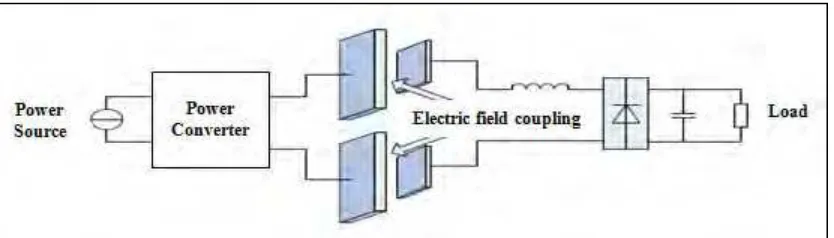
primary and secondary sides, a tuning inductor either series or parallel connection is also usually used to dielectric materials are covered on the surfaces of the plates and recompense the equivalent coupling capacitance.
[image:22.612.122.538.155.299.2]Figure 2.1: Block Diagram of the CPT System
2.1.2.1 Coupling Configuration
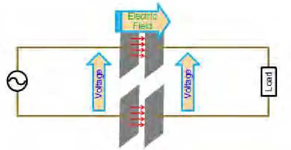
The configuration of the CPT system shows in Figure 2.2. A high frequency AC voltage is converted from the power source which is then supplied to two primary metal plates. Electric fields are formed between them and the displacement current is produced when two secondary plates are placed close. Finally, the power can be transferred without direct electrical contacts. It also allows for some freedom of movement between the primary and secondary plates and supply to the load. A rectifier and capacitor filter can be used, if it is a DC load.
[image:22.612.121.538.576.695.2]Capacitive Power Transfer has many features compared to Inductive Power Transfer: i. The circuit size may be compact because there is no require using bulky and
costly coils and magnetic materials.
ii. The coupling preserve be considered as two capacitors connected in series so power can still pass through, if there is a metal barrier between a pair of coupling plates,. Meaning that CPT has the capability to convey power through metal barriers
iii. Capacitive Power Transfer is using capacitive plate and produce the electric field coupling, and high frequency from kHz to MHz. AC voltage should be functional to the coupling plates
iv. The radiated EMI and the power losses can be significantly compact compared to an IPT system since most electric fields are limited within the volume enclosed in the coupling plates
v. At least two pairs of coupling plates are needed to supply a complete current loop between the power source and the pickup for the complete CPT system.
The formula of equivalent capacitance of each pair of the coupling plates are shown below:
2.1.2.2 Coupling Structure
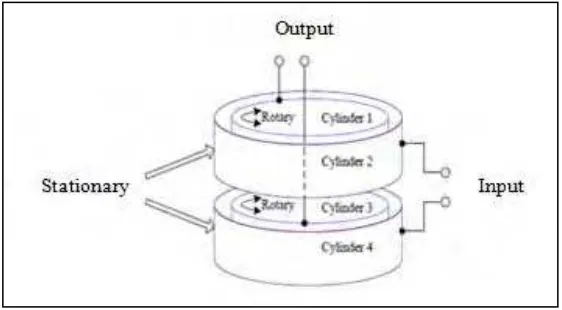
[image:24.612.202.487.319.468.2]The two coupling structures are planned for the necessary rotary application. Consists of two pairs of metal plates in each structure where the coupling distance of each pair is 1mm. Figure 2.3 shows a disk type structure where two disks form one pair of coupling plates and two rings form another. The higher part is rotary and connected to the output load, while the lower part is fixed and connected to the input power source. Next, an extra structure planned is a cylinder type exposed in Figure 2.4 where the cylinders 1 and 2 coupling plate form of one pair and 3 and 4 form another. Two inner ones are rotary and connected to the output load while two outer cylinders are fixed and connected to the input power source.
Figure 2.3: The Structure of Disk Type Cylindrical
[image:24.612.204.485.519.674.2]