Development of Wireless Data Transfer System on Unmanned Underwater
Vehicles Application
1
Aras, M.S.M,
2Ali, F.A.,
3Azis,F.A,
4Abdullah, S.S,
5Aziz, M.A.A,
6M.Nur Othman
1,3Lecturer, Department of Mechatronics, Faculty of Electrical Engineering, Universiti
Teknikal Malaysia Melaka, Melaka, Malaysia.
2,6
Lecturer, Department of Electric and Electronics, Faculty of Technology Engineering,
Universiti Teknikal Malaysia Melaka, Melaka, Malaysia.
4
Senior Lecturer, Department of Electric and Electronics, Malaysia-Japan International
Institute of Technology, Universiti Teknologi Malaysia, Kuala Lumpur, Malaysia.
5
Postgraduate Student, Department of Electric and Electronics, Malaysia-Japan
International Institute of Technology, Universiti Teknologi Malaysia, Kuala Lumpur,
Malaysia
Abstract
This paper presents the development of wireless system for data transfer on unmanned underwater vehicles (UUV) using Xbee Pro 60mWatt. Nowadays, wireless communication technology has become part of our daily life. However, research in underwater wireless communication has been active to design the methods for wireless data transmission underwater. In this system is very important to transfer data from UUV to vessel/platform or other UUV. The technology of underwater wireless communication can be used such as to detect fish or ship, identify the environment at using wireless systems respectively. The microcontroller used in this project is PIC microcontroller that functions as an interface with the computer. Graphical User Interface (GUI) by Visual Basic (VB) software has been used as a way to communicate with the PIC. All the results for data transfer will discuss in this paper.
1. Introduction
Wireless communication is the transfer of information over a distance without the use of enhanced electrical conductors or wire. Wireless communication technology has become part of our daily life [1-2]. The example of wireless communications is a radio frequency, Bluetooth device, Infra-red and wireless fidelity (WI-Fi). However, underwater wireless communication still seems unlikely and still under research [3]. This technology is important to transfer data from underwater vehicles (UV) or vessels to other UV. Throughout this project, a few experiments have been done to study wireless system for data transfer from underwater vehicles [4 – 7].
This project focuses on underwater wireless data transfer. The analysis has been done by using a receiver placed on an underwater glider. This project has been executed underwater that is from a tank filled with water and within line-of-sight (LOS). Another scope is to investigate the range of data transferred that can be received by the receiver by increasing the range of the transmitter and receiver constantly. The accuracy has been measured by verifying between the data transferred and received and the time delay of data transferred has also been observed. Wireless hardware that's been used is XBee Pro 60mW Wire Antenna that can function as a transmitter and a receiver with communication range of 1.5km and XBee Pro Starter Kit that used to connect between XBee and PIC. It uses a PIC microcontroller as an interfacing to computer. The software that has been used is Visual Basic (VB), which used as a way to communicate with the PIC.
Underwater wireless communication is one of the methods used for underwater communication other than using radio wave and optical communication [8 -9]. Wireless communications are established by using acoustic wave. Acoustic communications are governed by three factors that are limited bandwidth, time-varying multipath propagation and low speed of sound underwater [10 -14]. Together these three factors can easily become a factor and influencing of poor quality of wireless communication. Although wireless communication has been studied for years, there are many challenges needed to be overcome by researchers in order for this technology to be used worldwide. A challenging propagation environment and limited understanding of the phenomenon may become tough obstacles to be overcome.
Wireless data transmission is one of the techniques to transfer data from one point to another. However, underwater wireless technology is still under research and the result is still doubtful. It has been proven that radio wave shows poor propagation underwater [15 -16]. Thus, the problem occurs is that whether the Xbee module is capable to send data underwater and whether the data transferred from the transmitter can accurately and precisely receive by the receiver? Another problem is that whether there has been a time delay during the transmission when the range is increasing. This can be solved throughout the LED Range Test in this experiment. Moreover, there is an issue in designing the casing which is to make sure that the casing that contains the wireless receiver is waterproof. This is important so that water did not enter the casing and damages the components inside. Therefore, the usage of an appropriate case for underwater is important so that the casing did not become a resistance to the wireless wave.
2.
Literature Review
XBee is the brand name from Digi International for a family of form factor compatible radio modules as shown in Figure 1. The first XBee radios were introduced under the MaxStream brand in 2005 and were based on the 802.15.4-2003 standard designed for point-to-point and star communications at over-the-air baud rates of 250 kbit/s. Two models were initially
programmable XBee has an additional onboard
processor for user’s code. The programmable XBee and
a new surface mount (SMT) version of the XBee radios were both introduced in 2010 [18]. XBee. XBee Modules typically come with several antenna options, including U.FL, PCB Embedded, Wire, and RPSMA. The Xbee(s) can operate either in a transparent data mode or in a packet-based application programming interface (API) mode. In the transparent mode, data coming into the Data IN (DIN) pin is directly transmitted over-the-air to the intended receiving radios without any modification. Incoming packets can either be directly addressed to one target (point-to-point) or broadcast to multiple targets (star). This mode is primarily used in instances where an existing protocol cannot tolerate changes to the data format [19]. AT
commands are used to control the radio’s settings. In
API mode the data is wrapped in a packet structure that allows for addressing, parameter setting and packet delivery feedback, including remote sensing and control of digital I/O and analog input pins.
Features:
Based on common 802.15.4 XBee footprint, easy to change.
Hardware interface: UART up to 1Mbps, SPI up to 3.5Mbps
Configuration methods: API or AT Commands
Frequency Band: 2.4GHz ISM
ADC input: 4 channels (12-bit)
Digital IO: 10
Antenna: Wire Whip
Wi-Fi Security: WPA-PSK, WPA2-PSK
Channels: 14
Transmit power: > 15dBm
Wireless Range: Up to 120meter (indoor/urban)
Supply Power: +3.1 to 3.6VDC (typical = 3.3V)
Transmit Current: Up to 260mA
Receive Current: 140mA
Power-Down (sleep) Current: <2uA
Wireless LAN Standard: 802.11b/g/n
Data Rate (Configurable): 802.11b up to 11Mbps, 802.11g up to 54Mbps, 802.11n up to 65Mbps
Supports Adhoc and infrastructure networking
Figure 1: Xbee Module
3.
Methodology
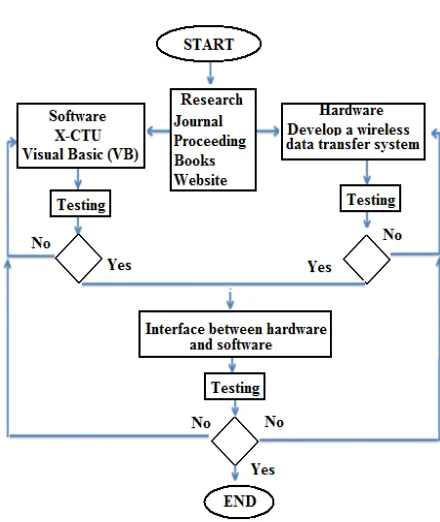
This project starts with a research about wireless data transfer and underwater wireless data transfer. Then a discussion is made with about the hardware and software that are going to be used. Throughout this project, the range, accuracy and time delay of data needed are measured. The system will examine whether a wireless data can be transmitted underwater or not. Table 1 is a project methodology while Figure 2 shows the flowchart of the project.
TABLE 1
PROJECT METHODOLOGY
SOFTWARE HARDWARE
• Programming using X-CTU software for transmission between two points
• Programming using
Visual Basic for interface with PIC
• Use Xbee Pro Starter
Kit and interface with laptop
• Transfer wireless data
between two laptops
• Interface with PIC • Attach to glider
INTERFACE BETWEEN SOFTWARE AND HARDWARE
• Experiment with transferring wireless data
underwater
• Examine the range of data that can be transmitted
from point to point for line-of-sight (LOS)
• Set the range to 100m and increase the range by
100m until 1km
• Tabulate data for accuracy, range and time delay.
Figure 2: Flowchart of project methodology
3.1
The Steps of Testing Operations
XBee Module wireless is a full-duplex types which can function as both transmitter and receiver. On the surface, Xbee Module has been connected to a laptop and Visual Basic (VB) software will function as an interface and GUI. This function as a transmitter Another Xbee Module has been used as a receiver by connecting it with a microcontroller and placed on a glider that can move under water. The software Visual Basic (VB) has been used is a software that can communicate with the microcontroller. The microcontroller used is PIC16F877A.
1. One XBee Module connects to the laptop and the software Visual Basic has been used as an interface as shown in Figure 3.
Figure 3: Connection between XBee Module and Laptop
2. Another XBee module has been connected to PIC and placed inside a sealed box as shown in Figure 4. This will function as a receiver and has been used for underwater during testing. Two LED’s is connected and used as an indicator for making sure all the data transfer successfully.
3. Two types of test have been done that were Range Test and Accuracy Test.
4. During testing, XBee Module that is connected to a laptop will function as a transmitter and another XBee Module inside a sealed box will function as a receiver as illustrate in Figure 5.
5. Range Test has been done by increasing the range between transmitter and receiver and depth of the receiver from the water surface.
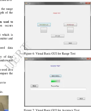
6. In Figure 6 shows two LED’s has been used to indicate if a wireless communication occurs underwater.
7. Accuracy Test is similar to Range Test which is done by increasing the range of the transmitter and receiver as shown in Figure 6.
8. Instead of LED, this test will used data transmission from under water to surface.
9. The purpose is to observe the accuracy of data transferred from one point to another in underwater condition.
10. On the other hand, Visual Basic has been used as a GUI to monitor the data received and compare the accuracy.
11. Each test has been repeated 3 times in order to obtain the average results.
12. All the data has been tabulated and analysis.
.
Figure 4: Sealed box with LED’s used as an indicator
Figure 5: Illustration of wireless communication test
Figure 6: Visual Basic GUI for Range Test
Figure 7: Visual Basic GUI for Accuracy Test
4.
Results
In this chapter, the wireless system unit has been tested and produced the output as expected. The wireless system is divided into two which is a transmitter and receiver. The transmitter will run by USB cable connection with laptop and Visual Basic (VB) has been used as interface. The receiver will run by battery power and connected with PIC16F877A [9]. The results obtained for this project is the information
about the range, accuracy and time delay of the data transmission between transmitter and receiver. The result shows all the information that we want to know before analyzing it for the application on Underwater Vehicles (UV).
Figure 8: Main page of VB interfacing
(a) Green LED testing
(b) Red LED testing
(c) Both LED testing
Figure 9: Data transfer Testing
4.1
Surface and Underwater Range Test
TABLE 2
RANGE TEST 1M TO 10M
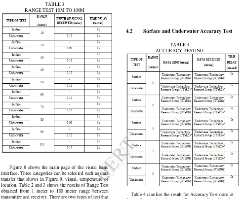
TABLE 3
RANGE TEST 10M TO 100M
Figure 8 shows the main page of the visual basic interface. Three categories can be selected such as data transfer that shows in Figure 9, visual, temperature or location. Table 2 and 3 shows the results of Range Test obtained from 1 meter to 100 meter range between transmitter and receiver. There are two types of test that is surface and underwater. The results also show that the time delay of the data transmission is 0 second. The value is equal to 0 because simple digital clock used to measure this time delay. Almost like zero seconds but if we used high technology digital clock maybe the value is not zero. Almost zero reading. These indicate that the transmission time is very small and very difficult to calculate and analyze. Furthermore, the results demonstrate to users that XBee Module is capable to communicate fast in Line-Of-Sight (LOS) in short range situations [10].
4.2
Surface and Underwater Accuracy Test
TABLE 4 ACCURACY TESTING
Table 4 clarifies the result for Accuracy Test done at the surface and underwater. Based on the table, the result shows similar outcome which is the accuracy is good and there are no losses of data during transmission. Meanwhile, the time delay for this test is 0 seconds which indicate the transmission time is very small and occurs in milliseconds.
Figure 10: Graph of Depth Vs Range (1m to 10m range)
Figure 10 shows the graph of the depth vs. range in the range of 1 meter to 10 meters. The graph explains that at 1 meter range between transmitter and receiver, the maximum depth from the water surface that a receiver can sink is 0.4 meters. A depth further than that leads to the receiver unable to acquire any signal. When the range between transmitter and receiver is increased slightly, the depth of the receiver will decrease slightly that is closer to the surface of water. The results show that range of the transmitter and receiver is inversely proportional to the depth from the surface of water.
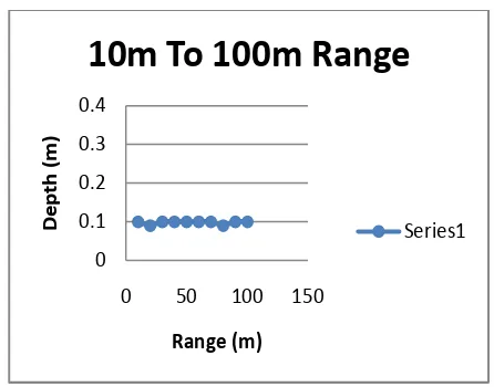
Figure 11 shows the graph of the depth vs. range in the range of 10 meters to 100 meters. The graph explains that the range of the transmitter and receiver is linear to the depth from the surface of water. As the range between transmitter and receiver is increased slightly from 10 meters to 100 meters, the maximum depth from the water surface that a receiver can sink did not change that is approximately 0.1 meters deep. A depth further than that leads to the receiver unable to acquire any signal.
The accuracy of data transmission is studied by taking into account the number of strings received. By referring to Table 4, it shows the results of accuracy test from underwater data transmission. The results illustrate that the accuracy of transmission is good because there are no losses of data in transmission. The data are sent and received are tallied and same. This signifies that whenever a wireless data transmission can occur, the accuracy of data transmission has been good. The only problem here is that to get a signal or to transmit a data, the depth from the surface must appropriate and near to the surface.
Figure 11: Graph of Depth Vs Range (10m to 100m range)
After all the tests have been done and analyze, it has come to a point that XBee module is capable to be used for underwater wireless data transmission. Based from the Range Test completed, wireless communication from under water to surface is proper to be made for short distances between transmitter and receiver. This is because of at short distance, the strength of transmitter signal is higher thus the receiver can be placed lower from the water surface. However, the maximum depth for a receiver to be positioned from water surfaces is approximately 0.4 meters. The reasons for this situation is because the signal strength is lower when the receiver is submerge lower than the water surface and noise or resistance during transmission from under water to surface.
Meanwhile, the accuracy results for underwater data transmission shows good outcome. The number of string type data that has been sent is accurately read by the receiver. The caused for such result is affected by the time delay. Since the time delay for data transmission is very fast that is in millisecond, the data send can precisely be read fast enough even though the signal strength is low.
5.
Conclusion
In conclusion, all the objectives for this project are achieved. A wireless system for data transfer from underwater vehicle application has been developed by using the XBee wireless module as a receiver and transmitter antenna. This application is suitable to be used to send data from underwater vehicles to surface in short distance only that is about 100 meter distance between transmitter and receiver. The range, accuracy and time delay for underwater wireless data transfer has been studied and can be applied to underwater vehicles.
In summary throughout this project, a wireless data transmission for underwater vehicles can only be performed at the level of water surface. There are a lot of improvements that can be made before the XBee wireless module is fully appropriate for the application for Underwater Vehicle (UV). But underwater wireless data transmission by using the XBee wireless module is capable of sending and receiving data in short distance accurately, thus make it suitable for the application on underwater vessel.
Suggestions for this project in the future planning are to design an antenna for underwater application. This may overcome the problem of short range between transmitter and receiver of data transmission. The antenna designed must be capable of receiving even the lowest wireless signal from underwater. Wireless module other than an XBee can also be studied to differentiate its capabilities to use for underwater applications. Moreover, issue in experimental design can also be upgraded and studied to reduce the noise and resistance to the wireless signal.
Acknowledgment
We wish to express our gratitude to the University (Universiti Teknikal Malaysia Melaka - UTeM) especially to Faculty of Electrical Engineering and Centre for Research and Innovation Management (CRIM) for giving the financial as well as moral support to complete this project successfully.
References
[1] MSM Aras, MKA Rahim, Z Rasin, MZA Abdul Aziz, An array of a dielectric resonator antenna for wireless application, IEEE International RF and Microwave Conference, 2008. RFM 2008, Pages 459-463, 2008.
[2] MSM Aras, MKA Rahim, A Asrokin, MZA Abdul Aziz, Dielectric resonator antenna (DRA) for wireless application, IEEE International RF and Microwave Conference, 2008. RFM 2008. Pages 454-458.
[3] Zulhani Rasin, Hizzi Hamzah, Mohd Shahrieel Mohd Aras, Application and evaluation of high power ZigBee based wireless sensor network in water irrigation control monitoring system, . IEEE Symposium on Industrial Electronics & Applications, 2009. ISIEA 2009 Volume 2 Pages 548-551.
[4] M S.M Aras, H. A. Kasdirin, M. H. Jamaluddin, M. F. Basar, Design and Development Antonomous Underwater Vehicle (AUV-FKEUTeM), Malaysian Technical Universities Conference on Engineering and Technology 2009 (MUCEET 2009), Kuantan, Pahang.
[5] M S.M Aras, H. A. Kasdirin, M. H. Jamaluddin, Design
and Development of the Multi-Input Sensor Algorithm for Autonomous Underwater Vehicle (AUV-FKEUTeM), World Engineering Congress 2010 (WEC 2010), Kuching Sarawak.
[6] M.S.M.Aras, M.H.Harun, M.Mohamad, Design and Development of the Multi-Input Sensor Algorithm for Autonomous Underwater Vehicle Stage 2, 2nd international Conference on Technology & operations management (ICTOM 2010), Langkawi.
[7] MSM Aras, FA Azis, MN Othman, SS Abdullah, A Low Cost 4 DOF Remotely Operated Underwater Vehicle Integrated With IMU and Pressure Sensor, 4th International Conference on Underwater System Technology: Theory and Applications (USYS'12). Malaysia Pages 18-23.
[8] James P., Milica S., Michele Z. Guest Editorial Underwater Wireless Communication Networks. IEEE Journal. 2008.
[9] Lanbo L., Shengli Z., Jun-Hong C. Prospects and Problems of Wireless Communication for Underwater Sensor Networks. Wiley WCMC (Issue on Underwater Sensor Networks).
[10] Nicopolitidis P., Pomportsis A. S., Vol. 35, No. 3.
Adaptive Data Broadcasting in Underwater Wireless Networks. IEEE Journal of Oceanic Engineering. July 2010.
[11] Jung-Woo H., Hyung-Jun J., Ki-Man K., Seung-Yon C. A Study on the Cooperative Diversity Technique with Amplify and Forward for Underwater Wireless Communication. IEEE Journal of Oceanic Engineering. 2008.
[12] Farizah Y., Sharifah H. S. A., Yasser Z. A Survey of Existing Medium Access Control (MAC) for Underwater Wireless Sensor Network (UWSN).IEEE Journal. 2010.
[13] Soonchul P., Bonggyun J., Dong S. H. An Efficient MAC Protocol for Data Collection in Underwater Wireless Sensor Network. IEEE Journal. 2009.
[14] Abdul H. F., Rozeha A. R., Norsheila F. Development of IEEE802.15.4 based WirelessSensor Network Platform for Image Transmission. IEEE Journal.
[15] SKXbee User`s Manual. Cytron Technologies (2010).
[16] Xbee datasheet. Digi Technologies (2010).
IJERT
[17] PIC16F877A User`s Manual. Cytron Technologies (2010).
[18] Lloyd B., Underwater Radio Communication. http://www. qsl. net /vk5br/ UwaterComms.html
[19] Hong-bo X., Jiang P., Kai-hua W. Design of Water Environment Data Monitoring Node Based on ZigBee Technology. IEEE Journal of Oceanic Engineering. 2009.