CHAPTER 1
INTRODUCTION
1.1 INTRODUCTION
Nowadays car is the most important transport for people. Car is an
Cellular mobile phone is the most important things for people nowadays. People can keep on communicate without range limit. . The use of harmonised spectrum across most of the globe, combined with GSM’s international roaming capability, allows travellers to access the same mobile services at home and abroad. Short message service is a mechanism of delivery of short messages over the mobile networks. People can send short messages to any other GSM mobile user around the world without limitation using GSM. Real-time monitoring and fast-accurate alarm system have gained popularity among car user and had been widely been applied in order t maximize the effectiveness of the car security system.
Because of it unlimited range of distance, car monitoring can be done using GSM. Using GSM module it can acts as the medium of interfacing between alarm system and wireless communication system and it is also an advantage of the alarm system. The blend of GSM technology and car security system will make the alarm is the best protection mechanism for the vehicle.
1.2 PROBLEM STATEMENT
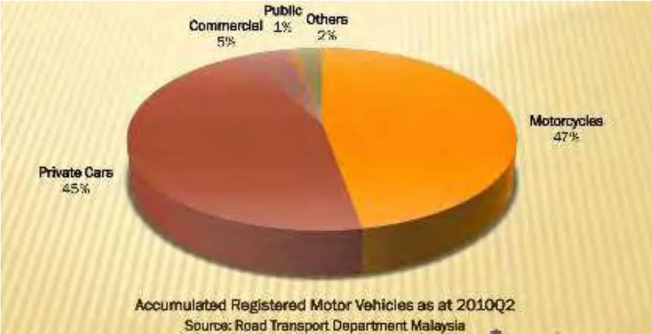
Figure1.1: Total Vehicle on the Road
[image:3.595.113.571.101.336.2]
The effects of theft are raise the quantity claim insurers paying, produces other violent crimes, consumer do not aware choosing stolen vehicles from the car seller and extra. This can be preventing by utilizing the improved locking system to the automobiles. Most common improved locking equipment is GSM/GPS built securing system along with the users could just fix it in the vehicles so they may locate their vehicles from any location so this method also will likely be useful for the police to track the vehicle.
Most of the transportation owners require an effective, reliable and also cost effective product to protect their vehicle. This type of product typically desired several characteristics for example sensors and also alarm triggering which is likely to be more efficient if the technique installed a GSM or GPS module onto it. Therefore, within this project, an automobile security monitoring system designed to stay away from the decrease of assets in Malaysia. Even though, it is just a simplex connection however ii is more efficient, reliable, user friendly and cheaper than other simplex security system in market place.
Security system is important to protect the car from theft and others bad elements. It is hard for the owner to monitor and protect their vehicles from far. Most of the car security system is not a good feedback features. It has a small range limitation between car and the owner. With the small limitation range, the system is not effective security system.
1.3 OBJECTIVE OF PROJECT
To have an objective is important in order to achieve the desired output. There is a few objective need to be determined followed as a guide through the whole completion process of this project.
Develop a notification security system that can wrap the entire main parts of the vehicle and send messages to the users instantly using GSM.
1.4 SCOPE OF PROJECT
Scope of project is important to achieve the objective of the project, there are several scopes that have been outlined. The scopes of the project are:
I. To make the circuit of the microcontroller and the GSM model. II. To design coding for the microcontroller
III. To simulate and analyze the system
1.5 METHODOLOGY
Figure 1.3: Project flow chart
The first phase of project is literature review, where the research part starts. This phase comprises the research using multiple resources such as articles journal papers, thesis and reference books obtained from university library, online and newspapers. Then, the idea to design the project and the features of the device obtained.
The second phase of the project is the design of block diagram. The design comprises of the components used and it shown on figure 1.4. The components comprises of power supply, voltage regulator, sensors (door, vibration, motion, key), LCD, PIC16F877A, buzzer, MAX232 and GSM Modem. The function of the components in the block diagram explained below
Power Supply
Voltage Regulator
The function is to regulate voltage and will supply only 5 V to other components in the circuit
MAX232
This component is a specialized circuit to make standard voltage RS 232 standard require.
Vibration Sensor
Detect force entry by the thieves and this device provide internal and external defense parameter
Door Sensor
Sensor is used to detect whether the door open or close.
Key Sensor
The sensor at the key part when the alarm will activated when someone try break in and start the engine.
Buzzer
Buzzer or alarm will activate when the vibration sensor mode is on.
LCD
The sensing mode will display on LCD.
GSM
Figure 1.4: Block Diagram of the System
The third stage is hardware implementation, which the hardware constructed and also development done by using the MULTISIM application also circuit debugging began. The hardware is examined and also connectivity checking as well completed. The hardware part comes with microcontroller, MAX232, sensing unit, LCD and also GSM unit. A microcontroller is a perfect-designed computer system on a microchip also has various features, such as input/output peripheral, storage and the processor core. MAX232 is RS232 level converter, which will converts the RS232 level into 0V and 5V.
door is open or close as well as the key sensor utilized to detect the car engine activation, where it is connected to the starter and it enable sending powerful electric source to start the car. The LCD shows two rows of 16 character types also utilized to show the form of sensor activated of the hardware designed. The GSM executes over a owner to a cellular operator by using sim card. In this project, the GSM utilized to send out the information of the sensing unit sensed as the messages to the user’s cell phone.
The fourth phase is the software program implementation, whereas the algorithms of the whole equipment design also functionality written using PCW application. PCW software is commonly used and provides an overall, integrated tool for debugging and developing programs for PIC microcontrollers. This type of encoding progression tool has an intelligent code optimizing C compile. Therefore, it contributes greatly to the software developer to focus on the design features as well as features rather than concentrate on the MCU structure. This application also maximizes the code reuse and minimizes the lines of new code with the integrated features, standard C operators and also peripheral drivers. The built-in library allows the PIC to access directly the hardware functions, which working with C language.
1.6 Summary
In this project, in able to complete the task and the objective, many steps we have done according to the fixed steps. The tasks need to be accomplished and complete to the weekly timeline project duration. In the meantime, in the
CHAPTER 2
LITERATURE REVIEW
2.1 Introduction
In this chapter, it contains the past and present other studies related to the projects of Development of GSM Based for Car Security System. Just before to make a first step of the project, the related projects and works that available in the market will be consider carefully. It is important to generate a product that is cheaper and convenient to the consumer.
Literature review and theoretical knowledge studies will be carried out due to the complete of project. The steps have to be done to fully understanding and
innovative skills to successfully complete the project. There are useful for the
All characteristic of the project related were analyzed thoroughly to gain better understanding of present needs of the consumer in overall aspect like safety and money. Hence, characteristic identified to implement this task or essential features research. The parameters of the studies and projects that have done by other researchers were also given attention to prevent errors.
2.2 Review of Past and Present Projects
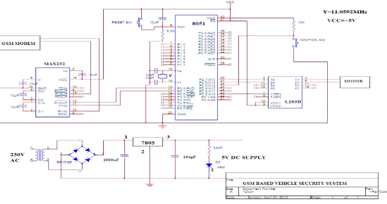
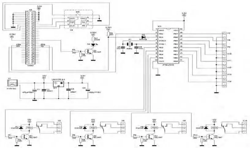
“GSM Based Vehicle Security and Monitoring System”, Muhammad Ali mazidi,Janice gillispie mazidi, Kenneth j.Ayala, Ramesh s.gaonkar, D.V.Prasad, Lawrence Harte (Thesis)
The project was to design and create a car security and monitoring system based on GSM technology. The project design contains the GSM modem and microcontroller which based on the controlling unit. The system will automatically locks the car when received message from the owner. Whenever the owner decided to start the car, the owner has to turn on the ignition switch. The predefined message will send to the owner when the switch is pressed and the microcontroller has detected the switch. Hence, the owner has the overall control of the car in his hand. The system in this project consist such as crystal circuit, MAX 232, ignition switch, reset circuitry, microcontroller, driver circuit, motor, ignition switch and GSM modem.
Figure 2.1: Circuit Design Diagram
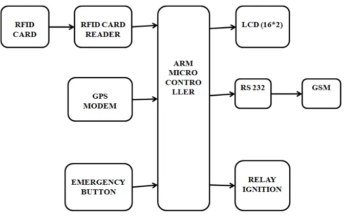
“GPS and GSM Based Vehicle Tracing and Employee Security System” by S S Pethakar, N Srivastava and S D Suryawanshi-JANUARY2013 (Journal)
Figure 2.2: Block Diagram of the System
[image:14.595.113.449.66.280.2]
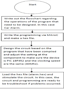
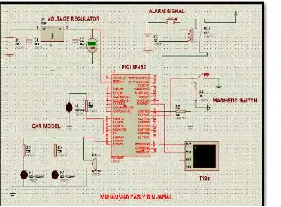
“Car Security Control System via SMS” Muhammad Fazly Bin Jamal MAY2008 (Thesis)
Figure 2.4: System Flowchart
Figure 2.5: Circuit diagrams
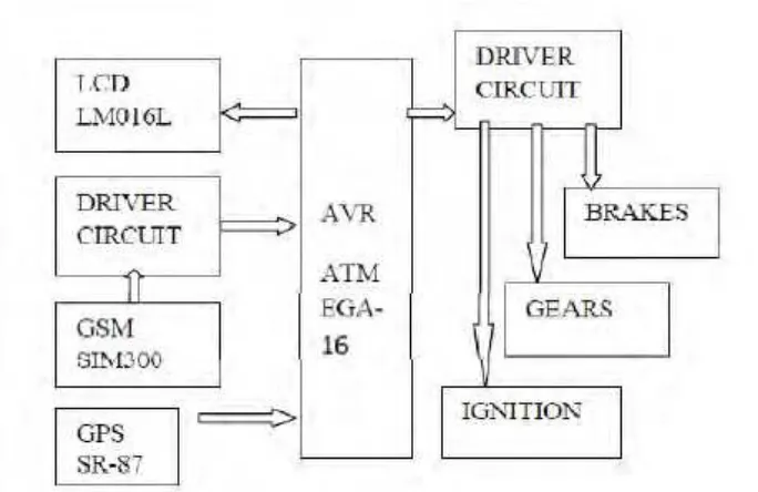
“Design of A GSM Cell-Phone Based Vehicle Monitoring& Theft Security System” by Amol S. Dhotre, Abhishek S. Chandurkar & S. S. Jadhav (Journal)
Figure 2.6: Block Diagram of the System
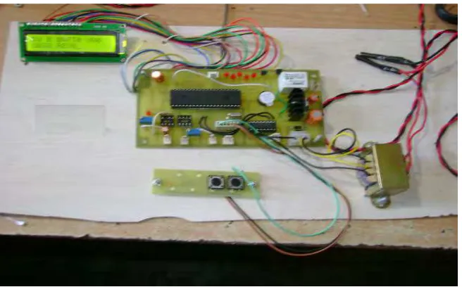
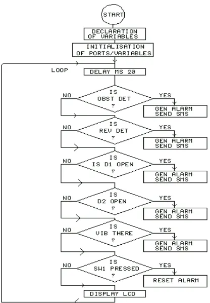
“GSM Based Car Security System” by Ruchita J. Shah, Anuradha P. Gharge October 2012(Journal)
Figure 2.7: Circuit block diagram
Figure 2.8: System hardware
[image:19.595.156.484.363.567.2]Figure 2.9: Flowchart of the system
Desig of “M“-E a led Car “e urity “yste y K.A. Amusa, O.O.Muga, A.A.Adetomi-
NOVEMBER2012 (Journal)
Figure 2.10: System Hardware Circuit Diagram
2.3 Communication System
Communications is sending of information from one place to another place. In communication there are two ways of communications, either primitive or
Figure 2.11: Basic Communication System Diagram
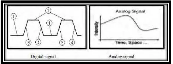
2.4 Signals type
Transmitter will transmits any data information in the form such as image, music, video, and also data. There are two types of signal divided consists which are digital signal and analog signal. The digital signal also known as discrete signal and consist discrete number of level. While the analog signal have a difference amplitude values and changes in constant range. Figure below will show the type of signals.
[image:22.595.188.486.529.640.2]2.5 Microcontroller
Microprocessor has no RAM, ROM and other peripheral on the chip; it has only the CPU (Central Processing Unit) inside them. On the other hand, microcontrollers are designed to perform specific application, where the input and output is defined.
[image:23.595.198.442.349.520.2]A microcontroller is a perfect-designed computer system on a chip .The microcontroller has various features, such as input/output peripheral, memory and processor core. The memory, CPU (Central Processing Unit) and other peripherals of input/output are not in the features of microcontroller.
Figure 2.13: Microcontroller
will reduce the labour needed for assembling purposes and examining the printed circuit board [3].
[image:24.595.171.466.275.541.2]The microcontroller that was used in this project is PIC 16F877A,where is it commonly find, easy to use and comprises of 40 port pins, which are used for modification and features development of the vehicle security system. Figure 2.14 and 2.15 shows the operating pins of IC and PIC16F87XA features for PIC 16F877A [2].