STRUCTURAL DESIGN OF CIBUBUR APARTMENT
JAKARTA
Final Project
By:
YOHANES MEDISA PENTA KHARISMA Student Number: 04 13 11910
ATMA JAYA YOGYAKARTA UNIVERSITY FACULTY OF ENGINEERING
DEPARTMENT OF CIVIL ENGINEERING INTERNATIONAL S1 PROGRAM
iv
PREFACE
First and foremost, I would like to thank God for His blessing that has been given to me, so that I could prepare and finish this final project report. This report was arranged, due to finish the S1 degree at Faculty of Engineering, Department of Civil Engineering, Atma Jaya University Yogyakarta.
In this final project, Structural Design of Cibubur Apartment Jakarta, I would like express my appreciation to:
1. Dr. Ir. Ade Lisantono, M.Eng., as the Dean of Engineering Faculty, University of Atma Jaya Yogyakarta.
2. Prof. Ir. Yoyong Arfiadi, M.Eng.,PhD as the advisor of final project who has given guidance during this final project was arranged.
3. Ir. Y. Lulie, M.T., as the Head of International of Civil Engineering of Atma Jaya Yogyakarta University.
4. Ir. Junaedi Utomo, M.Eng., as the head of Civil Engineering Department, University of Atma Jaya Yogyakarta.
5. Mas Wiko, as the administration staff of Civil Engineering International Program, University of Atma Jaya Yogyakarta who has given information about the administration requirements.
6. My Family who always supports, praises and gives motivation with unlimited time and conditions
7. All of my friends who have supported and given motivation to the author.
I realized that, this report has some mistakes maybe, but I trust all critics from all of you can make it better. Finally I hope this report could give advantages for the readers.
Yogyakarta, August, 2011
v
CONTENTS
TITLE ... i
APPROVAL SHEET I ... ii
APPROVAL SHEET II ... iii
PREFACE ... iv
CONTENTS ... v
TABLE CONTENTS ... ix
FIGURE CONTENTS ... x
APPENDIX CONTENTS ... xi
ABSTRACT ... xii
CHAPTER I. INTRODUCTION ... 1
1.1. General Background ... 1
1.2. Problem Statement ... 2
1.3. Limitations ... 2
1.4. Objectives ... 3
CHAPTER II. LITERATURES REVIEW ... 4
2.1. Loading ... 4
2.2. Ductility ... 4
vi
2.2.2. Ductility Level ... 5
2.2.3. Basic of ductility Level Selection ... 6
2.3. Concrete Slab ... 6
2.4. Beam ... 7
2.5. Column ... 7
CHAPTER III. BASIC THEORIES ... 9
3.1. Loading Analysis ... 9
3.1.1. Required Strength (U) ... 9
3.1.2. Design Strength ... 10
3.2. Earthquake Design ... 12
3.2.1. Static Equivalent Analysis ... 13
3.2.2. Dynamic Response Analysis ... 16
3.2.3. Spectrum Response Modes Analysis ... 17
3.2.4. Service Limit ... 18
3.2.5. Ultimate Limit ... 18
3.3. Slab Design ... 18
3.3.1. One-way Slab ... 19
3.3.2. Two-way Slab ... 20
3.3.3. Reinforcement ... 21
3.4. Stair Design ... 23
3.5. Beam Design ... 23
vii
3.5.2. Longitudinal Reinforcement ... 25
3.5.3. Transversal Reinforcement ... 27
3.5.4. Design Shear Force ... 27
3.5.5. Torsion Design ... 29
3.6. Column Design ... 31
3.6.1. Column Design Limitation ... 31
3.6.2. Check Slenderness Effect of Column ... 32
3.6.3. Flexure of Column ... 32
3.6.4. Longitudinal Reinforcement ... 33
3.6.5. Transversal Reinforcement ... 35
3.6.6. Design Shear Force ... 35
3.6.7. Beam-Column Connection ... 36
CHAPTER IV. STRUCTURAL ELEMENT DESIGN ... 38
4.1. Structural Elements Estimation ... 38
4.1.1. Thickness Estimation for Slab ... 38
4.1.2. Dimension of Beam ... 47
4.1.3. Nominal Load Estimation for Each Floor ... 50
4.1.4. Dimension of Column ... 51
4.2. Slab Design ... 59
4.3. Stair Design ... 75
4.4. Earthquake Loading ... 89
viii
4.5.1. Flexural Reinforcement ... 102
4.5.2. Moment Capacity ... 114
4.5.3. Shear Reinforcement ... 121
4.5.4. Torsion Reinforcement ... 124
4.6. column Design ... 126
4.6.1. Slenderness of column ... 126
4.6.2. Longitudinal Reinforcement ... 130
4.6.3. Flexure of Column ... 135
4.6.4. Transversal Reinforcement ... 137
4.6.5. Design Shear Forcce ... 139
4.6.6. Beam-Column Connection ... 142
CHAPTER V. CONCLUSION AND SUGGESTION ... 147
5.1. Conclusion ... 147
5.2. Suggestion ... 148
REFERENCES ... 150
ix
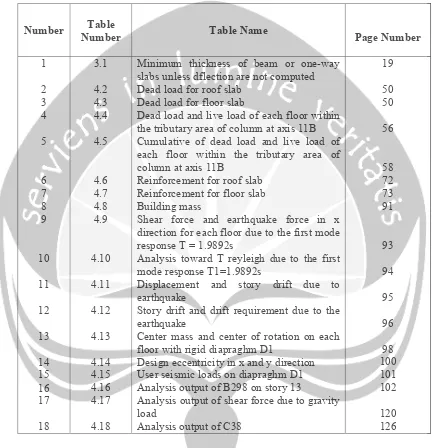
TABLE CONTENTS
Number Table
Number Table Name Page Number
1
Minimum thickness of beam or one-way slabs unless dflection are not computed Dead load for roof slab
Dead load for floor slab
Dead load and live load of each floor within the tributary area of column at axis 11B Cumulative of dead load and live load of each floor within the tributary area of column at axis 11B
Reinforcement for roof slab Reinforcement for floor slab Building mass
Shear force and earthquake force in x direction for each floor due to the first mode response T = 1.9892s
Analysis toward T reyleigh due to the first mode response T1=1.9892s
Displacement and story drift due to earthquake
Story drift and drift requirement due to the earthquake
Center mass and center of rotation on each floor with rigid diapraghm D1
Design eccentricity in x and y direction User seismic loads on diapraghm D1 Analysis output of B298 on story 13
Analysis output of shear force due to gravity load
Analysis output of C38
x
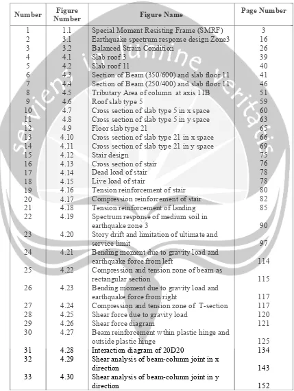
FIGURE CONTENTS
Number Figure
Number Figure Name
Page Number
1
Special Moment Resisting Frame (SMRF) Earthquake spectrum response design Zone3 Balanced Strain Condition
Slab roof 3 Slab roof 11
Section of Beam (350/600) and slab floor 11 Section of Beam (250/400) and slab floor 11 Tributary Area of column at axis 11B Roof slab type 5
Cross section of slab type 5 in x space Cross section of slab type 5 in y space Floor slab type 21
Cross section of slab type 21 in x space Cross section of slab type 21 in y space Stair design
Cross section of stair Dead load of stair Live load of stair
Tension reinforcement of stair Compression reinforcement of stair Tension reinforcement of landing Spectrum response of medium soil in earthquake zone 3
Story drift and limitation of ultimate and service limit
Bending moment due to gravity load and earthquake force from left
Compression and tension zone of beam as rectangular section
Bending moment due to gravity load and earthquake force from right
Compression and tension zone of T-section Shear force due to gravity load
Shear force diagram
Beam reinforcement wthin plastic hinge and outside plastic hinge
Interaction diagram of 20D20
Shear analysis of beam-column joint in x direction
xi
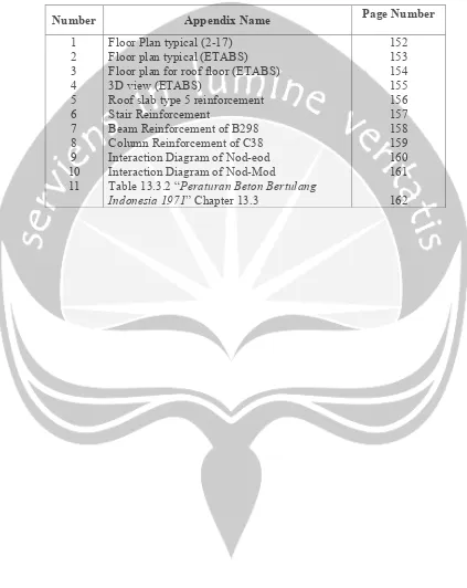
APPENDIX CONTENTS
Number Appendix Name Page Number
1 2 3 4 5 6 7 8 9 10 11
Floor Plan typical (2-17) Floor plan typical (ETABS) Floor plan for roof floor (ETABS) 3D view (ETABS)
Roof slab type 5 reinforcement Stair Reinforcement
Beam Reinforcement of B298 Column Reinforcement of C38 Interaction Diagram of Nod-eod Interaction Diagram of Nod-Mod
Table 13.3.2 “Peraturan Beton Bertulang
Indonesia 1971” Chapter 13.3
xii
ABSTRACT
STRUCTURAL DESIGN OF CIBUBUR APARTMENT JAKARTA, Yohanes Medisa Penta Kharisma, Student Number: 041311910, International Civil Engineering, Atma Jaya Yogyakarta University.
In Structural design safety and economical aspect are very important, therefore some building codes i.e, “Tata Cara Perhitungan Struktur Beton untuk
Gedung” SNI 03–2847–2002 and “Tata Cara Perencanaan Ketahanan Gempa
untuk Bangunan Gedung” SNI 03–1726–2002 will be used as references in
structural design.
Building which has been designed is 18 stories building where it is located in earthquake zone 3, therefore full ductility as ductility level and Special Moment Resisting Frame system are considered in design. Structural analysis by using ETABS v 9.07. and according to codes as mentioned at above, which the structure itself is modeled as 3 dimensional building.
From structural design result, the entire slab has the thickness 120 mm most of them are designed as two-way slab and some designed as one-way slab with reinforcement bar 10 mm. Stair has the thickness 150 mm, with reinforcement bar 10 mm. Dimension of beam B298 at story 14 is 350x600, longitudinal reinforcement for support area are 6D20 (top reinforcement), 4D20 (bottom reinforcement), longitudinal reinforcement for midspan area are 4D20 (top reinforcement), 4D20 (bottom reinforcement). Dimension of column C38 at story 14 is 600x600 mm, longitudinal reinforcement has 20D20, and transversal reinforcement has P10 – 100.