UNIVERSITI TEKNIKAL MALAYSIA MELAKA
DESIGN AND FINITE ELEMENT ANALYSIS OF HIP JOINT
PROSTHESIS
This report submitted in accordance with requirement of the Universiti Teknikal Malaysia Melaka (UTeM) for the Bachelor Degree of Manufacturing Engineering
(Manufacturing Design) with Honours.
by
MOHD NORHISHAMUDIN BIN MOHAMED AZLANUDIN
B050810203
UNIVERSITI TEKNIKAL MALAYSIA MELAKA
BORANG PENGESAHAN STATUS LAPORAN PROJEK SARJANA MUDA
TAJUK: DESIGN AND FINITE ELEMENT ANALYSIS OF HIP JOINT PROSTHESIS
SESI PENGAJIAN: 2010/ 11 Semest er 2
Saya MOHD NORHISHAMUDIN BIN MOHAMED AZLANUDIN
mengaku membenarkan Laporan PSM ini disimpan di Perpust akaan Universit i Teknikal Malaysia Melaka (UTeM) dengan syarat -syarat kegunaan sepert i berikut :
1. Laporan PSM adalah hak milik Universit i Teknikal Malaysia Melaka dan penulis. 2. Perpust akaan Universit i Teknikal Malaysia Melaka dibenarkan membuat salinan unt uk
t uj uan pengaj ian sahaj a dengan izin penulis.
3. Perpust akaan dibenarkan membuat salinan lapor an PSM ini sebagai bahan pert ukaran ant ara inst it usi pengaj ian t inggi.
4. **Sila t andakan (√)
SULIT
TERHAD
TIDAK TERHAD
(Mengandungi maklumat yang berdarj ah keselamat an at au kepent ingan Malaysia yang t ermakt ub di dalam AKTA RAHSIA RASMI 1972)
(Mengandungi maklumat TERHAD yang t elah dit ent ukan oleh organisasi/ badan di mana penyelidikan dij alankan)
Alamat Tet ap:
DECLARATION
I hereby, declared this report entitled “Design And Finite Element Analysis Of Hip Joint
Prosthesis” is the results of my own research except as cited in references.
Signature:
APPROVAL
This report is submitted to the Faculty of Manufacturing Engineering of UTeM as a partial fulfillment of the requirements for the degree of Bachelor of Manufacturing Engineering (Manufacturing Design) with Honours. The members of the supervisory committee are as follow:
………
i
ABSTRAK
Osteoarthritis adalah penyebab utama masalah pinggul. Menurut Cristofolini (1997), Melebihi 800 000 penggantian pinggul sedang dilaksanakan di seluruh dunia setiap tahunnya. Hal ini penting untuk mengetahui prestasi gentian tulang pinggul terutama kestabilan dan umur panjang. Dalam projek ini, simulasi berangka berasaskan kaedah finite element analysis digunakan untuk menganalisis perilaku mekanik gentian tulang pinggul sendi pinggul. Analisis elemen hingga dilakukan pada tiga model dimensi gentian tulang pinggul pada model padat. Hal ini untuk menyiasat perilaku suatu prosthesis hip joint akibat beban. Kemudian, analisis tersebut diulangi pada dua bentuk yang berbeza dari sendi pinggul, yang merupakan salah satu jenis lurus (Moore) gentian tulang pinggul dan bengkok (Charnley). Kedua-dua kepala femoral dan cawan acetabular yang tetap sama pada dimensi mereka.
ii
ABSTRACT
Osteoarthritis is the major reason that causes hip problem. According to Cristofolini(1997), there are more than 800 000 hip replacement being implemented worldwide annually. It is important to know the performance of hip prosthesis especially the stability and the longevity. In this project, numerical simulation based on finite element method is used to analyze the mechanical behavior of hip joint prosthesis. Finite element analysis is carried out on three dimensional model of prosthesis on solid models. This is to investigate the behavior of an hip joint prosthesis under loading. Then, the analysis is repeated on two different shape of hip joint, which is of one type of straight (Moore) hip prosthesis and curve (Charnley). Both of the femoral head acetabular cups are remain same on their dimension.
iii
ACKNOWLEDGEMENTS
I have finally completed my final report semester one by having a great experience, without causing any major problems. First and foremost, a very grateful to ALLAH the Almighty to giving me strength and healthy body to get through my report to be done. Then to my supervisor, Mr. Wahyono Sapto Widodo who giving me a lot of advices and guidelines to finish my research report. They also show their willingness to comment the draft report and give a explanation every times I seen them. Therefore, I would to thank them for being my side and a deepest appreciation to them.
iv
DEDICATION
Special Dedication Of This Grateful Feeling To My…
Beloved Father And Mother:
Mr. Mohamed Azlanudin Bin Yahya & Mrs. Norhayati Bte Haron,
Lecturer: Mr.Wahyono Sapto Widodo And
Loving Friends
v
2.6 Hip Joint Prosthesis Components 13
2.6.1 Acetabular Cup 14
2.6.2 Femoral Stem 15
vi
2.6.2.2 Material 16
2.6.2.3 Collar 16
2.7 Friction and Wear 18
2.8 Biomaterial 19
2.8.1 Material Consideration for Hip Joint Prosthesis 19
2.8.1.1 Mechanical Properties 20
2.8.1.2 Biocompatibility 21
2.8.1.3 Manufacturing Requirement 21
2.8.2 Biomaterial Classifications 22
2.8.2.1 Metals for Prosthesis Applications 22
2.8.2.1.1 Stainless Steels 25
2.8.2.1.2 Cobalt Base Alloys 26
2.8.2.1.3 Titanium Base Alloys 27
2.8.2.3 Ceramics for Prosthesis Applications 28
2.8.2.3.1 Alumina 30
2.8.2.3.2 Zirconia 31
2.8.2.4 Polymer for Prosthesis Applications 32
2.8.2.4. 1 UHMWPE 34
2.8.2.4.2 Polymethylmethacrylate (PMMA) 34
2.9 Computational Analysis Software 35
2.9.1 Finite Element Analysis Software 36
2.9.2 Ansys 12.0 36
3.2 Project Title Selection and Confirmation 46
vii
3.4 Background study 46
3.5 Literature Studies 47
3.6 Design Sketching 47
3.7 Three Dimensional Modelling Design 47
3.8 Finite Element Analysis and Simulation 48
3.9 Discussion and conclusion 49
3.9.1 Discussion 49
3.9.2 Conclusion 50
3.10 Report Organization 50
4.0 DETAIL DESIGN 52
4.1 Development of Three Dimensional Solid Hip Joint
Prosthesis Models 52
4.1.1 Designing of a Hip Stem Model 52
4.1.2 Moore Stem (Straight) 54
4.1.3 Charnley Femoral Stem (Curve) 58
4.1.4 Designing Acetabular Cup 61
4.1.5 Hip Stem Assembly 63
4.2 Preparation for Further Processing Into Ansys Software 65
4.3 Material Selection 65
5.0ANALYSIS PROCEDURE 66
5.1 Introduction 66
5.2 Crate Material Database 69
5.3 Create Analysis System 69
5.3.1 Adding Material to the Analysis 69
5.9 Specify Analysis Setting 78
viii
5.9.2 End Time 78
5.9.3 Automatic Mass Scaling 79
5.10 Result Generation 80
5.10.1 Solution Setting 80
5.10.2 Safety Factor 80
5.10.3 Total Deformation 81
5.10.4 Stress Displacement 83
5.10.5 Strain Displacement 85
5.11 Result Generation 85
6.0 RESULT AND DISCUSSION 87
6.1 Introduction 87
6.2 Results for both Hip Stem Design and Material Selection 87 6.2.1 Resistance of Maximum Force before Failure 87
6.2.2 Total Deformation 91
6.2.3 Stress Displacement 93
6.3 Comparison & Discussion 99
7.0 CONCLUSION AND RECOMMENDATION 102
7.1 Conclusion 102
ix
LIST OF FIGURES
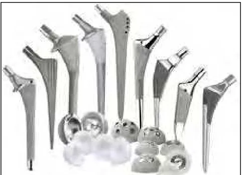
2.1 Typical Hip Joint Prosthesis 4
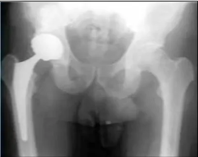
2.2 Hip Joint Prosthesis on Human Skeleton 7
2.3 Hip Joint Anatomy 10
2.4 Normal Hip Joint 11
2.5 Worn Out Hip Joint 11
2.6 Hip Joint Prosthesis 12
2.7 Comparison between Normal And Arthritic Hip 12
2.8 Acetabular Cup 13
2.9 Charnley Hip Stem 15
2.10 Comparison Between Straight And Curve Stem 17
2.11 Moore Type Were The Stem Is Straight 17
2.12 Charnley Type Were The Stem Is Curve 18
2.13 Worn Acetabular Cup 19
2.14 Metallic Tube Crush Test 37
2.15 Land mine detonating under a generic armoured vehicle resulting in loading from blast and soil throw
41
2.16 Finite Element Analysis On Hip Stem Using Ansys software
42
2.17 Peak stresses in an implanted hip prosthesis model 43
3.1 Shows the flow of the overall process which conducted from designing the hip joint prosthesis to analysis the stress and strain displacement using finite element analysis.
45
4.1 Hip Stem Design Parameter 54
4.2 Solid Model of Moore Femoral Stem 55
4.3 Construction of the Neck of Moore Hip Prosthesis 56 4.4 Construction of the Femoral Head of Moore Hip Prosthesis 57
x
4.6 Solid Model Of Charnley Femoral Stem 4.6
4.7 Sweep Paths for the Stem of Charnley Hip Prosthesis 59 4.8 Charnley Hip Prosthesis Stem after ‘dome’ 60 4.9 Solid Models of Charnley Hip Prosthesis 61 4.10 Sketch Model Of Acetabular Cup on Solidworks software 62
4.11 Revolve sketch of Acetabular Cup 62
4.12 Solid model of Acetabular Cup 63
4.13 Assemblies of Moore Prosthesis (Straight) 64 4.14 Assemblies Of Charnley Prosthesis (curve) 64
5.1 Editing Material Database 67
5.2 Choosing the Material Group for the Analysis 67 5.3 Material Selection for Changing the Mechanical Data 68
5.4 Editing Mechanical Data on Yellow Box 68
5.5 Choose the Analysis System to Use 69
5.6 Adding Custom Material to the Analysis 70
5.7 Importing Stem Design from Solidworks 71
5.8 Assign Material Were Used During Analysis 72
5.9 Entering a Value in the Element Size 73
5.10 Stem with 2.5mm Meshing Size 73
5.11 Force during Walking on Constant Speed 8km/hour Condition
75
5.12 Force during Stumbling Condition 75
5.13 Apply Force on the Analysis 76
5.14 Force properties 76
5.15 Amount and Direction of the Force 77
5.16 Apply Fixed Support on the Analysis 77
5.17 Fixed Support properties 78
5.18 Configure the Analysis Setting Properties 79 5.19 Specify the Stress Tools For the Solution 81 5.20 Result of Safety Factor Acquire From the Analysis 81
5.21 World Coordinate System 82
xi
5.23 Result of Total Deformation Acquire From the Analysis 82 5.24 Specify the Stress Von Mises for the Solution 84 5.25 Result of Equivalent Elastic Stress Acquire From the
Analysis
84
5.26 Specify the Strain Von Mises for the Solution 85
5.27 Result Generation Command 86
6.1 Maximum Load Resistance According Material on Straight Stem Design
88
6.2 Maximum Load Resistance According Material on Curve Stem Design
89
6.3 Safety Factor on Hip Stem With Force Range 1650 To 6500 N
90
6.4 Safety Factor on Hip Stem With Force Range 1650 To 6500 N
90
6.5 Safety factor on different hip stem design using PMMA material
91
6.6 Curve Stem Total Deformation Graph 92
6.7 Straight Stem Total Deformation Graph 92
6.8 Ligament around the Hip 93
6.9 Curve Stem Stress Displacement Graph 93
6.10 Curve Stem Stress Displacement Trend Line Graph 95 6.11 Straight Stem Stress Displacement Graph 95 6.12 Straight Stem Stress Displacement Trend Line Graph 97 6.13 Maximum Stress Concentration on Hip Stem Design 97 6.14 Comparison of Maximum Load Resistance According To
Stem Shape and Material
98
6.15 Comparison of Total Deformation on Stem Design 99 6.16 Comparison between Material were used on the Hip Stem
Design
xii
LIST OF TABLES
2.1 Chronology of hip prosthesis 8
2.2 Summary Mechanical Properties for Metal Use in Orthopaedic
Implant 23
2.3 Summary Mechanical Properties for Ceramic Use in Orthopaedic
Prosthesis 28
2.4 Summary Mechanical Properties for Polymer Use in Orthopaedic Prosthesis
33
4.1 Material Selection for the Analysis 65
5.1 Mechanical Properties Material Data Were Filled Into Data Base 69 5.2 Joint Force Bodyweight Multiplier on Human Activity 74
6.1 Maximum Load Resistance According Material on Straight Stem
Design 88
6.2 Maximum Load Resistance According Material on Curve Stem
Design 89
6.3 Result of Safety Factor on the Material Used On Curve Stem
Design 89
6.4 Result of Safety Factor on the Material Used On straight Stem
Design 90
6.5 Displacement of Stress of 6500 N on the Curve Stem Design with Different Type of Material
93
6.6 Displacement of stress of 6500 N on the Straight stem design with
different type of material 95
6.7 Displacement of stress of 6500 N on the Straight stem design with
different type of material 96
xiii
LIST OF ABBREVIATIONS
CAD - Computer Aided Design CAE - Computer-aided engineering
FEM - Finite element method FEA - Finite element analysis MPa - Mega Pascals(N/mm2)
mm - Millimetres
Cr - Chromium
Ni - Nickel
US - United States
NZ - New Zealand
1
CHAPTER 1
INTRODUCTION
1.1 Background
The human skeleton consists of rigid bones that are joint by joint which can rotates to enable movement. The hip joint is an outstanding example of a congruous joint. Both the acetabular and the femoral head are symmetrical, and the joint space is equal at all points with slight deviation to permit adequate lubrication. This symmetry allows for rotation about a fixed axis and simplifies the muscle action on that joint. The hip joint serves a very important biomechanical function. While supporting the majority of the human body with estimation 2/3 of total bodyweight and the joint must simultaneously facilitate smooth articulation of the lower limbs to enable bi-pedal gait. During routine daily activities, forces on the order of 5.5 times bodyweight are transferred between the femur and pelvis [Bergmann, 2001].If these joint unable to articulate courses by disease or injury, the human movement become difficult and become even impossible. The pain was produce from the movement from flexing the joints is known as arthritis disease.
2
300, 000 hips replaced every year worldwide, and the high costs involved, there is continuing strong demand for further improvement of orthopaedic devices, which lasted more than 20 years in the human body
Research in this area is going on since long time to develop new material and design, which will replace affected hip without incurring much pain to the patient and which withstand to maximum limitation of human activity. Recently many researchers working in this area applied finite element method to determine the failure of the artificial hip prosthesis.. The restoration of free and painless human movement by the implementation of artificial joint have become very important to patient were suffering for a very long time.
1.1 Problem Statement
Hip joint prosthesis is one of the most successful operations worldwide. However the number of reoperation and revision increase each year. Usually the reason for the revision is mechanical endurance of the material and design were lead to failure of the prosthesis. Prosthetic design and material selection greatly influence average survival rates of hip joint prosthesis. The wide selection of design and material for the prosthesis will produce various result of performance. The design of hip prosthesis and the material properties like mechanical strength is an important factor for the prosthesis. By understanding the design concept and mechanical properties on material selection, the optimum product of hip joint can be produce. The design and material toughness of the hip replacement is the criteria to make the prosthesis functioning last long.
1.2 Objectives
3
specific computational models have the potential to revolutionize the way that disorders of the hip joint are diagnosed and treated. However, first careful checked and validated the parameters that incorporate both computational and experimental techniques must be established.
The overall objectives of this project are:-
a) To design the hip joint prosthesis with two different shape using finite element analysis software.
b) To analyze the hip prosthesis on mechanical toughness on different material selection using finite element analysis software.
c) To optimise the design and material for the hip joint prosthesis.
1.3 Scopes of Project
The study concentrates on the design and analysis using finite element software of the hip joint prosthesis while implementing to the human body. The scope of study is briefly as follow:-
a) Structural design and material selection analysis using Ansys software
b) Structural analysis of the prosthesis excluding the hardware fabrication and physical mechanical test
1.4Gantt Charts
4
CHAPTER 2
LITERATURE REVIEW
2.1Introduction
In order to accomplish this project, the knowledge about the tools and procedure that will be used will be identified. This chapter explain in detail of the hip joint prosthesis, materials were used and reason to do the hip joint prosthesis.
The development of prosthetic hip joint is about a relation and integration between biomechanics and biomaterial. The knowledge of the joint biomechanics and the development of biomaterial are important for the hip joint prosthesis. The important element must be identified to perform structure alteration so the normal distribution of strength can been done to the artificial bone.
5
One of the most disturbing problems in hip joint prosthesis is the wear of acetabular cup. With an increase in number of articulations, a significant volume of material loss occurs (Pyburn & Goswami, 2004) by performed a finite element analysis to determine the stress distribution during the weight-bearing conditions for different stem shape. A stem design with broad lateral areas help transfer more loads during normal human activity and reducing the risk of hip prosthesis failure. Similar finite element studies (Pyburn E, Bennet & Goswami 2004) were performed to evaluate the importance of hip stem design for a successful total hip replacement. In a study reported by the author (Bhatt, 2008), several wear mechanisms were studied to examine the wear behaviour leading to prosthetic component loosening leading to hip dislocation. Four major contributing factors included in the study of wear rate were surface roughness, clearance between articulating surfaces of femoral head and acetabular cup liner, coefficient of friction, and sliding distance.
Although computational models have provided substantial additional insight to hip biomechanics above and beyond that obtained through experimental studies, substantial voids remain. In particular, simplifying model assumptions have often resulted predictions that are inconsistent with experimental measurements. Most models have not been validated by direct comparison with experimental data.
2.2 History
6
and Bohlinan on 1943, the first substitution of the femoral head on a large scale is owed to the Judet brothers (1946), who used a femoral head in polymethylmethacrylate (PMMA) linked to a stem that was inserted in the femoral neck as far as the lateral cortex. (Judet and Judet, 1950).
All these prosthesis were failures, either the cause by biomechanical or biomaterial. Subsequent to these failures, the prosthesis was made of chrome cobalt alloy. After other experience in substituting the femoral head using different kinds of materials by using material like Bakelite, ivory and stainless steel. The first end prosthesis with end medullar stem is owed to Austin Moore on 1943. His prosthesis, which was afterward widely used, was of chrome cobalt alloy, with a holed-in stem to allow bone growth and a collar to be placed on the femoral. A change in the prosthesis of Moore was made by Thompson on 1954.
The first total substitution of the hip joint prosthesis was due to McKee and Farrar, when in 1956 they began the era of prosthetic substitution of the hip. The prosthesis of McKee and Farrar on 1966 was of chrome cobalt alloy and constituted by a large head with diameter of 40 mm linked to a stem similar to Thompson’s, to be inserted in the medullar canal and articulated with a bone socket, also made of chrome cobalt alloy. Originally the prosthesis was fixed with screws, and then it was cemented with acrylic cement, thanks to the research of Charnley on 1970. The prosthesis of McKee and Farrar has been modified by Postel with the insertion, into the acetabular cup in order to reduce friction and favour lubrication.
7
of numerous failures due to rapid wear and consequent tissue reaction. After numerous attempts and research the best material was shown to be ultrahigh molecular weight polyethylene (UHMWPE). The cementation of the prosthetic component and the metal- polyethylene coupling allowed one to obtain a high rate of success. The result prosthesis with these characteristics were numerous, but all with heads of larger diameter. the prosthesis of Muller with a head diameter of 32 mm, the prosthesis of Bucholz with 38 mm, the trapezoidal prosthesis of Amstutz with 28 mm, and several others.
The aim of reducing bone resections to a minimum and preserving the bone patrimony brought up the idea of the resurfacing prosthesis (Muller, 1970), but the high rate of failures, both numerous and precocious, made them give up. On time passing by and the increasing spread of the prosthesization of the hip, it became evident that one of the more frequent problems of joint prostheses was the stability of the fixation of the prosthetic component to the bone.(Barbucci R.,2002)
Figure 2.2: Hip Joint Prosthesis on Human Skeleton (Orthodoctor.com)