DESIGN A LOAD BEARING CONVERTIBLE STRUCTURE FOR MOTORCYCLE
MOHD ZAKIRAN BIN ZULKIFLEE
ii
PENGAKUAN
“Saya akui laporan ini adalah hasil kerja saya sendiri kecuali ringkasan dan petikan yang tiap-tiap satunya saya jelaskan sumbernya”
DEDICATION
To my beloved mother, father, brother and sister, and all my friends All member of Bachelor of Mechanical Design Innovation Engineering (BMCA)
All lecturers from BMCA department Staff of Faculty Mechanical Engineering
Staff of Universiti Teknikal Malaysia Melaka (UTEM)
iii
ACKNOWLEDGEMENT
With the name of Allah, The Most Gracious and Most Merciful
iv
ABSTRACT
v
ABSTRAK
vi
2.4 Specification of motorcycle 17
3 METHODOLOGIES
3.1 Introduction 20
3.2 Research to find suitable motorcycle 20 3.3 Reference from load bearing previous research 20
3.4 Product Design 22
vii
3.6 Software have been used 24
4 RESULTS 30
DISCUSSION 42
5 CONCLUSION 43
REFERENCES 44
viii
LIST OF TABLE
TABLE TITLE PAGE
2.1 Functional process 15
2.2 Motorcycle specs 35
4.1 Material specification 31
ix
3.1 German Army motorcycle 22
3.2 German Army motorcycle 22
3.3 Motorcycle with plastic box 22
3.4 Motorcycle with aluminum box 22
x
3.26 Example CATIA 28
3.27 Example CATIA 28
3.28 Example CATIA 29
3.29 Example CATIA 29
3.30 Example CATIA 29
3.31 Example CATIA 29
4.1 boundary condition 32
4.2 deformed mesh 36
4.3 Von Misses stress 36
4.4 Diagram for vector 37
xi
LIST OF APPENDIX
APPENDIX TITLE PAGE
1 Sample of CATIA drawing 1 45
2 Sample of CATIA drawing 2 46
3 Sample of CATIA drawing 3 47
4 Sample of CATIA drawing 4 48
5 Sample of CATIA drawing 5 49
6 Sample of CATIA drawing 6 50
7 Sample of CATIA drawing 7 51
8 Sample of CATIA drawing 8 52
9 Sample of CATIA drawing 9 53
10 Sample of CATIA drawing 10 54
10 Sample of CATIA drawing 11 55
1
CHAPTER 1
1.1 Introduction
In this modern day, motor vehicle transport has become a necessity in human life. Transport vehicle has become the most convenient mechanism for ordinary people’s movement. There are several of transports in Malaysia namely bus, motorcycle, train, aeroplane and ship. Extensive used had caused the increased number of this freight transport. Besides that, the number of registered. However the number of accident also increased in proportion to the number of vehicle. Good vehicle design is a must nowadays and safety features are becoming the attractive point for costumer.
The objective of this work is design a product that could give more comfort and safety to the motorcycle passenger especially for the children. If the product is convertible, then this structure could be modified as a luggage carriage for the motorcycle rider. Proper goods placement or storage would help in one way or another thus pretending accident.
In planning design, this product will set up in the side body of a motorcycle. It will produce seating for two children. Besides that, this product also will become a luggage carriage.
2 1.2Objective
The objective of this project is to produce a product that will handle the mass or weight load that carriage by the rider. The criteria is to design a product attached to a motorcycle passenger that could station children of 3-5 years old. It is also importan that they are in comfortable and safe during a ride. Apart from that, the convertible structure is easy to modify and can be use for other purposes.
In this project, procedure of using tools like measuring tools, welding machine will be studied and practice in a correct way. Knowledge in software such as like CATIA and AUTOCAD will be improved. Theories like the Bending Moment theory, Cornering theory and Load test theory will be studied appropriately.
1.3Scope
In this project there are three scopes to be considered. The first and the most important is to design the product based on the engineering design theory.
The engineering theory like bending moment theory, cornering theory and load test theory will be look at in their respective view. The bending moment theory will be use to determined the maximum force that cause the bending in the structure member and chassis. The cornering theory is to find the stability for motorcycle during carrying this product. The load test is to determine the maximum load that can be support by the product.
The last scope is to gain more knowledge and practicing the skill in software like CATIA, NASTRAN and PATRAN. The CATIA is used to draw the product parts. These all parts will be joined together and this process calls the part
3 1.4 Problem statement
In Malaysia, motorcycle has become the most need mode of transport in the city and the small town. The motorcycle is cheap compared to other transport mode. However motorcycle has the disadvantage that might cause accident to the passenger and to the driver if not handle properly.
Usually the problem faced by motorcyclist is that not enough space for more than two passengers. As an example, several motorcyclists carried more than one passenger regardless of their safety and placed them inappropriately. This action might cause unnecessary stress the accident
In a traffic jam, people will try to be at the front line. Motorcycle with heavy load will cause many problems.
Sometime the luggage will distract their views and the road in front is blind. With heavy luggage,the rider might lost stability control and may cause the accident.
1.5 Project information
This product design based on the problem that faced by the
motorcyclist and the main idea is to design for child safety. In this design, extra carrier will be designed for two seats that suitable for children from 4 to 5 years old. This product is suppose to the ergonomic can be easily modified and suitable for load carriage as well. The product is designed to support load up to 500N.
The load carrier will be placed at side motorcycle body. This will give a good cornering and enough stability to avoid lost control. At the same time, the carrier can be supporter the motorcycle. By placing at the side the
motorcycle, the rider view will not be blocked. The rider knows the traffic situation. Additionally, by placing at side of the motorcycle, more space can be provided for the rider.
4 1.6 Report outline
Chapter 1, the information will presented. The project was study the load and the passenger (mostly children) more safety that related to the motorcycle design. The objective of study will be stated and the problem statement will be discussed. The scope and the benefit of the study will also be discussed in more details.
In chapter 2, the literature review is presented. The physical theories such as bending moment, cornering, and impact test will be discussed. These theories are very important, because in design a load bearing structure there is well to know the function of the parts such as bending in chassis.
Besides that, the previous design works and study will referred too. The information about the material used in the design will be define. The selected material should be light in weight, has a good stiffness and suitable to use as a load bearing for motorcycle. The data of a motorcycle that be collected. The Honda EX 5 motorcycle will be chosen as a reference. Sketches of the design structure will also show here.
In the methodology section, description of how the work project was conducted is being literate. It was shown in term of flow chart.
In chapter 4, the data and information obtained from analysis and simulation will be discussed. The result from Nastran and Patran, CATIA, and simulation using ADAM software will presented separately.
In chapter 5, the conclusion and recommendation for result and suggestion the further work were being listed.
5
Chapter 2
Literature review
2.1 Bending moment
In general, bending induces compression and tension axial stresses through resolution of the internal bending moments into a force couple as shown in the Figure 2.1. These axial stresses act normal to the beam cross-section. In ordinary wood beams, these axial stresses are acting parallel to the grain of the member. The distribution of axial stresses is linear with maximum stresses at the extreme fibers (outer edges of beam) and zero stress at the beam's neutral axis. For simply supported members with normal downward external loads, the beam experiences a positive internal bending moment condition; resulting in compression in the top fibers above the neutral axis and tension in the bottom fibers below the neutral axis. The more common loading condition is to stress the beam about its strong axis, (also known here as the x-axis), taking advantage of the larger moment of inertia that works to reduce bending stresses. This is the condition shown in the Figure2.1.
6 In beam design, one important criterion is to examine the beam's critical bending stress conditions. This is done by ensuring that the actual critical stress, developed as a function of loading, support conditions, span, and cross-section is ≤ the factored allowable stress. .
Since much of the bending problem, except for the adjustment factors, is a review from strength of materials, we will jump right into a bending example problem. For this and the following topics, the provided example problem is an analytical one, and not a design problem.
This is done to build your confidence with the basic stress techniques prior to the selecting and optimizing tasks that are done in design. The design aspects will be covered under the Design Example topic area of this Design module.
2.1.1 Bending criteria
Beams, joists, and rafters are ‘bending members’, and are perhaps the most common structural members. They are called ‘bending’ because their primary function is to resist bending forces. This is in contrast to say ‘tension’ members (cables, tie-rods, etc.) or ‘compression’ members (posts, studs, columns).
Bending members come in many shapes, sizes, and materials (wood, steel, and reinforced concrete are most common). Their primary function is to carry gravity loads over an opening or open area.
• Stresses in Bending Members.
There are two basic types of stresses in all bending members that must be considered in design.
• Shear Stress.
7 sag nearly as much. It is the glue and / or nails which keep the boards from sliding that is resisting the shear stresses. You can perform a similar experiment yourself by bending the pages of a book. If you don’t squeeze the pages together, thus allowing them to slide on top of each other, the book bends easily; very little shear resistance. But if you squeeze the pages so they can’t slide, now it is much harder to bend the book.
• Bending Stress.
A good way to think of bending stress is to imagine a long, heavily loaded experiencing large bending stresses at the sag. Try this experiment. Gently bend the tip of your index finger upward while keeping the knuckle stationary (i.e. bend it in the direction it won’t bend naturally). Notice the bottom of the finger, directly under the knuckle has stretched skin, i.e. skin that is in tension. The skin on top of the knuckle is wrinkled, i.e. it is in compression. There are bending stresses in your finger analogous to this tension and compression .Bending stresses are nothing more than tension on one side of a bending member simultaneous with compression on the other side. This simultaneous tension and compression is called a bending moment. The best ways to keep bending stresses low is to use deep beams, and / or short spans. For example, in the experiment above, if your finger were twice as tall (thick) as normal and you applied the same amount of force, the tension / compression would be considerably less. Also, if your finger was very short, and you applied the same amount of upward force as someone with a very long finger, you would feel much less tension / compression than the long-fingered person. Their ‘lever arm’ (also called moment arm) is longer, resulting in higher bending stresses.
2.1.2 The most common mistake in design load bearing carriage • Stress
8 2.1.3 Design for service life and service condition
The design requirements of product expected to be used only once or few times are very different than for product that have to perform for a very long time. A problem arise if a product designed for every short life or mild service condition is placed into much more severe service conditions or is expected to survive much longer the anticipated service life for which is it was designed. If the product fails under those strained circumstances, it is not fair to consider its demise a failure because it was exposed to service conditions far greater than expected. Nevertheless, courts have made judgments against manufacturers of products if such misuse is reasonably foreseeable.
2.2.1 Load test theory
Load Tests are end to end performance tests under anticipated production load. The objective such tests are to determine the response times for various time critical transactions and business processes and ensure that they are within documented expectations (or Service Level Agreements - SLAs). Load tests also measures the capability of an application to function correctly under load, by measuring transaction pass/fail/error rates. An important variation of the load test is the Network Sensitivity Test, which incorporates WAN segments into a load test as most applications are deployed beyond a single LAN.
Load Tests are major tests, requiring substantial input from the business, so that anticipated activity can be accurately simulated in a test environment. If the project has a pilot in production then logs from the pilot can be used to generate ‘usage profiles’ that can be used as part of the testing process, and can even be used to ‘drive’ large portions of the Load Test.
9 scale deployment, to ensure that new releases and changes in database size do not push response times beyond prescribed SLAs.
2.2.2 What is the load test?
Load testing is the process of creating demand on a system or device and measuring its response.
In mechanical systems it refers to the testing of a system to certify it under the appropriate regulations (LOLER in the UK - Lifting Operations and Lifting Equipment Regulations). Load testing is usually carried out to a load 1.5x the SWL (Safe Working Load) periodic recertification is required.
Load testing generally refers to the practice of modeling the expected usage of a software program by simulating multiple users accessing the program's services concurrently. As such, this testing is most relevant for multi-user systems, often one built using a client/server model, such as web servers. However, other types of software systems can be load-tested also. For example, a word processor or graphics editor can be forced to read an extremely large document; or a financial package can be forced to generate a report based on several years' worth of data. The most accurate load testing occurs with actual, rather than theoretical, results.
10 2.2.3 Why Conduct a Load Test?
A successful custom load test can ensure that the performance requirements of a complex software application, including the hardware landscape and the communication network infrastructure, have been met. Load tests are a best practice for large, highly customized, and mission-critical SAP system implementations.
2.2.4 What is the purpose of a Load Test?
The purpose of any load test should be clearly understood and documented. A load test usually fits into one of the following categories:
1. Quantification of risk. - Determine, through formal testing, the likelihood that system performance will meet the formal stated performance expectations of stakeholders, such as response time requirements under given levels of load. This is a traditional Quality Assurance (QA) type test. Note that load testing does not mitigate risk directly, but through identification and quantification of risk, presents tuning opportunities and an impetus for remediation that will mitigate risk.
2. Determination of minimum configuration. - Determine, through formal testing, the minimum configuration that will allow the system to meet the formal stated performance expectations of stakeholders - so that extraneous hardware, software and the associated cost of ownership can be minimized. This is a Business Technology Optimization (BTO) type test.
What functions or business processes should be tested?
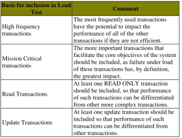
11 Table 2.1: Criteria for determining function process
Basis for inclusion in Load
Test Comment
High frequency transactions
The most frequently used transactions have the potential to impact the performance of all of the other transactions if they are not efficient. Mission Critical
transactions
The more important transactions that facilitate the core objectives of the system should be included, as failure under load of these transactions has, by definition, the greatest impact.
Read Transactions
At least one READ ONLY transaction should be included, so that performance of such transactions can be differentiated from other more complex transactions. Update Transactions
At least one update transaction should be included so that performance of such transactions can be differentiated from other transactions.
2.3 Cornering
12 The angle between the direction of the tyre and the tangent to the curve is known as the 'slip angle'. As the wheel is now no longer travelling exactly in the direction in which it is pointing, we can resolve its velocity tangent to the curve into components aligned with the wheel and at right angles to it. This means that the peripheral tyre speed will be slightly less than the road speed around the turn but there is now a sideways speed to the tyre, i.e. is it is sliding sideways. This lateral movement produces a force at right angles to the wheel direction. The magnitude of this force depends on the amount of slip angle, increasing up to about 15° and then falling off rapidly, that's when the driver has lost it. This wheel lateral force can now be resolved into a component at right angles to the direction of travel, cornering force, and into one aligned with the direction of travel, a drag force. It is this drag force which causes a car to slow when driven hard around a bend under constant power. So, we can now see what generates and controls the forces that cause a car to corner, and why the wheels must turn more than the amount just necessary to align with the direction of the curve.
2.3.1 The cornering force is provided from two sources:
1. Camber thrust and slip angle
As the inside edge of the tyre is forced to adopt a smaller radius than the outer edge, then for a given wheel rotational speed, the inner edge would prefer to travel at a smaller road speed, this happens if the wheel is allowed to turn about a vertical axis through the point of the cone. Just as a solid cone on a table if given a push. But if the bike was leaning over at 45° then for a normal size tyre the horizontal radius to the cone axis would be approximately 1.5 feet, an impossibly tight turn. However, attempting this turn will generate a centrifugal force which tends to throw the bike away from the centre of the turn and hence it will describe a larger radius. This then is the main mechanism for generating the cornering force on a bike, and is often referred to and misunderstood as "camber thrust".