UNIVERSITI TEKNIKAL MALAYSIA MELAKA
DESIGN AND DEVELOPMENT OF LINE
TRACKING ROBOT WITH OBSTACLE
AVOIDANCE
Thesis submitted in accordance with the partial requirements of the Universiti
Teknikal Malaysia Melaka for the
Bachelor of Manufacturing Engineering (Robotic and Automation)
By
MOHAMAD AIDIL B. ABDUL JALAL
Faculty of Manufacturing Engineering
UTeM Library (Pind.1/2007)
UNIVERSITI TEKNIKAL MALAYSIA MELAKA
BORANG PENGESAHAN STATUS LAPORAN PSM
JUDUL:
DESIGN AND DEVELOPMENT OF LINE TRACKING ROBOT WITH OBSTACLE
AVOIDANCE
SESI PENGAJIAN: Semest er 2 2007/ 2008
Saya Mohamad Aidil B. Abdul Jalal mengaku membenarkan laporan PSM / t esis (Sarj ana/ Dokt or Falsaf ah) ini disimpan di Perpust akaan Universit i Teknikal Malaysia Melaka (UTeM) dengan syarat -syarat kegunaan sepert i berikut :
1. Laporan PSM / t esis adalah hak milik Universit i Teknikal Malaysia Melaka dan penulis.
2. Perpust akaan Universit i Teknikal Malaysia Melaka dibenarkan membuat salinan unt uk t uj uan pengaj ian sahaj a dengan izin penulis.
3. Perpust akaan dibenarkan membuat salinan laporan PSM / t esis ini sebagai bahan pert ukaran ant ara inst it usi pengaj ian t inggi.
4. *Sila t andakan ( ) SULIT
TERHAD
TIDAK TERHAD
(Mengandungi maklumat yang berdar j ah keselamat an at au kepent ingan Malaysia yang t ermakt ub di dalam AKTA RAHSIA RASMI 1972)
(Mengandungi maklumat TERHAD yang t elah dit ent ukan oleh organisasi/ badan di mana penyelidikan di j alankan)
DECLARATION
I hereby, declare this thesis entitled “Design and Development of Line Tracking Robot with Obstacle Avoidance” is the result of my own research except as cited in the
references.
Signature :……….
Author’s Name : Mohamad Aidil bin Abdul Jalal
APPROVAL
This thesis submitted to the senate of UTeM and has been accepted as partial fulfillment of the requirements for the degree of Bachelor of Manufacturing Engineering (Robotic
And Automation). The members of the supervisory committee are as follow:
ABSTRACT
ABSTRAK
ACKNOWLEDGEMENTS
First of all I would like to thanks The Almighty God because with His permission let me finish this report with successfully. A lot of thank also for my beloved parents and all my family that always gave me a lot of support during this project.
I would like to express my sincere gratitude and appreciation to my supervisor, Pn. Syamimi bte. Shamsudin, who provide me a lot of ideas and guidance on how to success in this final year project. Without this guidance this project might not go as well as it is. The encouragement and motivation that was given during this project is under construction are greatly appreciated. I also would like to thank to the technician, En. Ashari, who have gave me technical supports and critics on my project.
TABLE OF CONTENTS
2. LITERATURE REVIEWS
2.1 Introduction to Robot 2.2 Robot Categories 2.2.1 Industrial Robot
2.2.1.1 Classification of Industrial Robots 2.2.2 Mobile Robot
2.2.2.1 Classification of Mobile Robots
2.2.2.2 Type of Mobile Robot Navigation 2.3 Major Component of Mobile Robot
2.3.1 Electric Motor 2.3.1.1 DC Motor
2.3.1.2 Brushless Dc Motor
2.3.1.3 Stepper Motor 2.3.1.4 Servo Motor 2.3.2 Sensor
2.3.2.1 Sonar Sensor 2.3.2.2 Infrared Sensor 2.3.2.3 Touch Sensor 2.3.3 Microcontroller
2.3.3.1 ROM 2.3.3.2 RAM 2.3.3.3 CPU
2.3.3.4 Input/Output Port 2.4 Programming 3.1.3 Implementation Phase 3.2 Project Planning
3.2.1 Identifying the Problem Statement, Objectives and Scope of Project
3.2.2 Literature Review
3.2.3 Methodology
3.3 Selection of Component 3.3.1 Brushless DC Motor 3.3.2 Microcontroller 3.3.3 Photoelectric Sensor
4. DESIGN AND DEVELOPEMENT
4.1 Electronic Circuit
5. TESTING, RESULT AND DISCUSSION
5.1 Introduction 5.2 Testing 5.3 Result 5.4 Discussion
6. CONCLUSION AND RECOMMENDATION
REFERENCE
APPENDICES
A: Using the MPLAB Integrated Development Environment (IDE) B: Programming ( Source Code)
94 98
LIST OF FIGURES
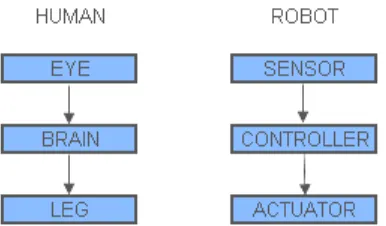
1.1 Block Diagram of Similarity Between Human and Robot
2.1 Assembly Line Robot
2.2 Cartesian Robot and it’s Work-Space 2.3 Cylindrical Robot and it’s Work-Space 2.4 Polar Robot and it’s Work-Space 2.5 Articulated Robot and it’s Work-Space 2.6 Mobile Robot
2.7 Legged robot
2.8 Autonomous Underwater Vehicle 2.9 DC Motor
2.10 Motor Construction and Terminology 2.11 Electric Motor Field-Current Interaction 2.12 Electric Motor Six-Winding Commutator 2.13 Electric Motor Theory Operation
2.14 Brushless DC Motor 2.15 Stepper Motor
2.16 Servo Motor 2.17 Sonar Transducer
2.18 Three Problems With Sonar Range Reading 2.19 Infrared Sensor
2.20 Touch Sensor
2.21 Elements on a Single Chip 2.22 Program Language Hierarchy
2.23 Top View of Sensor Layout in The SMART Car 2.24 Integrated System
2.26 GS-I type Mobile Robot
3.1 Project Planning
3.2 Base Conceptual Design 1 3.3 Base Conceptual Design 2 3.4 Base conceptual design 3 3.5 Example of Circuit Layout 3.6 Brushless DC Motor 3.7 PIC Microcontroller 3.8 Photoelectric Sensor
4.1 Circuit diagram
4.21 Attaching a Second Shaft to a Wheel
4.27 Attaching the Lifting Mechanism on Base Structure 4.28 Gripping Attachment
4.29 Integrating Circuit Boards on The Circuit Platform
4.30 Installing The Integrated Circuit Boards to Body Structure 4.31 Installing Limit Switch on The Front Side of Robot 4.32 Mobile Robot.
4.33 USB ICSP PIC Programmers 4.34 Line Tracking Module Code 4.35 Line Tracking Functions
4.36 Obstacle Avoidance Module Code
5.1 Straight Line 5.2 Starting Point
5.3 Detecting the Obstacle
5.4 Result after Turn Back at the Junction 5.5 Result after Senses an Obstacle
LIST OF TABLE
3.1 Specification of Photoelectric Sensor
4.1 Descriptions of board layout 4.2 PIC circuit board components 4.3 Descriptions of board layout 4.4 Descriptions of Board Layout
4.5 Motor Driver Circuit Board Components 4.6 Descriptions of Board Layout
4.7 Sensor Circuit Board Components 4.8 Descriptions of board layout
4.9 Power Supply Circuit Board Components
49
LIST OF ABBREVIATIONS
Erasable and Programmable Read Only Memory Central Processing Unit
CHAPTER 1
INTRODUCTION
1.1 Background
Robot is the one of technology that is growing rapidly in our modern world. We can see that, the utilization of robot today had being widely used in various fields. The robot can be used either to aid in human duty or replace the use of human to do a certain works. For example, robot has already widespread used in the industry especially in manufacturing sector where it used to replace the use of manpower in lifting heavy material or assembling part in production line. It may be caused by several factors such as may increase productivity, enhance quality and also can perform a dangerous task.
Figure 1.1: Block Diagram of Similarity between Human and Robot.
1.2 Problem Statement
Sensor is one of the important components in line tracking robots. It is because the skills of line tracking robots are highly dependant on the effectiveness of the sensor. Surrounding light could make the sensor produce a signal whereas it shouldn’t. This will cause the controller to make a wrong decision. As a result the robots will make unnecessary movement and can’t achieve it’s objective. The contrast between the background and the line can also cause a problem to the sensor. The sensor may detect the background as its line thus making a wrong decision.
cage motors or shorted field coils in synchronous motors. An uneven air gap, usually from badly worn sleeve bearings, also produces electrical unbalance.
1.3Project Objectives
The main aim of this project is to design an autonomous line tracking robot with the ability to avoid obstacle. This aim is achieved through these objectives:
1. To design and build the structure of an autonomous robot.
2. To construct suitable electronic circuits and integrate them with the robot structure.
3. To program the PIC to achieve line tracking and obstacle avoidance behavior.
1.4 Scope
1.5Project Overview
The goal of this project is to design an autonomous robot that can follow the defined path and detect obstacles. The concept of this robot is a wheeled robot that can move in two directions: forward and backward. The movement of the robot will be driven by two motors. As a path guideline, white line is created on the dark floor in order to make the contrast between of them should be large enough. In this project, the photoelectric sensors will be used to detect the white line and then convert into the electrical signal. There are four sensors will be used where three of them are placed close together at the front side of the robot and one sensor at the backside of the robot.
If the middle sensor at the front side and the sensor at the backside sense a presence of reflection, the robot will be properly positioned on the line. If the left or the right sensor sense a presence of reflection, the robot is not proper position on the line. In order to control these statements, the PIC controller is used to make a decision whether the motors should be move forward or backward depending on the instruction that have been programmed. Other feature of this robot is detecting the obstacle on the path. This feature is developed in order to avoid the robot from collusion with an obstacle and protect the motor from stalling.
CHAPTER 2
LITERATURE REVIEW
2.1 Introduction to Robot
Nowadays, majority of public have known what is robot. This is because, we can see that the robot already much used around our environment especially in industry, house, office and also military. However, the word of robot was introduced to several decades ago. The word robot is originated from the word Chez robota which means menial labor. We also found that there were many difference definitions if we refer to difference dictionaries. Therefore, the following definition from the Robot Institute of American can reflect main features of modern robot systems [1].
‘A Robot is a re- programmable multifunction manipulator designed to move materials, parts, tool, or specialized devices through variable programmed motions for
performance of a variety of tasks.’[1]
2.2 Robot Categories
When looking different kind and design robot which have been produced by various companies today, we could classify these robots into 2 main categories which are industrial robots and mobile robots.
2.2.1 Industrial Robot
Figure 2.1: Assembly Line Robot [9].
2.2.1.1 Classification of Industrial Robots
Industrial robots are only able to carry out their tasks in their work-space. Work-space means the maximum point of reach for the end-effector of an industrial robot. Usually, the work-space of industrial robots exists in 3 dimensional spaces. They also have a different work-space according to the 2 type of motion which are linear and rotate. The first 3 joint at the robot or called 3 major axes combination contribute the various shape of work-space and its can determine the position of wrist. Therefore, statements below will describe the 4 basic types of movement of industrial robot [3].
Cartesian Co-ordinate Robot: The first 3 major axes combination of this robot are linear.
work area on the y-axis. The Cartesian co-ordinate robot was developed mainly for arc welding, but it is also suited for many other assembly operations [1].
Figure 2.2: Cartesian Robot and it’s Work-Space [10]
Cylindrical Co-Ordinate Robot: The cylindrical co-ordinate robot is a variation of the
Cartesian robot. This robot consists of a base and a column, but the column is able to rotate. It also carries an extending arm that can move up and down on the column to provide more freedom of movement. The cylindrical co-ordinate robot is designed for handling machine tools and assembly [1].
Figure 2.3: Cylindrical Robot and it’s Work-Space [10].
Polar Co-Ordinate Robot: The polar co-ordinate robot or spherical co-ordinate robot
![Figure 2.1: Assembly Line Robot [9].](https://thumb-ap.123doks.com/thumbv2/123dok/655294.80014/23.612.195.467.96.304/figure-assembly-line-robot.webp)
![Figure 2.2: Cartesian Robot and it’s Work-Space [10]](https://thumb-ap.123doks.com/thumbv2/123dok/655294.80014/24.612.246.382.403.470/figure-cartesian-robot-s-work-space.webp)
