ISSN: 1693-6930
accredited by DGHE (DIKTI), Decree No: 51/Dikti/Kep/2010 267
Transient Stability Enhancement of the Power System
with Wind Generation
Sujith Mohandas, Ashwani Kumar Chandel* Electrical Engineering Department National Institute of Technology Hamirpur, India
e-mail: [email protected], [email protected]*
Abstrak
Analisis stabilitas transien sebuah sistem daya dengan pembangkit angin dibahas dalam makalah ini. Efek dari regulator tegangan otomatis, stabiliser sistem daya, kompensator sinkron statis pada sebuah system daya juga diteliti. Hasil berbagai simulasi menunjukkan bahwa penambahan stabiliser sistem daya dan kompensator sinkron statis mengurangi osilasi sudut rotor. Namun demikian, kompensator sinkron statis menunjukkan karakteristik pengurangan yang lebih baik dan meningkatkan stabilitas sistem terintegrasi angin. Kompensator sinkron statis telah memperkecil osilasi kecepatan secara mapan pada poros turbin angin kecepatan konstan. Sebuah indeks pengaruh transien telah diusulkan untuk membuktikan bahwa kompensator statis dapat memperkecil osilasi rotor.
Kata Kunci: kompensator, osilator, regulator tegangan, stabiliser, stabilitas transien
Abstract
Transient stability analysis of a power system with wind generation has been addressed in this paper. The effects of automatic voltage regulators, power system stabilizers, and static synchronous compensators on transient stability of a power system are investigated. Various simulation results show that addition of power system stabilizer and static synchronous compensators reduce the rotor angle oscillations. However, the static synchronous compensator shows better damping characteristics and improves the stability of the wind integrated system. It has been established that the static synchronous compensator damps out the speed oscillations in the shaft of the constant speed wind turbine. A transient impact index has been proposed to prove that the static compensator damps out the rotor oscillations.
Keywords: compensators, oscillations, stabilizer, transient stability, voltage regulator
1. Introduction
Out of the total generation of power, a large part of it is being met by the conventional power sources like thermal, hydro, and nuclear. However, due to some inherent disadvantages like increased environmental impact, decreased water availability and radiation hazards of the conventional power sources more emphasis is being given to tap the non-conventional resources like solar, tidal, geothermal and wind energy in the present time. However, the utilization of these resources which are usually dispersed in nature make the operation of the power system very complex. Therefore, studies like optimal power flow, unit commitment, steady state stability and transient stability of such a complex system need to be addressed and studied. The transient stability being very crucial for the operation of the system has to be studied for a wind interconnected power system. Transient stability entails the evaluation of a power system’s ability to withstand large disturbances and to survive the transition to another operating condition. These disturbances may be faults such as a short circuit on a transmission line, loss of a generator, loss of a load, gain of load or loss of a portion of transmission network [1].
Traditionally, power system transient stability issues have been evaluated by considering the rotor angle stability of synchronous generators [2-7]. The effects of wind generator on rotor angle stability and power oscillations have been attempted in [8-10].
introduce additional issues, e.g. voltage instability due to high reactive power consumption during transient disturbances [12]. Consequently, there is a need to carry out a detailed transient stability study which takes care of a system having wind generation. Hence, work in this direction is still wanting.
Present work the transient stability of a wind interconnected power system is examined by considering both rotor angle stability and voltage stability. The investigation analyzes the angular position of the rotor with respect to time after the fault occurs in the system with and without devices like automatic voltage regulator (AVR), power system stabilizers (PSS), and static synchronous compensators (STATCOM).
The paper is organized as follows. Problem formulation and the development of the solution methodology is described in section 2. Case studies and discussions with various scenarios like effect of wind generations, AVR, PSS and STATCOM are presented in section 3. Finally conclusions are drawn in section 4.
2. Research Method
In a transient stability study load flow calculation is performed to obtain system conditions before the disturbance. In addition, the machine currents prior to the disturbances are calculated from the following expression.
1, 2, 3...
where, m is the number of machines, Eci* is the conjugate of computed terminal voltage of the
ith machine,Ici is the current injected by the ith machine.
ci
P and
Q
ci are the scheduled or computed machine real and reactive terminal powers. When the machine i is represented by a voltage source of constant magnitude behindtransient reactance, the voltage is obtained from Ei'(0)=Eci+r Iai ti + jxdi' Ici, where
' ' '
(0) (0) (0)
Ei =ei + jvi is the initial value used in the solution of the differential equations. The initial internal voltage angle is expressed as
'
prior to the disturbance. This can be obtained from stator losses
ci
Pei =P + . When the effects of
saliency and changes in field flux linkages are taken into account a voltage behind the quadrature axis synchronous reactance is used to represent the machine [1-2]. The rotor dynamics of the alternator is given by
( ) for 1, 2...,
whose parameters vary with slip. The induction generator equations are summarized as
Equations (3) and (4) are simplified for implementation in transient stability studies. The rotor currents are eliminated to derive the relationship between stator current and voltage in terms of a voltage behind the transient reactance. The stator voltages can be combined and expressed in phasor form as:
~
where
x
s'is the transient reactance of the induction generator.Eliminating the rotor currents and expressing the rotor flux linkages, equation (4) can be written as:
speed in radians per second.
L
sandL
r are p.u stator and rotor leakage inductances.'
The rotor acceleration equation is given as
T
is the p.u electromagnetic torque developed by induction generator withω
s=1.0 p.u.' '
Te =v id ds+v iq qs (8)
order Runge-Kutta method is used to solve the differential equations. In the stability study for the considered test system, three different states as given below are considered:
1) The prefault state which determines the initial condition for angles X i( ) where
i
= 1, 2, …, n (n is the number of synchronous machine in the system).2) The fault state exists at t=t0 and persists until the fault is cleared at t=tcr
3) The post fault state with t>tcr(t is fault clearing time and tcr is the critical clearing time). In the stability analysis for the considered system, the assumptions as taken in [13] are considered. The algorithm for the solution of swing equation is as follows.
Step1. Model the network.
Step2. Perform load flow analysis and compute the bus voltages and power injections. Step3. Compute the initial machine internal voltages.
Step4. Compute the prefault admittance matrix Ybus, prefault.
Step5. Solve the swing equation for the prefault period. Step6. Set t=0 and fault bus voltage equal to zero.
Step7. Compute the fault system admittance matrix Ybus, fault.
Step8. Solve the swing equation for the fault period. Step9. Isolate the faulted line.
Step10. Compute the post fault admittance matrix Ybus,post fault.
Step11. Solve the swing equation for the post fault period. Step12. Plot the rotor angle, power and voltage variations.
The simulations have been done in power system analysis toolbox (PSAT) and MATLAB/SIMULINK® [14-15].
3. Results and Analysis
The transient stability of the different configurations of the power system is considered and the results thereon obtained are presented in this section.
3.1. Case 1
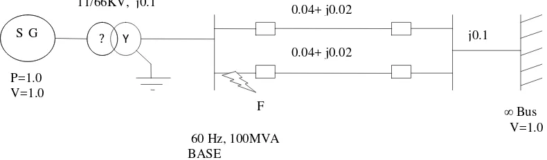
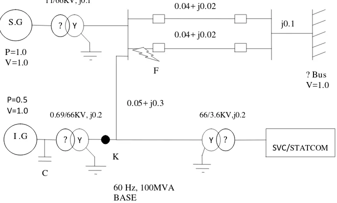
Power system shown in Figure 1 a synchronous generator (SG) is connected to an infinite grid through a transformer and a double circuit.
Figure 1. Basic power system for transient stability.
The double circuit transmission line parameters are R and X respectively. The system is similar to the one as given in [1]. The system data has been taken as given in [1]. The fault considered is a symmetrical three phase to ground fault which occur at point F. The fault occurs at t = 1.0 secs in line 2 shown in Figure 2 and the circuit breakers on the faulted lines are opened at t = 1.01 secs. At t = 1.07 secs the fault is cleared and the circuit breakers are reclosed.
It is mentioned that three different conditions as mentioned below have been analyzed and the transient stability under these conditions is determined:
1) The generator is not equipped with any excitation controllers like AVR and PSS. 2) The generator is equipped with AVR.
3) The generator is equipped with both AVR&PSS.
F
0.04+ j0.02
0.04+ j0.02
S G ? Y
11/66KV, j0.1
P=1.0 V=1.0
j0.1
∞ Bus
V=1.0 60 Hz, 100MVA
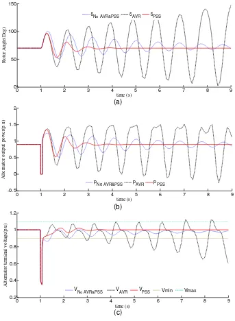
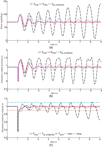
The results for the above mentioned conditions under various network conditions namely pre-fault, during fault and the post- fault are analyzed and shown in Figure 2. Rotor angle vs. time plots for pre-fault (both circuits in service) i.e. upto time t = 1.0 sec. during fault which occurs at point F in line 2 and the post fault (circuit 2 is out of service) for various excitation conditions are shown in Figure 2(a). During fault no power is transmitted to infinite bus. The short circuit current flows through pure reactance to the fault. Hence, only reactive power flows and the active power at the air gap is zero during the fault. The maximum power transfer occur at δ=900, beyond this value the system goes into instability. The plot clearly shows that when the effect of excitation controllers like AVR and PSS are not included, there exists a continual oscillation of rotor angle about δ=900 and is shown by a dotted line in Figure 2. Hence, there exists oscillation instability.
(a)
(b)
(c)
Figure 2. (a).The Rotor angle curve showing the effects of AVR and PSS. (b). Output power delivered by alternator. (c). Alternator terminal voltage showing the effects of AVR and PSS.
With AVR alone the system goes into complete unstable region. However, the PSS has been able to damp out the rotor angle oscillation once the fault is cleared and hence with PSS
0 1 2 3 4 5 6 7 8 9
No AVR&PSS pAVR pPSS
0 1 2 3 4 5 6 7 8 9
the system is in stable condition. This condition has been shown by a solid line in Figure 2(a). If the rotor angle oscillations are left undamped, it will cause rapid power oscillations even after clearing the fault this is shown in Figure 2(b). The power oscillations cause undesirable tripping of the protective relays. When an AVR is present as an excitation controller for the generator then the rotor angle oscillations persist and are enlarged in magnitude as the is elapsed causing rotor angle instability. The generator terminal voltage Et is compared with reference and the error is fed into a high exciter gain, without any transient gain reduction or derivative feedback. The terminal transducer is assumed to have a time constant
T
R. The presence of dips in power waveform is due to the effect of time constant of the terminal transducer.Power system stabilizer (PSS) and AVR as an excitation controller for the generator there exists a damping effect. The generator rotor angle oscillations under such a system are reduced and are shown in Figure 2(a). However the system remains stable without the loss of synchronism. The damping is provided by producing a component of electrical torque in phase with the rotor speed deviations. The settling time of the oscillations is 3.5 to 4 secs. Hence, due to an early settling of the oscillations the undesirable relay tripping is avoided in this case.
The plots in Figure 2(c) show the terminal voltage variation of the alternator with time. Without any controller the terminal voltage is not constant and is of varying in nature. With AVR alone the generator terminal voltage has large variations because of rotor angle instability. As the PSS damps out the oscillations in the voltage waveform AVR and PSS enhances the voltage stability. The terminal voltage in this case lies well within the stability limits as shown with solid line.
3.2. Case 2
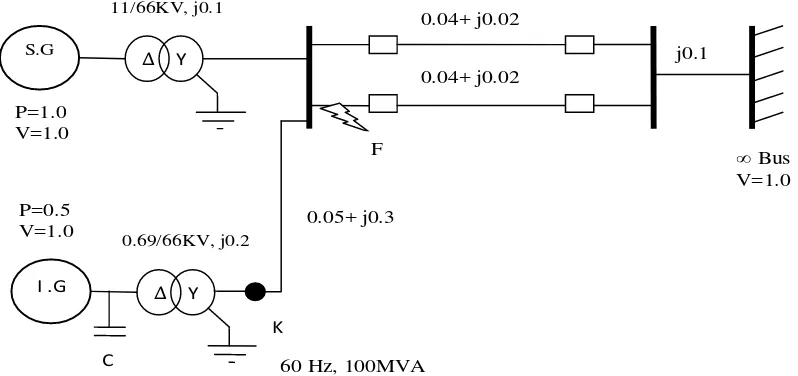
The power system in case 1 is modified by including a wind generator as shown in Figure 3.
Figure 3. The modified system with wind generation.
The data in p.u at a base of 2220 MVA for the wind generator is as given below. Induction generator data: rating 50 MVA, 0.69 kV, Rs= 0.01, X s= 0.1, Rr= 0.01, X r=0.1, X m
= 3.5, H= 0.5, turbine Data: H wr= 2.5 and gear ratio: 1/89; where, Rsis the stator resistance,
X sis the stator reactance, Rris the rotor resistance, X ris the rotor reactance, X mis the mutual reactance, His the inertia constant of the rotor andH wris the inertia of the turbine rotor.
0.04+ j0.02
0.04+ j0.02
F
j0.1
∞ Bus
V=1.0
S.G
Δ Y
11/66KV, j0.1
P=1.0 V=1.0 3
I .G
Δ Y
P=0.5 V=1.0
C
0.69/66KV, j0.2
K
0.05+ j0.3
The system comprises a constant speed wind turbine (CSWT) coupled to terminal bus of the alternator (Bus 1), through a transformer. A capacitor is placed at the terminals of the CSWT for providing the necessary reactive power compensation.
(a)
(b)
(c)
(d)
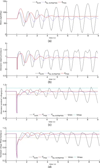
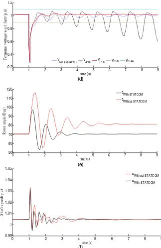
Figure 4. (a) Rotor angle curve, (b) output power delivered by alternator, (c) alternator terminal voltage, and (d) terminal voltage of wind farm, with wind generation showing the effects of AVR
and PSS.
AVR pNo AVR&PSS pPSS
0 1 2 3 4 5 6 7 8 9
AVR VPSS VNo AVR&PSS Vmin Vmax
0 1 2 3 4 5 6 7 8 9
Three phase symmetrical fault is considered to occur at t=1.0secs. The circuit breakers angle oscillates around a value less than 900 causing oscillating instability.
The PSS along with AVR damps out the rotor angle oscillations. However, the settling time for the oscillations in rotor angle and in output power is more when the wind generation is included, and is around 6.5 to 7secs as is obtained from Figure 4(b). The transient stability not only has to consider the rotor angle stability of the alternator but also the voltage stability as the induction generators associated with the CSWT consumes high reactive power and can lead to voltage instability. The terminal voltages of both alternator and wind farm show oscillations around a value less than 1 p.u with out any excitation controllers. PSS with AVR damps out the oscillations in the voltage waveforms and the voltage levels lie at 1 p.u which is well within the limits after the fault has been cleared as is evident from Figure 4(c) and Figure 4(d) respectively. The delay in damping out the oscillations can lead to frequent and undesirable tripping of protective relays even after the fault has been cleared.
3.3. Case 3
Effect of STATCOM on the system of case 2 on the rotor angle and voltage stability has been analyzed. The STATCOM is connected to the terminal bus (Bus 1) through a coupling transformer as shown in Figure 5. The data for the STATCOM is as follows. Rating: 50 MVA, 3.6 kV, current control parameters gainKr =50, time constantTr =0.1sec.
Figure 5. The Modified system with wind generation and STATCOM.
The STATCOM exchange the reactive power with the system bus is connected and directly affects the stability of the system. Three phase symmetrical fault is considered to occur at t = 1.0 secs. The circuit breakers on the faulted lines are opened at t = 1.01 secs and at t = 1.07 secs the circuit breakers are reclosed after the fault has been cleared. The case is also analyzed for the three different conditions mentioned in case 1 and 2 respectively. The results thus obtained are as shown in Figure 6.
better damping. The system is unstable even with the addition of the STATCOM when no excitation controllers are provided in the power system. This is seen from the dotted plot in Figure 6(a). It can be inferred from Figure 6(a) that inclusion of AVR and PSS the oscillations in rotor angle are reduced. Figure 6(e) found that due to the placement of STATCOM the settling time of oscillations is reduced to around 3 seconds, hence the stability is enhanced with the installation of STATCOM in the power system. The power output also shows the similar characteristics as the rotor angle. It can be inferred from Figure 6(b) that there is a reduction in the power oscillations and the settling time has also reduced significantly in presence of STATCOM. Hence the rapid power swings in the line is reduced. Consequently, the frequent tripping of protective relays and undesirable interruptions can be avoided.
(a)
(b)
(c)
Figure 6. The results of the STATCOM exchange the reactive power with the system bus (a) Rotor angle curve, (b) output power delivered by the alternator, (c) Alternator terminal
voltage with STATCOM showing effects of AVR&PSS.
0 1 2 3 4 5 6 7 8 9
AVR pPSS pNo AVR&PSS
0 1 2 3 4 5 6 7 8 9
(d)
(e)
(f)
Figure 6. The results of the STATCOM exchange the reactive power with the system bus; (d) Terminal voltage of wind farm with wind generation and STATCOM showing the effects of AVR
and PSS (e) relative rotor angle curves, and (f) Relative shaft speed curves with and without STATCOM (continued)
The terminal voltage variation of alternator and the wind generator for this test case for the three different operating conditions of the power system are shown in Figure 6(c) and 6(d) respectively. It can be clearly seen that the voltage stability has increased in the presence of a STATCOM due to an early damping of oscillations in voltage waveform. Another major improvement while placing STATCOM is the damping of speed oscillations in the shaft of the wind turbine shown in Figure 6(f). The main reason for this improvement is due to the immediate settlement of the power oscillations. If the speed oscillations are not damped out it causes damage to the rotor shaft and gear box of the CSWT. Hence placement of a STATCOM permits
0 1 2 3 4 5 6 7 8 9
No AVR&PSS VAVR VPSS Vmin Vmax
the wind farm to be operated safely even during a network disturbance such as a symmetrical three phase faults.
3.4. Transient stability impact index
The impact of addition of components like AVR, PSS, STATCOM, wind farm etc. on the transient stability of the system is also computed. Transient stability impact (TSI) factor is proposed and is as given in equation (9).
360 max leads to a low power transfer and instability. δ below this limit leads to lesser power transfer but the system is stable. For δmax = 90, the TSI is 0.6, i.e. the ideal value for a stable system
transferring maximum power is 0.6. But with more components being added to the system such as wind generation TSI deviates from the ideal value. The deviation from the ideal value can be represented as a percentage impact factor given by equation (10).
0.6
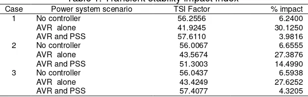
The impact factor of various scenarios is given in Table 1. The impact percentages close to zero is very stable. As the value increases, the stability goes on decreasing. TSI factor shows the impact of the particular scenario on the system. The ideal value of TSI is 60, as the value for a particular scenario deviates from ideal the impact on the system is also high depending on the deviation. Case 1 with only AVR shows a high value of impact than without any excitation controllers. Inclusion of AVR along with PSS shows the least impact. Similarly for case 2, inclusion of AVR alone cause severe impact than without any controllers but addition of AVR along with PSS reduces the impact on the system. STATCOM is installed in the wind integrated system the impact is considerably reduced with the addition of AVR along with PSS.
Table 1. Transient stability impact index
References
[1] Kundur P. Power System Stability and Control. New York: McGraw-Hill. 1993: 699–869. [2] Stevenson WD. Elements of Power System Analysis. New York: McGraw-Hill. 1982: 402.
[3] Yorino N, Priyadi A, Kakui H, Takeshita M. A New Method for Obtaining Critical Clearing Time for Transient Stability. IEEE Transactions on Power Systems. 2010; 25(3): 1620-1626.
[4] Xue Y, Cutsem Th V, Pavella MR. Extended Equal Area Criterion Justifications, Generalizations, Applications. IEEE Transactions on Power Systems. 1989; 4(1): 44-52.
[5] Debs A. Voltage dip at Maximum Angular Swing in the Context of Direct Transient Stability Analysis.
IEEE Transactions on Power Systems. 1990; 5(4): 147-1502.
[6] Nimje AA, Panigrahi CK. Transient Stability Analysis Using Modified Euler’s Iterative Technique. IEEE Conference on Power Systems. Kharagpur. 2009: 1-4.
[7] Hakimmashhadi H, Heydt GT. Fast Transient Security Assessment. IEEE Transactions on PAS. 1983; 12(1): 3816 –3824.
[8] Muljadi E, Butterfield CP, Parsons B. Effect of Variable-speed Wind Turbine Generator on Stability of Weak Grid. IEEE Transactions on Power Systems. 2007; 22(1): 29-36.
[9] Rosas P. Dynamic Influences of Wind Power on the Power Systems. PhD Thesis. Denmark: Technical University of Denmark; 2003.
[10] Rasmussen J, Jorgensen P, Palsson MT, Uhlen K. Wind Power Impact on Transient and Voltage Stability of the Power System in Eastern Denmark. 8th IAESTD International Conference on Power and Energy Systems. Marina del Ray. 2005: 143-150.
[11] Ackermann T. Wind Power in Power Systems. New York: McGraw-Hill. 2005: 15–64.
[12] Canizares CA, Pozzi M, Corsi S, Uzunovic E. STATCOM Modeling for Voltage and Angle Stability Studies. International Journal on Electrical Power and Energy Systems. 2003; 25(6): 431-441. [13] Iyambo PK, Tzoneva R. Transient Stability Analysis of the IEEE 14- Bus Electric Power System.