Published in IET Control Theory &Applications Received on 6th December 2013
Revised on 21st August 2014 Accepted on 17th September 2014 doi: 10.1049/iet-cta.2014.0544
ISSN 1751-8644
Practical and robust control for precision motion:
AR-CM NCTF control of a linear motion mechanism
with friction characteristics
Shin Horng Chong
1,2, Kaiji Sato
21Faculty of Electrical Engineering, Universiti Teknikal Malaysia Melaka, 76100 Malacca, Malaysia
2Interdisciplinary Graduate School of Science and Engineering, Tokyo Institute of Technology, 4259 Nagatsuta, Midori-ku, Yokohama 226-8502, Japan
E-mail: [email protected]
Abstract:This study presents the framework of the acceleration reference continuous motion nominal characteristic trajectory following (AR-CM NCTF) control system, and its effectiveness in a linear motion mechanism with friction characteristics is experimentally demonstrated in comparison with the other control methods. The overall control system comprises the feedback-loops for velocity reference and acceleration reference following controls. The AR-CM NCTF control is an enhanced continuous motion NCTF (CM NCTF) control that has been proposed for high-precision motion. It has the same structure as the CM NCTF controller with additional elements for high-precision motion. The design procedure of the AR-CM NCTF controller remains easy and is independent of friction characteristics. The usefulness and advantages of the proposed controller are shown in the experimental studies. Besides, this study also highlights the robustness of the AR-CM NCTF controller by examining its performances in point-to-point and tracking motions in the presence of mass and disturbance force variations. In the robust performance, the AR-CM NCTF controller is compared with two types of proportional derivative control systems with disturbance observers (PDDOs). The comparative experimental results illustrate that the AR-CM NCTF controller shows the higher motion performances the higher robustness to plant parameter variations than the PDDO controllers.
Nomenclature
M mass of the table
Kf force constant
cn damping coefficient
Ff coulomb friction force
x(t) table displacement
xr reference input
Gn NCT’s blocks
Gc PI compensator
Gp linear motion mechanism with friction
characteristic
Kfm equivalent gain represents the force constant is
divided by the mass of the table
α equivalent gain represents the damping coefficient is divided by the mass of the table
Ffmax maximum friction force
Td time constant of derivative elements with filter
T sampling time
N number of sample data
e positioning and tracking error
˙
e error rate
¨
e rate ofe˙ ˙
eNCT error rate of NCT
¨
eδ rate of error rate of theδ-element
erms root mean square of tracking error
β inclination of NCT near origin
δ inclination near origin of δ-element
λ adjustable gain of λ-element
up1 difference between the error rate e˙ of the
mechanism and the error rate of the NCT
up2 λ multiply the difference between the e¨δ and
the e¨
up summation signals ofup1 andup2
Kp proportional gain
Ki integral gain
ζ damping ratio
ωn natural frequency
1
Introduction
improvement is onerous and costly. For this account, a practical controller of which design procedure and struc-ture are simple and transparency, and which is capable to produce fast response, nearly zeros overshoot, high robust performance and excellent accuracy is required as a solution especially in industry.
In practical application, classical controllers such as the PID and lead–lag controllers still are the most commonly applied controllers for their well-understood, simplicity, reliability, easy to implement. They offer fairly good per-formance in many applications. Their dominance is evident even today across various sectors of the entire industry [2– 4]. However, the classical controllers have met limitations with the recent demanding requirements. Many advanced controllers have been devoted to achieve the high position-ing and robustness performance, such as robust controllers with disturbance observer [5–8], a combination of friction compensator, a disturbance observer, a position feedback compensator and a zero-phase error tracking controller as a feed-forward compensator [9], adaptive robust controllers [10–13], state-feedback controller [14], sliding mode con-trollers [15–18] and advanced intelligent concon-trollers. Yet, such controllers are not easy to design as conventional PID controllers, and always require known model parameters of the plant. The control performance depends on the accuracy of the dynamic model and its model parameters that are used in the design procedure. Besides, the sufficient knowl-edge of control methods in their design procedures is strictly needed. These needs present barriers to their practical use. For this reason, the classical controllers are still widely used in industrial application because of their simple structure and ease of design.
A nominal characteristic trajectory following (NCTF) controller has been proposed as a practical controller which emphasises a simple and straightforward design procedure in order to achieve the promising results in positioning and continuous motion (CM) control. The basic NCTF controller has been examined for point-to-point positioning as well as CM NCTF controller for CM such as tracking and con-touring motions [19–23]. Up to date, the NCTF controllers have been improved steadily to enhance its performance in positioning, tracking and CM control. They also have been proved to have the design procedure that is indepen-dent of friction characteristic [21]. The design procedure of the NCTF controller is no longer influenced by the non-linear characteristics of mechanism, such as saturation and friction characteristics. In recent research about NCTF con-trol, an improved CM NCTF concon-trol, namely acceleration reference CM (AR-CM) NCTF control has been proposed and investigated. The birth of AR-CM NCTF control is for the improvement of overshoots reduction characteristics and low sensitivity to disturbance force [22]. It provides high disturbance rejection characteristics to achieve improvement in positioning and tracking accuracies. In [22], the AR-CM NCTF control has been applied to a frictionless mechanism in order to examine its basic characteristic and usefulness. On the other hand, many precision positioning mechanisms have friction characteristics and it is important to clarify the usefulness of the AR-CM NCTF control on the follow-up performance and the robustness. This paper focuses on the clarification.
In [23], the AR-CM NCTF controller was implemented to a ball screw mechanism, which is a typical positioning mechanism with friction characteristics. The usefulness of the controller has been only evaluated in point-to-point posi-tioning and tracking motions, without any validations of the
robustness of the controller. Therefore, in this paper, the robustness of the AR-CM NCTF controller is validated with the presence of mass and disturbance force variations. For that, the proportional derivative controllers with disturbance observer (PDDO controllers) are designed and compared in the presence of mass variations and friction force changes in addition to the CM NCTF controller. The PDDO controller is a typical robust controller for motor driven mechanisms. Many researchers have examined the effectiveness of the PDDO control [24–28]. It is relatively easier to design than the other advanced controllers and often shows higher robust to the disturbance force and model parameter changes. Thus, in recent years, the disturbance observer has become one of the most commonly used schemes in industrial applications although it takes more knowledge of control theory to design it than the PID controller.
The remainder of this paper is organised as follows. In Section 2, the experimental setup including the linear motion mechanism with friction characteristics is described. Section 3 explains the concept and structure, the practical design procedure, the stability and characteristics analyses of the AR-CM NCTF controller. In Section 4, motion con-trol performances of the AR-CM NCTF concon-trol system, such as positioning and tracking control performances, and its robustness, are evaluated and compared with those of the CM NCTF and PDDO control systems. Finally, in Section 5, the conclusions are drawn.
2
Experimental apparatus
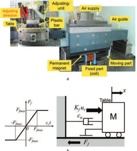
The linear motion mechanism with friction characteristics depicted in Fig.1ais used to evaluate the usefulness of the AR-CM NCTF control system. The mechanism consists of an air-guide (manufactured by NSK) and a voice-coil motor
a
b
Fig. 1 Experimental setup and dynamic model of the linear motion mechanism
a Experimental linear motion mechanism
(VCM). The mechanism has a working range of±22 mm. To measure the displacement of mechanism, a laser position sensor (AGILENT TECHNOLOGIES 10897B) with a reso-lution of 1.24 nm is used. An amplifier, of which the output voltage and current are limited within a range of at ±40 V and±6 A, is employed to drive the VCM. The controller is implemented at a sampling rate of 2.5 kHz.
Although the mechanism is fundamentally under non-contact condition, the adjusting unit can add friction charac-teristics to the mechanism. The contact condition between the plastic bar and the table is adjustable. The grease is located between them. Fig.1billustrates the dynamic model of the mechanism with friction characteristics and its param-eter values are shown in Table1. The linearised open-loop transfer function of the dynamic model is expressed as
Gp(s)=
3
AR-CM NCTF control framework
3.1 Concept and structure
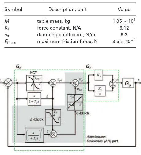
The structure of the AR-CM NCTF control system is shown in Fig.2. It includes the CM NCTF controller structure and has an extended-part, which is named as the AR part (see shaded-part in Fig.2). The CM NCTF controller comprises a nominal characteristic trajectory (NCT) and proportional– integral (PI) compensator [21].
The AR part works efficiently to improve the follow-ing characteristic of the object motion on NCT that is helpful in motion accuracy enhancement. The AR part consists of additional controller elements:δ-element andλ -element. The δ-element represents the virtual acceleration reference, which is constructed from the open-loop acceler-ation response with the inclinacceler-ation same as the NCT near
Table 1 Model parameters
Symbol Description, unit Value
M table mass, kg 1.05×101
Kf force constant, N/A 6.12
cn damping coefficient, N/m 9.3
Ffmax maximum friction force, N 3.5×10⁻¹
Fig. 2 Block diagram of AR-CM NCTF control system
the origin on a phase plane. The λ-element is a parameter to be adjusted to work well with theδ-element and improve the motion accuracy.
The key issue that affects accuracy and causes the over-shoot is because of the insufficient motion characteristic of the control system to reach and follow the NCT and stop at the origin on the phase plane. Therefore it is of paramount importance to improve the following accuracy of the move-ment to the NCT. The improvemove-ment could lead to high overshoot reduction characteristics and high positioning and motion accuracies. In an effort to further improve them, the AR part is added. The AR part includes theδ-element as the suitable deceleration trajectory for the mechanism motion to follow the NCT. Although the λ-element is adjusted adap-tively to work well with the δ-element in order to improve the motion accuracy. Overall, the AR part helps to reduce the difference between the actual error rate and the reference error rate(e˙− ˙eNCT), especially near the origin.
3.2 Design procedure
The design procedure of the AR-CM NCTF control sys-tem in [22] is including the design procedure of the CM NCTF controller [21]. It remains easy and practical with the following design procedure:
(I) NCT construction and PI compensator determination:
The same constructed-NCT and PI compensator for the lin-ear mechanism with friction as the previous CM NCTF in [21] is used.
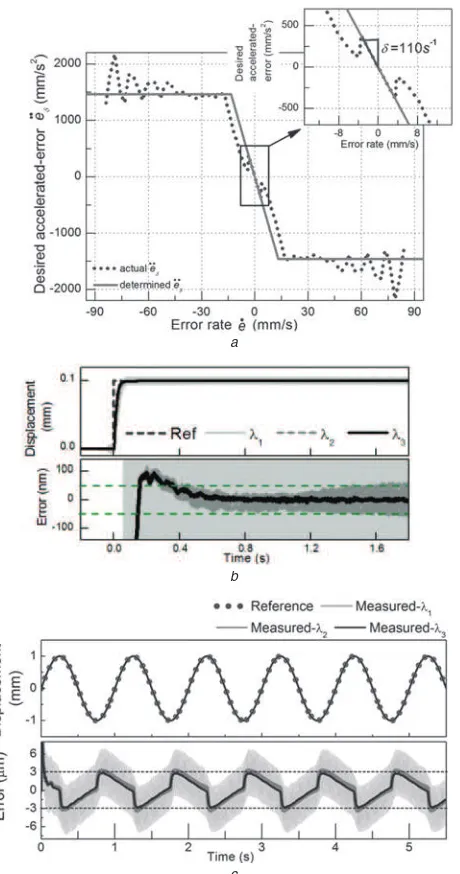
(II) δ-block construction:Theδ-block of which, the inclina-tion near origin is the same as NCT,β is constructed. There is no extra experiment requested. From the NCT, the e¨δ is
determined as
Fig. 3a shows the constructed δ-block for the mechanism with friction. The solid line represents the trajectory of e¨δ
from the actual one (dotted-line). For simplicity, theδ-block is approximated by the polygonal line.
(III) Time constant determination of derivative elements with filter: The derivative element with the filter is adopted to reduce the bad influence of the derivative action, result-ing from the quantisresult-ing errors and electrical noise. The time constant (Td) of the filter can be simply determined from
the inclinations of the NCT in the neighbourhood of the origin, β. In this paper, the selected Td is twice larger the
value ofβ. The selected time constant is useful to filter suit-ably the noise and to avoid the significant influence to the dominant dynamic characteristics of the control system. (IV) λ-block construction:The parameterλis an adjustable gain. It is determined in order to reduce the (e˙− ˙eNCT) as
shown in Fig. 2. The gainλis adjusted to reduce the resid-ual vibration in the positioning. This paper adoptsnλβ=1; where n is integer 1, 2, 3,. . .. The following part will explain explicitly the influence of λ and its selection for the linear mechanism with friction.
The positioning experiments of the AR-CM NCTF con-trol system have been conducted with three different λs:
λ1 (1/β), λ2 (1/2β) and λ3 (1/3β) to 0.1 mm step inputs,
as shown in Fig. 3b. The step responses and the position-ing accuracies are illustrated. The result with λ3 shows a
a
b
c
Fig. 3 Determinedδ-block and experimental step and sinusoidal responses forλselection
a Determinedδ-block as acceleration reference
b Step responses to 0.1 mm
c Tracking responses to sinusoidal input: amplitude: 1 mm, frequency 1 Hz
motion error as compared with the results ofλ1 (>100 nm)
andλ2(≃50 nm). For tracking motion, the performances of
threeλs were examined with the sinusoidal reference input of 1 mm amplitude and 1 Hz frequency (see Fig.3c). Obvi-ously, the performance of the λ3 (the smallest value of
lambda) results in the smallest error amplitude, which is about half of theλ1one. These results indicate that the
opti-malλcan be determined from the smallest residual vibration for positioning and tracking motions. On the basis of the positioning and tracking results, therefore theλ3 is selected
for the rest of the experiments in this paper.
The characteristic near the reference position (origin) is important for positioning and influences the motion accu-racy. The reference following characteristic of the control system depends on the inclination of the line near the refer-ence position. The designed control system must be stable in macro dynamic characteristic. Therefore the relationship
between the stability of the system and the control parame-ters is clarified and used in the design procedure.
3.3 Stability analysis
In this section, the stability of the AR-CM NCTF control system is examined in discrete-time. To discuss the stabil-ity of the control system, the NCT,δ-block andλ-block are approximated to a straight line which is near to the reference position,β. The non-linear elements of the controller are lin-earised at the reference position (origin) and discretised with
δ =β andλβ=1 for the inclination of the NCT,β. The sta-bility analysis using the linearised model near the origin of the phase plane is sufficient to provide the important knowl-edge of stability. In this case, the effect of the non-linearity is considered as the change of the inclination of the line.
In general, the digital controllers are used for motion control. The AR-CM NCTF control system for a 1-DOF non-contact mechanism (where α=0) was discussed in [22]. Using the backward difference rule, the pulse transfer functions of the AR-CM NCTF control system is expressed in (3)
Basically, the discussion of the stability analysis for the AR-CM NCTF control system including the mechanism with friction is similar to the one in [22]. The coefficients of the characteristic equation in the pulse transfer function are expressed as functions of three parameters:ζ,ωnT andβT.
Since the effect of the parameters ofωnT andζ on the
sta-bility condition is much larger than that ofβ T, the stability condition can be shown in a two-dimensional (2D) graph [22]. The value of α depends on the damping effect and the coulomb friction, and it tends to increase the stability in positioning. Thus the stability can be shown as a 2D graph in [22], independent of the difference betweenβ andα.
3.4 Characteristics analysis
The AR-CM NCTF controller that incorporates the NCT,
The NCT is a trajectory of an object motion which does not produce an overshoot. The inaccuracy of a mechanism to follow the NCT and end precisely at origin of NCT will cause an overshoot to happen. To avoid that, an object motion must always have been controlled to perform high accurate following characteristics on NCT. The δ-block of the AR-CM NCTF control system is the acceleration refer-ence to follow the NCT that provides suitable deceleration trajectory for a mechanism.
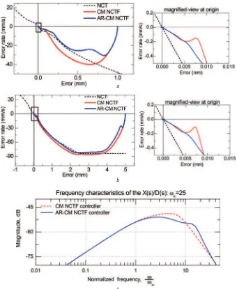
The total profile of the non-linear NCT and δ-block strongly influences the overshoot characteristics and the transient performances of a control system against height of step input. Since the NCT represents the deceleration trajectory of the mechanism to reach the origin, the move-ment of a mechanism to follow NCT and end at origin on phase plane will be useful to analyse the characteristic qualitatively. Figs. 4a–b illustrates the comparative trajec-tories on the phase plane of two NCTF control systems, and their magnified-views at the origin. The AR-CM and the CM NCTF controllers are tested in simulation step
responses at step inputs 1 and 5 mm with the controller parameters: ζ =0.565 and ωnT =0.183. The CM NCTF
controller makes the mechanism motion reach the NCT before the motion decelerates and follows the NCT insuffi-ciently. This will easily cause significant overshoot. On the other hand, the AR-CM NCTF controller makes the object motion follow the NCT quickly and accurately and end at the reference position. This phenomenon gives the system an advantage that leads to suppress the overshoot. As promised by the AR-CM NCTF controller, by using the acceleration reference characteristic trajectory (δ-block) in the control structure, the high following accuracy is improved.
In this paper, the improvement in positioning accuracy and the robust performance of the AR-CM NCTF con-troller is validated and discussed. Hence, it is important to address the disturbance rejection characteristic of the con-troller. Frequency characteristics of the linearised NCTF control systems described in Section 3.3 are examined to compare the disturbance rejection properties of the AR-CM and AR-CM NCTF control systems. Fig. 4c illustrates the
a
b
c
Fig. 4 Comparative trajectories on the phase plane and simulated frequency response (X(s)/D(s)) of the CM and AR-CM NCTF control systems
a Responses of the NCTF control systems on the phase plane to 1 mm step input in simulation
b Responses of the NCTF control systems on the phase plane to 5 mm step input in simulation
normalised-frequency, ω/ωn, against magnitude (decibels)
for both the NCTF control systems with the linear NCT from the disturbance to the displacement. The linear NCT is expressed as a straight line that is approximated incli-nation close to the origin of the NCT and the used ωn is
25 rad/s. The magnitude of the AR-CM NCTF control sys-tem in Fig. 4c is the same or smaller than the CM NCTF control system in the low normalised-frequency range to 10. It can be concluded that the AR-CM NCTF control system generally shows better robustness to a disturbance force.
4
Experimental performance
The usefulness of the AR-CM NCTF controller is experi-mentally evaluated using the mechanism with friction char-acteristics. Two types of motion control performances, that is, positioning and tracking performances, were experimen-tally examined. The AR-CM NCTF controller has been proposed to improve the overshoot reduction characteristics and tracking accuracy that are not sufficiently provided by
Table 2 Controller parameters
Controller βs−1 λs K
p Ki Kd
CM NCTF 110 – 0.25 10.12 –
AR-CM NCTF 110 0.003 0.25 10.12 –
PDDO-A – – 20.57 – 0.6
PDDO-B – – 70.57 – 0.5
the CM NCTF controller. Hence, the comparative exper-imental positioning and tracking performances of the two NCTF controllers are conducted and validated in this paper. Besides, the PDDO controllers are designed and com-pared with the AR-CM NCTF controller in order to evaluate their robust performances in the presence of mass and distur-bance changes. The mass of mechanism is increased twice times, whereas coulomb friction and the viscosity friction are increased four times and twice times, respectively. The PDDO controllers are designed under the condition that the linearised control systems have the same bandwidth as the linearised AR-CM NCTF control system. The PD gains are tuned to perform the same bandwidth as the AR-CM NCTF control system. Then, two poles of observer are adjusted experimentally. Owing to the limitation of the mechanism, the poles are set to−0.1 and−0.11. Two PDDO controllers are designed, namely PDDO-A and PDDO-B controllers. Besides the same bandwidth, the PDDO-B con-trol system is designed to have exactly the same frequency response as the AR-CM NCTF control system. Table 2 presents the controller parameters of the four controllers.
4.1 Positioning performance
Figs. 5a and b show the comparison of the experimental positioning responses of the four control systems: AR-CM NCTF, CM NCTF, PDDO-A and PDDO-B control systems to step inputs 1 and 5 mm with default mass. The step responses and their zoomed view of overshoot and motion errors are illustrated. As observed obviously, the PDDO-A controller shows almost identical positioning performance,
a b
b
c d
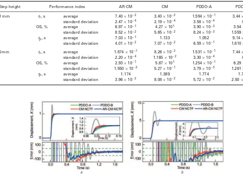
Fig. 5 Experimental step responses of the four control systems (increased mass object)
a Responses to a 1 mm step input (default mass)
b Responses to a 5 mm step input (default mass)
c Responses to a 1 mm step input (increased mass)
with no overshoot as compared with both the NCTF con-trollers. However, the PDDO-B controller (which has similar reference following characteristics to the AR-CM NCTF controller) produces extremely high overshoot at both step heights. When the step height is increased, it can be seen clearly that the AR-CM NCTF controller performs better in suppressing the residual vibrations as compared with the CM NCTF controller. Moreover, the AR-CM NCTF controller also takes shorter positioning time to reduce error<100 nm. ‘The AR-CM NCTF controller could make the object motion reach the NCT before the motion decelerates and follow the NCT more sufficiently than the CM NCTF controller’. These positioning results indicate the improvement in posi-tioning accuracy of the AR-CM NCTF controller. The major improvement of the AR-CM NCTF controller in over-shoot reduction and motion accuracy enhancement has been proved in point-to-point positioning.
The positioning responses with the increased mass are shown in Figs.5candd. The CM NCTF controller fails to demonstrate robust performance in response to the increase of mass, by producing a large overshoot. ‘This proves that the AR-CM NCTF controller shows lower sensitivity to disturbance than the CM NCTF controller, with lower magnitude in frequency characteristics (see Fig. 5c).’ The quantitative results in Table3 show that the averaged over-shoot of the CM NCTF controller are larger than 98% the AR-CM NCTF controller. Still, the PDDO-B controller yields a large overshoot. On the other hand, the AR-CM
NCTF and PDDO-A controllers are able to show its robust characteristic by maintaining the no overshoot response. The AR-CM NCTF controller does show better positioning accu-racy (≃10 nm), shorter rise time and positioning time to reduce error<100 nm. The experimental results indicate the strong robust performance of the AR-CM NCTF to mass variation.
The positioning responses with the increased friction force of four controllers are shown in Fig. 6. As observed, the PDDO-B controller shows the high robust performance and yields extremely high overshoot when friction force is increased at both inputs. Even though the PDDO-A con-troller does not produce any unwanted overshoot, but it takes too long positioning time to reach steady state. The aver-aged positioning time as stated in Table 4 shows that the AR-CM NCTF controller takes the shortest time to reduce error<100 nm. Overall, the AR-CM NCTF controller main-tains better positioning performance when friction force is increased to the mechanism.
4.2 Tracking performance
For tracking motion, sinusoidal reference inputs with two different amplitudes and frequencies are applied to command the mechanism with friction. The maximal tracking error is defined as max |xr−x|, wherexr is the reference input and
x is the displacement of the object. Besides, the root mean
Table 3 Positioning performances of five (5) experiments for four controllers (increased mass)
Step height Performance index AR-CM CM PDDO-A PDDO-B
1 mm tr, s average 7.40×10⁻² 3.40×10⁻² 1.594×10⁻¹ 3.44×10⁻²
standard deviation 2.47×10⁻⁴ 2.19×10⁻⁴ 3.58×10⁻⁴ 0
OS, % average 6.97×10⁻¹ 4.27×101 3.90×10⁻³ 3.54×101
standard deviation 8.52×10⁻² 5.65×10⁻² 8.24×10⁻³ 1.559×10⁻²
tp, s average 7.03×10⁻¹ 1.133 1.052 9.14×10⁻¹
standard deviation 4.01×10⁻² 7.07×10⁻² 6.59×10⁻¹ 1.810×10⁻¹
5 mm tr, s average 1.874×10⁻¹ 8.26×10⁻² 1.531×10⁻¹ 7.44×10⁻²
standard deviation 2.20×10⁻⁴ 1.165×10⁻² 3.30×10⁻⁴ 0
OS, % average 2.93×10⁻¹ 5.87×101 1.254×10⁻¹ 6.29×101
standard deviation 1.550×10⁻³ 5.27×10⁻¹ 3.79×10⁻³ 1.261×10⁻¹
tp, s average 1.174 1.389 1.774 1.799
standard deviation 3.96×10⁻² 8.08×10⁻² 5.72×10⁻² 2.50×10⁻¹⁶
a b
Fig. 6 Comparative experimental step responses of the four control systems (increased friction force)
a Responses to a 1 mm step input
Table 4 Positioning performances of five (5) experiments for four controllers (increased friction force)
Step height Performance index AR-CM CM PDDO-A PDDO-B
1 mm tr, s average 9.07×10⁻² 8.54×10⁻² 2.29×10⁻¹ 2.80×10⁻²
standard deviation 1.085×10⁻² 2.19×10⁻⁴ 2.34×10⁻² 1.790×10⁻⁴
OS, % average 1.567×10⁻¹ 2.89×10⁻¹ 8.65×10⁻¹ 3.16×101
standard deviation 2.40×10⁻³ 9.46×10⁻³ 3.59×10⁻² 1.093×10⁻¹
ts, s average 7.03×10⁻¹ 1.149 1.799 1.799
standard deviation 1.950×10⁻³ 7.89×10⁻² 2.50×10⁻¹⁶ 2.5×10⁻¹⁶
5 mm tr, s average 1.584×10⁻¹ 1.426×10⁻¹ 1.649×10⁻¹ 5.93×10⁻²
standard deviation 0 2.20×10⁻⁴ 4.40×10⁻³ 1.800×10⁻⁴
OS, % average 5.51×10⁻² 8.96×10⁻² 4.91×10⁻² 5.30×101
standard deviation 4.70×10⁻⁴ 9.50×10⁻⁴ 1.091×10⁻² 4.32×10⁻¹
ts, s average 1.127 1.106 1.799 1.799
standard deviation 5.07×10⁻² 5.77×10⁻² 2.50×10⁻¹⁶ 2.50×10⁻¹⁶
square (RMS) error (erms) is calculated as
1/NN k=1e2,
whereN is the number of data samples andestays for the tracking error. The adverse effect of friction on the track-ing performance of PDDO-A controller is obviously evident with large maximal tracking error (see Figs.7a–b). As com-pared with the PDDO-B controller, the PDDO-A controller cannot compensate the error effectively because of the fric-tion around the non-zero velocity. Although the PDDO-B controller has shown the similar small maximal tracking error as the AR-CM NCTF controller, but the RMS error
is three times larger than the AR-CM CNTF controller (see Table5). The AR-CM NCTF controller is obviously proved to show better motion accuracy (smaller maximal track-ing error) than the CM NCTF controller at reference input 50µm amplitudes and 1 Hz frequency (see Fig. 7b). The AR-CM NCTF controller reduces the tracking error ampli-tude by 37% as compared with the CM NCTF controller. ‘This proves the high disturbance rejection characteristics of the AR-CM NCTF controller, especially in low refer-ence motion frequency as discussed in Section 3.4’. The PDDO-B controller demonstrates smaller tracking error at
a b
c d
Fig. 7 Comparative experimental tracking responses of four types of controllers under two conditions of the mass
a Response to sinusoidal input: 1 mm, 0.5 Hz (default mass)
b Response to sinusoidal input: 50µm, 1 Hz (default mass)
c Response to a sinusoidal input: 1 mm, 0.5 Hz (increased mass)
Table 5 Average tracking results of five (5) experiments for four controllers (default mass)
max|xr−x| eRMS
Reference input Controller Average,µm Average,µm
sinusoidal AR-CM 1.264 2.25×10⁻¹
1 mm, 0.5 Hz CM 1.419 2.36×10⁻¹
PDDO-A 4.58 2.38
PDDO-B 1.498 7.42×10⁻¹
sinusoidal AR-CM 1.132 3.41×10⁻¹
50µm, 1 Hz CM 1.274 3.62×10⁻¹
PDDO-A 2.33 1.606
PDDO-B 9.00×10⁻¹ 5.67×10⁻¹
Table 6 Average tracking results of five (5) experiments for four controllers (increased mass)
max|xr−x| eRMS
Reference input Controller Average,µm Average,µm
sinusoidal AR-CM 1.695 2.78×10⁻¹
1 mm, 0.5 Hz CM 1.887 2.87×10⁻¹
PDDO-A 5.80 2.87
PDDO-B 1.774 8.33×10⁻¹
sinusoidal AR-CM 1.201 3.26×10⁻¹
50µm, 1 Hz CM 1.352 3.62×10⁻¹
PDDO-A 3.57 2.14
PDDO-B 1.092 6.39×10⁻¹
the shorter working range (50µm, 1 Hz), but shows larger RMS error than the AR-CM NCTF controller. The AR-CM NCTF controller could respond quickly to reduce error (near to zero) during the mechanism keeping the same direction, as compared with the PDDO-B controller.
When the mass of object is increased, the tracking errors of all the controllers are increased. In both tracking motions, the PDDO-A controller hits the largest tracking error among those controllers. As observed obviously in Fig. 7d, the increased mass makes the tracking error of the PDDO-B controller increase by ∼25%, whereas the AR-CM NCTF controller performs the smallest increment of tracking error,
with only an increase of 6.1% under the default mass condi-tion. Although the PDDO-B controller demonstrates smaller or similar tracking error than the AR-CM NCTF controller, however, the RMS error is still much larger than the AR-CM NCTF controller (see Table 6). In contrast, the PDDO controllers provide larger tracking errors than the NCTF controllers when the table keeps the same motion direction. It is evident that the quadrant glitches happen during the velocity near zero or motion reversal in both NCTF control systems.
Fig.8depicts the effect of the increased friction force on the tracking responses to two sinusoidal reference inputs. The tracking error of all the controllers increased with an increase of the friction force. As observed, the PDDO-A controller demonstrates the largest tracking error, but the incremental of maximal tracking error is smaller than the NCTF controllers, by comparing with the default condition. The AR-CM NCTF controller could reduce the error quickly to nearly zero when the mechanism keeps the same direc-tion in comparison with the PDDO-B controller although the later one shows smaller tracking error. The quantitative comparison is shown in Table 7. Although the PDDO-B controller demonstrates the smaller tracking error than the AR-CM NCTF controller, it produces the large overshoot in positioning. Overall, the AR-CM NCTF controller is able to perform consistent high positioning and tracking perfor-mances and the robust performance to the change of mass and disturbance force. However, it still does not yet achieve
Table 7 Average tracking results of five (5) experiments for four controllers (increased friction force)
max|xr−x| eRMS
Reference input Controller Average,µm Average,µm
sinusoidal AR-CM 7.57 1.330
1 mm, 0.5 Hz CM 8.48 1.409
PDDO-A 1.474×101 1.04×101
PDDO-B 4.75 2.99
sinusoidal AR-CM 5.42 1.713
50µm, 1 Hz CM 5.84 1.888
PDDO-A 1.14×101 8.87
PDDO-B 3.54 2.76
a b
Fig. 8 Comparative experimental tracking responses of four types of control systems under the increased friction force condition
a Response to a sinusoidal input: 1 mm, 0.5 Hz
the satisfactory level and is needed to improve the motion accuracy in the future.
5
Conclusion
In this paper, the framework of the AR-CM NCTF con-trol as a practical concon-trol approach to enhance the following characteristics and the experimental validation of the effec-tiveness has been presented. The AR-CM NCTF controller was applied to a linear motion mechanism with friction characteristics for evaluation of its effectiveness in position-ing, tracking control and robust performances. The AR-CM NCTF controller remains the advantage in the design proce-dure such as ease of use, high practicality and independence. The characteristics and stability of the AR-CM NCTF con-troller were discussed. The effectiveness of the AR-CM NCTF control system was verified in experimental studies including position and tracking control, and robust per-formances in comparison with the CM NCTF and PDDO controllers. To have a fair comparison, the AR-CM NCTF control system adopted the same NCT and PI compen-sator as the CM NCTF one and the PDDO control systems were designed so as to have the same bandwidth as the AR-CM NCTF control system. The robust performances of the controllers were examined with the change of mass and disturbance force. Overall, the AR-CM NCTF control system demonstrates superior positioning and robust perfor-mances over the CM NCTF one, in positioning and tracking controls. The experiment results are sufficient to prove the contribution of the AR-CM NCTF controller in performance enhancement including overshoot reduction and disturbance rejection characteristics. The AR-CM NCTF controller has performed high robust performance to mass and friction force changes in positioning and tracking. Although the AR-CM NCTF controller has assured superior performance among the compared controllers, complete removing of fric-tion effect for further improving the tracking accuracy will be done in the future work.
6
Acknowledgment
This research has been done in the Kaiji Sato Laboratory, Tokyo Institute of Technology, Japan.
7
References
1 Oiwa, T., Katsuki, M., Karita, M.et al.: ‘Questionnaire survey on ultra-precision positioning’, Int. J. Autom. Technol., 2011, 5, (6),
pp. 766–772
2 Wai, R.-J., Lee, J.-D., Chuang, K.-L.: ‘Real-time PID control strat-egy for maglev transportation system via particle swarm optimisation’,
IEEE Trans. Ind. Electron., 2011,58, (2), pp. 629–646
3 Kikuuwe, R., Satoshi, Y., Fujimotor, H.et al.: ‘Proxy-based sliding mode control: a safer extension of PID position control’,IEEE Trans. Robot., 2010,26, (4), pp. 670–683
4 Maeda, G.J., Sato, K., Hashizume et al.: ‘Control of XY nano-positioning table for a compact nano-machine tool’,J. Mater. Sci. Int. J. Ser. C, 2006,49, (1), pp. 21–27
5 Tan, K.K., Lee, H.L., Dou, H.F. et al.: ‘Precision motion control with disturbance observer for pulse width-modulated-driven permanent
magnet linear motors’,IEEE Trans. Magn., 2003,39, (3), pp. 1813–
1818
6 Katsura, S., Irie, K., Ohishi, K.: ‘Wideband force control by position-acceleration integrated disturbance observer’,IEEE Trans. Ind. Elec-tron., 2008,55, (4), pp. 1699–1706
7 Yang, Z.-J., Wang, Y., Kanae, S.: ‘New approach to an adaptive robust motion controller combined with a disturbance observer’,IET Control Theory Appl., 2011,5, (10), pp. 1203–1213
8 Xing, K., Huang, J., Wang, Y. et al.: ‘Tracking control of pneu-matic artificial muscle actuators based on sliding mode and non-linear disturbance observer’, IET Control Theory Appl., 2010, 4, (10), pp. 2058–2070
9 Lee, H.S., Tomizuka, M.: ‘Robust motion controller design for high-accuracy positioning systems’,IEEE Trans. Ind. Electron., 1996, 43,
(1), pp. 48–55
10 Guan, C., Pan, S.: ‘Nonlinear adaptive robust control of single-rod electro-hydraulic actuator with unknown nonlinear parameters’,IEEE Trans. Control Syst. Technol., 2008,16, (3), pp. 434–445
11 Zhu, X., Tao, G., Yao, B.: ‘Adaptive robust posture control of parallel manipulator driven by pneumatic muscle with redundancy’,
IEEE/ASME Trans. Mechatronics, 2008,13, (4), pp. 441–450
12 Yao, B., Al-Majed, M., Tomizuka, M.: ‘High performance robust motion control of machine tools: an adaptive robust control approach and comparative experiments’, IEEE/ASME Trans. Mechatronics, 1997,2, (2), pp. 63–76
13 Li, Z., Chen, J., Zhang, G., Gan, M.G.: ‘Adaptive robust control for DC motors with input saturation’,IET Control Theory Appl., 2011,5, (16), pp. 1895–1905
14 Juhasz, L., Maas, J.: ‘Control of hybrid nanopositioning systems for trajectory-tracking applications’,Mechatronics, 2013,23, pp. 617–629
15 Huang, Y.S., Sung, C.C.: ‘Implementation of sliding mode controller for linear synchronous motors based on direct thrust control theory’,
IET Control Theory Appl., 2010,4, (3), pp. 326–328
16 Shen, J.C., Jywe, W.Y., Chiang, H.K.et al.: ‘Precision tracking control of a piezoelectric-actuated system’,Precis. Eng., 2008,32, pp. 71–78
17 Lee, H., Utkin, V.I.: ‘Chattering suppression methods in sliding mode control systems’,Annu. Rev. Control, 2007,31, pp. 179–188
18 Li, P., Zheng, Z.-Q.: ‘Robust adaptive second-order sliding mode con-trol with fast transient performance’,IET Control Theory Appl., 2012,
6, (2), pp. 305–312
19 Maeda, G.J., Sato, K.: ‘Practical control method for ultra-precision positioning using ball screw mechanism’,Precis. Eng., 2008,32, (4),
pp. 157–169
20 Sato, K., Maeda, G.J.: ‘A practical control method for precision motion – improvement of NCTF control method for continuous motion control’,Precis. Eng., 2009,33, (2), pp. 175–186
21 Chong, S.H., Sato, K.: ‘Practical controller design for precision posi-tioning independent of friction characteristic’,Precis. Eng., 2010,34,
(2), pp. 286–300
22 Chong, S.H., Hashimoto, H., Sato, K.: ‘Practical motion control with acceleration reference for precision positioning motion – new NCTF control and its application to non-contact mechanism’,Precis. Eng., 2011,35, (1), pp. 12–23
23 Sato, K.: ‘Practical and intuitive controllers for precision motion: AR-CM NCTF control of ball screw mechanism’, Int. J. Autom. Technol., 2011,5, (6), pp. 793–798
24 Sato, K., Zheng, J., Tanaka, T., Shimokohbe, A.: ‘Micro/macro dynamic characteristics of mechanism with a harmonic speed reducer and precision rotational positioning control using disturbance observer’,Int. J. Jpn. Soc. Mech. Eng., 2000,42, (2), pp. 318–325 25 Kempf, C.J., Kobayashi, S.: ‘Disturbance observer and feedforward
design for a high speed direct drive positioning table’,IEEE Trans. Control Syst. Technol., 1999,7, (5), pp. 513–526
26 Kobayashi, H., Endo, S., Kobayashi, S., Kempf, C.J.: ‘Robust dig-ital tracking controller design for high speed positioning systems – a new design approach and implementation techniques’. Proc. IEEE Int. Workshop on Advanced Motion Control, Japan, 1996, vol. 1, pp. 65–370
27 Shin, J.H., Fujiune, K., Suzuki, T., Okuma, S., Yamada, K.: ‘Posi-tioning control of direct drive robot with two degree of freedom compensator’. Proc. IEEE Int. Conf. on Robotics and Automation, Nagoya, Japan, 1995, pp. 3137–3142