UNIVERSITI TEKNIKAL MALAYSIA MELAKA
FREQUENCY ANALYSIS TECHNIQUE FOR
DETERMINATION OF HIGH VOLTAGE INSULATION
MATERIAL SURFACE CONDITION
This report submitted in accordance with requirement of the Universiti Teknikal Malaysia Melaka (UTeM) for the Bachelor Degree of Engineering Technology
(Industrial Power) (Hons.)
By
MOHD KHAIRUL IDHAM BIN SAIDIN
B071210078
910602-06-5251
BORANG PENGESAHAN STATUS LAPORAN PROJEK SARJANA MUDA
TAJUK: Frequency Analysis Technique for Determination of High Voltage Insulation Material Surface Condition
SESI PENGAJIAN: 2015/16 Semester 1
Saya MOHD KHAIRUL IDHAM BIN SAIDIN
mengaku membenarkan Laporan PSM ini disimpan di Perpustakaan Universiti Teknikal Malaysia Melaka (UTeM) dengan syarat-syarat kegunaan seperti berikut:
1. Laporan PSM adalah hak milik Universiti Teknikal Malaysia Melaka dan penulis. 2. Perpustakaan Universiti Teknikal Malaysia Melaka dibenarkan membuat salinan
untuk tujuan pengajian sahaja dengan izin penulis.
3. Perpustakaan dibenarkan membuat salinan laporan PSM ini sebagai bahan pertukaran antara institusi pengajian tinggi.
4. **Sila tandakan ( )
SULIT
TERHAD
TIDAK TERHAD
(Mengandungi maklumat yang berdarjah keselamatan atau kepentingan Malaysia sebagaimana yang termaktub dalam AKTA RAHSIA RASMI 1972)
(Mengandungi maklumat TERHAD yang telah ditentukan oleh organisasi/badan di mana penyelidikan dijalankan)
__________________________
DECLARATION
I hereby, declared this report entitled “Frequency Analysis Technique for Determination of High Voltage Insulation Material Surface Condition” is the results
of my own research except as cited in references.
Signature : ... Author’s Name: MOHD KHAIRUL IDHAM BIN SAIDIN
APPROVAL
This report is submitted to the Faculty of Engineering Technology of UTeM as a partial fulfilment of the requirements for the degree of Bachelor of Electrical Engineering Technology (Industrial Power) with Honours. The member of the supervisory is as follow:
i
ABSTRACT
ii
ABSTRAK
iii
DEDICATIONS
iv
ACKNOWLEDGMENTS
Thank to Allah for giving me the opportunity in completing this report “Projek Sarjana Muda I” with success after when through the obstacle with patient. I would like to thank to my supervisor, Puan Nurbahirah binti Norddin for guiding me in completing this project and report. Many thing have she taught me and correcting what i has making wrong. Thanks to all lecturer and technician that have giving me a good knowledge and experience their have share in class and also in the lab session.
Thank to my beloved friend nur afifi and akmal hakim for help me in learning new software that I never used such as LABVIEW and MATLAB which is I used both software in my project. Thank you also to afiq, haider and fareq for sharing and comparing what my report a lack with it. Not forget to my academic advisor, En. Ahmad Idil Bin Abdul Rahman in helping me to understand more advance about MATLAB. He had help me a lot and his teaching skill very effective.
To my mother, Faridah binti Harun, a special thanks to her for giving me the opportunity to further study in degree. Without her permission and blessing, I would not be in this university and my degree project will not be done by me.
v
TABLE OF CONTENTS
ABSTRACT ... i
ABSTRAK ... ii
DEDICATIONS ... iii
ACKNOWLEDGMENTS ... iv
TABLE OF CONTENTS ... v
LIST OF FIGURES ... ix
LIST OF TABLE ... xi
LIST OF SYMBOLS AND ABBREVIATIONS ... xii
CHAPTER 1 ... 1
1.0 Introduction ... 1
1.1 Background ... 1
1.2 Problem Statement ... 2
1.3 Objectives ... 2
1.4 Scope ... 2
1.5 Project Significant ... 3
CHAPTER 2 ... 4
2.0 Introduction ... 4
vi
2.5 Principal Thermoplastic Polymers for Electrical/Electronic Uses ... 8
2.5.1 Polypropylene ... 8
2.5.1.1 Chemical Bond ... 8
2.5.1.2 Grades ... 9
2.5.1.3 Processing ... 10
2.5.1.4 Properties ... 10
2.5.1.5 Electrical/Electronic Uses ... 11
2.5.1.6 Incline Plane Test (IPT) ... 11
2.6 MATLAB ... 13
2.6.1 Fast Fourier Transform (FFT) ... 13
2.7 Leakage Current ... 15
2.7.1 Erosion Cause by Leakage Current ... 16
CHAPTER 3 ... 19
3.0 Introduction ... 19
3.1 Project Information ... 21
3.2 Simulation ... 21
3.2.1 Constructing Coding Using MATLAB ... 21
3.2.1.1 Fast Fourier Transform (FFT) ... 22
vii
3.3 Running the Experiment, Result, Analysis and Conclusion ... 26
3.4 Conclusion ... 26
CHAPTER 4 ... 27
4.0 Introduction ... 27
4.1 Result From IPT Test ... 27
4.1.1 Waveform from LabVIEW ... 28
4.1.1.1 Capacitive ... 28
4.1.1.2 Resistive ... 29
4.1.1.3 Symmetrical ... 31
4.1.1.4 Unsymmetrical ... 32
4.1.2 Simulate in MATLAB ... 35
4.1.2.1 Convert Excel File to MATLAB File ... 35
4.1.2.2 Capacitive ... 37
4.1.2.3 Resistive ... 39
4.1.2.4 Symmetrical ... 41
4.1.2.5 Unsymmetrical ... 43
4.1.3 Comparison ... 45
4.2 Discussion ... 46
viii
5.2 Conclusion ... 52
APPENDICES ... 53
ix
LIST OF FIGURES
Figure 2.1:Polyethylene ... 7
Figure 2.2: Polymonofluoroethylene ... 7
Figure 2.3: Polytetrafluoroethylene ... 7
Figure 2.4: Isomerism for positions in polypropylene: (a) tail; (b) head-to-head; (c) tail-to-tail.(Kocsis,1995) ... 9
Figure 2.5: Inclined Plane Test Apparatus (Heger et al., 2010) ... 12
Figure 2.6: Specimens Installed in the outdoor test station(Sampe et al., 2004) ... 13
Figure 2.7: Clean Signal Graph(Source:< http://hyperphysics.phy-astr.gsu.edu/hbase/math/fft.html> 27/05/2015) ... 14
Figure 2.8: Signal With Noise(Source:< http://hyperphysics.phy-astr.gsu.edu/hbase/math/fft.html> 27/05/2015) ... 15
Figure 2.9: Spark discharge occur on the Polypropylene during the IPT test,(Sulaiman & Abdullah, 2013) ... 17
Figure 2.10: Polypropylene before spark occurs... 17
Figure 2.11: Resistive type of Polymer’s Leakage Current,(Sulaiman & Abdullah, 2013) ... 17
Figure 2.12: Polypropylene after spark occurs ... 18
Figure 2.13: Discharge symmetrical of Polymer’s Leakage Current,(Sulaiman & Abdullah, 2013) ... 18
Figure 3.1: Flow Chart of Work ... 20
Figure 3.2: Illustration of window length and transform length ... 22
Figure 3.3: Example coding for FFT ... 23
Figure 3.4: Input Signal of the FFT ... 23
Figure 3.5: Fast Fourier Transform base on the coding above in Figure 3.3 ... 24
Figure 3.6: Block Diagram for capture Leakage Current using DAQ hardware ... 25
Figure 4.1: capacitive waveform ... 28
Figure 4.2: condition of capacitive LC ... 29
Figure 4.3: resistive waveform ... 30
Figure 4.4: condition of resistive LC ... 30
Figure 4.5: symmetrical waveform ... 31
Figure 4.6: condition of symmetrical LC ... 32
Figure 4.7: unsymmetrical waveform ... 33
Figure 4.8: condition of unsymmetrical LC ... 33
Figure 4.9: IPT test been run ... 34
Figure 4.10: flow of liquid contaminant on the surface. ... 34
Figure 4.11: LC occurred on the surface material... 35
Figure 4.12: Drag the excel file to the workspace on MATLAB ... 36
Figure 4.13: Set of data seen on MATLAB ... 36
x
Figure 4.20: FFT of resistive ... 41
Figure 4.21: Full data of symmetrical LC ... 42
Figure 4.22: Range data of symmetrical LC ... 42
Figure 4.23: FFT of symmetrical LC ... 43
Figure 4.24: Full data of unsymmetrical LC ... 44
Figure 4.25: Range data of unsymmetrical LC ... 44
Figure 4.26: FFT of unsymmetrical LC ... 45
Figure 4.27: motor that control the liquid drop ... 47
Figure 4.28: ammonium chloride ... 47
Figure 4.29: Triton X-100 ... 47
Figure 4.30: conductivity tester ... 48
Figure 4.31: electrodes and filter paper arrangement... 48
Figure 4.32: arrengment in lab ... 49
Figure 4.33: filter paper dimension ... 49
xi
LIST OF TABLE
xii
FFT = Fast Fourier Transform
TFD = Time Frequency Distribution
µ = Dipole moment
PO = Polyphenylene oxide
PP = Polypropylene
PS = Polystyrene
°F = Fahrenheit
°C = Celsius
IEC = International Electrotechnical Commission
IPT = Incline Plane Test
V = Voltage
DFT = Discrete Fourier Transform
IDFT = Inverse Discrete Fourier Transform
PSD = Power Spectral Density
TFR = Time Frequency Representation
Hz = Hertz
RTV = Room Temperature Vulcanized
HTV = High Temperature Vulcanized
HV = High Voltage
1
CHAPTER 1
INTRODUCTION
1.0 Introduction
In this section basically explain the background of this project and explaining the objective, the scope, problem statement and project significant.
1.1 Background
According to (Loom,1990), an electrical insulator is a material whose internal electric charges do not flow freely, and therefore make it very hard to conduct and electric current under the influence of an electric field. The other words, insulators which are used on electricity supply networks to support, separate or contain conductors at high voltage. Based on (Loom, 1990) a special case, the insulating tools which are used in the maintenance of live apparatus, is included because of the many features in common with classical insulators. Insulator made an important role in electricity. Without insulator people cannot handle electric current and it will cause casualties.
2
1.2 Problem Statement
Leakage current is the current that flows through the protective ground conductor to ground. In the absence of a grounding connection, it is the current that could flow from any conductive part or the surface of non-conductive parts to ground if a conductive path was available. Leakage current may cause erosion when it hit the material used as it cover. The erosion pattern is depend on the leakage current condition. In order to understand the erosion pattern on the material used, an analysis and an experiment will be done to study the pattern of the leakage current on the surface of the polymeric which is the insulation material that will be used in this project.
1.3 Objectives
The objective of this project are:
a) To compare the leakage current signal for material with erosion and without erosion on its surface.
b) To use Fast Fourier Transform (FFT) in determine the surface condition of material.
c) To identify the surface condition of insulating material based on quality of the signal.
1.4 Scope
3
been used to make the simulation of the leakage current. The erosion pattern in the insulation material will be compared.
1.5 Project Significant
4
CHAPTER 2
LITERATURE REVIEW
2.0 Introduction
This section will explain about the basic element that will be involve in this project such as leakage current, insulating materials, simulation used to simulate the waveform create by the leakage current and the chemical used for the project.
2.1 Insulator
An insulator very important when it involve in using current and voltage. It is also used to protect cable or wire or anything that need insulator from the current flowing outside the cable. Without insulator, living thing or people that touch the cable flowing with current can cause accident happen. Thus, an insulator is very important in giving protection to living thing and people.
5
2.2 Insulation System and Service Life
Base on (Shugg, 2002), an insulation system is an assembly of insulation materials in a particular type of equipment. Although there are other opinions on the subject among some authorities, this specification states the case for the determining service life of equipment as follows:
Based on the experience that has shown that the thermal life characteristic of composite insulation system cannot be reliably base on the information only. It must be support by testing it on real thing or known as accelerated life test. Accelerated life tests are being used increasingly to evaluate a new synthetic insulating materials that are available. Before it can be used with confidence shortening the period of service are required. The test that have been conduct and complete are necessary to confirm the performance of materials for their specific functions in the suitable equipment. Insulation equipment can be made up from different type of component. The component selected will be tested to withstand the different condition in electrical, mechanical and thermal stresses occurring in different part of the structure. The life of the insulation service will depend on tit effectiveness on supporting the current flow or forces acting on it. Therefore, the period of useful life of this system will depend on the arrangement of the components.
2.3 Material Aging and Breakdown
According to(Shugg, 2002), the factors that causing the aging and deterioration of an insulation are the following:
a) Thermal stresses occurring in electrical and electronic equipment. These are
cause by due to overloads of current plus the ambient temperatures or it can know as internal heating. When the material are exposing for prolonged periods above a temperature specific for each material, chemical breakdown rapidly accelerates.
b) Electrical stresses caused by the voltage gradient in the material. Most
6
techniques, centrifugal forces, and vibration. These stresses tend to physically damage material.
d) Environmental conditions, such as exposure to oxidation, ozone, radiation,
and chemicals. The resistance of insulating materials to many chemicals is well documented, so in selecting candidates for a specific application, only those materials should be considered that are resistant t encounter by chemicals.
The rate of voltage rise and is another factor of affecting dielectric strength and whether it is continuous or step by step. A slow rate of increase usually encourages time-dependent thermal degradation due to local heating, resulting in lower dielectric strength values. Dielectric breakdown strength values should include a statement of the following:
a) Specimen thickness and conditioning b) Method of voltage application
c) Type and size of electrodes d) Test temperature
e) Any unusual environmental conditions
2.4 Dipole Moment and Polarization
7
Dipole polarization occurs when normally randomly oriented permanent dipoles of a molecule are aligned by an applied electric field. This phenomenon is facilitated at higher temperatures where dipoles are bound less tightly and are freer to align with the field.
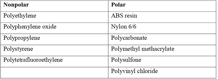
The type and arrangement of the atoms in a molecule determine its polarity. In general, the degree of molecular symmetry and the affinity of an atom for its electron influences polarity. Thus, polyethylene is nonpolar. Polymonofluoroethylene is strongly polar, and polytetrafluoroethylene exhibits low polarity (because of symmetry and the high affinity of fluorine for its electrons.
Figure 2.1:Polyethylene
Figure 2.2: Polymonofluoroethylene
Figure 2.3: Polytetrafluoroethylene
8
Polypropylene Polycarbonate
Polystyrene Polymethyl methacrylate
Polytetrafluoroethylene Polysulfone
Polyvinyl chloride
2.5 Principal Thermoplastic Polymers for Electrical/Electronic Uses
There are many type of thermoplastic polymers widely use nowadays, such as homopolymer, copolymer, terephthalate, polycarbonate, polypropylene and etc. For this project, polypropylene (PP) will be used as the insulator for testing.
2.5.1 Polypropylene
According to (Shugg, 2002), polypropylene is a highly versatile resin suitable for processing into moulded insulation parts, extruded wire and cable insulation, and dielectric films. Base on (Johnson.2015), one of the benefits of using this type of plastic is that it can be use in any application in the industry or in household. Others type such as a fiber-type plastic also useful.
2.5.1.1 Chemical Bond