DESIGN OF EMBEDDED PNEUMATIC CONTROLLER WITH PROPORTIONAL VALVE
WOON CHUN YAW
THIS REPORT IS SUBMITTED IN PARTIAL FULFILLMENT OF REQUIREMENTS FORTHE BACHELOR DEGREE OF ELECTRONIC
ENGINEERING (INDUSTRIAL ELECTRONIC)
FACULTY OF ELECTRONIC AND COMPUTER ENGINEERING (FKEKK) UNIVERSITI TEKNIKAL MALAYSIA MELAKA
Design of Embedded Pneumatic Controller with Proportional Valve
1 5 / 1 6
WOON CHUN YAW
iii
“I hereby declare that the work in this project is my own except for summaries and quotations which have been duly acknowledge.”
Signature : ...
Author : WOON CHUN YAW
iv
“I acknowledge that I have read this report and in my opinion this report is sufficient in term of scope and quality for the award of Bachelor of Electronic Engineering (Industrial
Electronics with Honours.”
Signature : ... Supervisor’s Name : Dr. Khairuddin Bin Osman
v
Specially dedicated to my beloved parents, the one and only
Woon Wee Leong and Yong Aik Lan,
as well as my whole family who have support and inspired me
vi
ACKNOWLEDGEMENT
vii
ABSTRACT
viii
ABSTRAK
ix
TABLE OF CONTENTS
CHAPTER TITLE PAGE
DECLARATION iii
APPROVAL iv
DEDICATION v
ACKNOWLEDGEMENTS vi
ABSTRACT vii
ABSTRACK viii
TABLE OF CONTENT ix
LIST OF FIGURES xi
LIST OF ABBREVIATIONS xiii
1 INTRODUCTION 1
1.1 Research Background 1
1.2 Problem Statement 3
1.3 Research Objectives 3
1.4 Scope of Work 3
2 LITERATURE REVIEW 4
2.1 Introduction 4
2.2 Pneumatic Actuators 4
2.3 System Identification and Controller Selection 9
2.4 Arduino Board 13
x
3 RESEARCH METHODOLOGY 18
3.1 Introduction 18
3.2 Research Process Flow 18
4 DESIGN, CONSTRUCT AND ANALYSIS 21
4.1 Introduction 21
4.2 Hardware design 21
4.2.1 Circuit design 21
4.2.2 Constructed prototype 25
4.3 Software Design 27
4.3.1 Interface using Arduino IDE 27
4.3.2 Coding development 30
4.4 Real-time Test and Analysis 35
5 CONCLUSION AND FUTURE WORKS 39
5.1 Conclusion 39
5.2 Suggestion for future works 40
xi
LIST OF FIGURE
Figure 2.1 Diagram of pneumatic actuator --- 4
Figure 2.2 Active icosahedron using intelligent cylinders --- 7
Figure 2.3 Intelligent pneumatic actuator and its parts --- 8
Figure 2.4 Implementation of IPA in PASS --- 8
Figure 2.5 Arduino Board --- 14
Figure 2.6 Arduino IDE --- 14
Figure 2.7 Arduino Board Family --- 15
Figure 2.8 Encoder Sensor --- 16
Figure 2.9 Block Diagram of Encoder Sensor --- 16
Figure 2.10 Output waveform of Encoder sensor --- 17
Figure 3.1 Model development flow chart --- 19
Figure 4.1 Block diagram of designed embedded system --- 21
Figure 4.2 Circuit’s Schematic for designed embedded system --- 22
Figure 4.3 Designed circuit using Proteus --- 23
Figure 4.4 Fabricated designed circuit --- 23
Figure 4.5 Fabricated circuit with soldered componenets --- 24
Figure 4.6 Fabricated circuit as an Arduino shield --- 24
Figure 4.7 Pneumatic actuator --- 25
Figure 4.8 Shield for pneumatic actuators --- 25
Figure 4.9 Constructed prototype --- 26
Figure 4.10 Arduino IDE --- 27
Figure 4.11 Serial Monitor --- 27
Figure 4.12 Serial Monitor with sensor reading of line’s number --- 28
Figure 4.13 Serial Monitor with sensor in length reading --- 29
Figure 4.14 Coding’s Flow Chart at initial state --- 30
Figure 4.15 Coding’s Flow Chart at Step A --- 31
Figure 4.16 Coding’s Flow Chart at Step C--- 32
xii
Figure 4.18 Prototype connected with air flow controller valve and air supply -- 35
Figure 4.19 Pneumatic actuator at initial position --- 36
Figure 4.20 Pneumatic actuator extracted to 5cm --- 36
Figure 4.21 Pneumatic actuator extracted to 7.5cm --- 37
Figure 4.22 Pneumatic actuator retracted to 3.2cm --- 37
xiii
LIST OF ABBREVIATIONS
ARMA Auto-Regressive Moving-Average
CAD Computer Aided Design
CAM Computer Aided Manufacturing
CARMA Controlled Auto-Regressive Moving Average
DMC Dynamic Matrix Control
EPVA Electro-Pneumatic Valve Actuator
GPC Generalized Predictive Control
HME Human Muscle Enhancer
IDE Integrated Development Environment
IPA Intelligent Pneumatic Actuator
ISAC Intelligent Soft Arm Control
LED Light Emitting Diode
MAC Model Algorithm Control
MGA Modified Genetic Algorithm
MP Myo-Pneumatic
MPC Model Predictive Control
xiv
MRI Magnetic resonance imaging
PAM Pneumatic Artificial Muscle
PASS Pneumatic Actuator Seating System
PFC Predictive Functional Control
PI Proportional-Integral
PID Proportional-Integral-Derivative
PLC Programmable Logic Controller
PRBS Pseudo Random Binary Sequence
PRSD Planetary Roller Spindle Drive
PSoC Programmable System on a Chip
PWM Pulse width modulation
RLS Recursive Least Squares
SI System Identification
1
CHAPTER 1
INTRODUCTION
1.1 Research Background
An actuator is a simple, specific component of machine functions as driving or controlling a mechanism or system. A pneumatic actuator perform mechanical motion either in rotary or linear motion with compressed air as the source. Pneumatic actuating system is one of the popular system chosen in industrial. Compared to hydraulic actuators, pneumatic actuator which is safer and more reliable has benefit in smaller size, fast response and withstand at high temperatures. Some specific condition environment such as nuclear environment, pneumatic actuator is more advantaging compared to hydraulic actuator. This is due to gases not subjected in temperature limitation the characteristic in pneumatic systems that cause them preferred in difficult environment is because gases does not have the limitation of temperature compared to liquid fluids. Furthermore, exhausted gases from the actuators can be ignore, hence the designation for return lines or the storage for fluid can be ignored because pneumatic systems are virtually dry and have no organic materials.
2
Actuator Seating System (PASS). The IPA system is a new important research with targeted to combine actuators, microprocessors, and various sensors.
Recently pneumatic actuators mainly focus used in industrial equipment and research in development of new pneumatic actuators. Industrial applications involved with pneumatic actuator included food packaging, construction robot, jack hammer and power drill and blow molding. Pneumatic actuators also implemented in medical field such as rehabilitation system, haptic physical human interface and needle positioning for magnetic resonance imaging (Ali. et al., 2009). It is hard to control the pneumatic actuator to achieve the expected output because the output is not directly proportional to the input. The main issues faced in developing pneumatic actuator is the dynamic behaviour which cause nonlinearities and uncertain characteristic. Moreover, most of the researchers focus on position control but do not solve the issue of the force control and compliance control.
In this project, IPA system has been chosen as main reference as it is the latest technology that developed the idea all-in-one mechanism which included many new feature for compact systems. Currently, the system implemented with simple Proportional-Integral (PI) controller design through the trial and error method. There are other disadvantages for control performances such as slow response, time delay, overshoot issues and stretch back not functioning with lower stiffness parameter.
3
1.2 Problem Statement
Pneumatic actuator generally used in many application of industry. It has the advantage of reliable, fast acting with high accelerations, low cost, flexible in installation, easy for maintenance, and free from overheating in the case of constant load However, current system used to control pneumatic actuator which is PLC control system is complexity. PLC system required many space and wiring for instalment. Using pneumatic also has the issue of unable to control the position of the piston. Hence, these cause pneumatic actuator only can implemented on certain industrial application and process.
1.3 Research Objectives
The followings are the objectives of this project:
To develop an embedded system for pneumatic actuator.
To control the retracted or extended position on pneumatic actuator. To design an interface for communication between computer and Arduino.
1.4 Scope of Work
The following are the scopes of the project:
4
CHAPTER 2
LITERATURE REVIEW
2.1 Introduction
In this chapter, past literature of pneumatic and Intelligent Pneumatic Actuator (IPA) system is reviewed. The review also will the introducing of System Identification (SI) and controlled technique in past research
2.2 Pneumatic Actuators
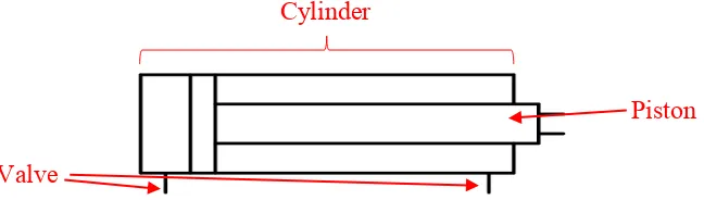
Pneumatic actuators is one of the most popular types of actuators used for automation applications especially in industries. Pneumatics in Greek means "breath", one of the physics applied to technology which makes use of gas or pressurized air. Pneumatic system has recently widely used in the applications for simple speed control in industrial process and automation such as in industrial manipulators and robotics. A basic pneumatic actuator made up from a piston, a cylinder, and valves (Plattenburg, 2005).
Figure 2.1 Diagram of pneumatic actuator
Piston
Valve
5
Basically, there are three types of pneumatic actuators: linear actuators, rotary actuators and pneumatic motors. Development of pneumatic actuator mainly focus on increasing the efficiency, improving the power-to-weight ratio, and construction rationalization, as well as proposing new types of devices. There are three type of actuator chose for linear motion application, which include pneumatic cylinder, a diaphragm actuator, or an actuator with bellows. Examination of the specification of the actuators required as the feature and design factors are different for each linear actuator (Dan et al., 2007; Ahn and Yokota, 2005; Rahmat and Kamaruddin, 2012).
Encoder sensors implemented in pneumatic actuators that use in a robotic manipulators in controlling the position using pneumatic actuators has been proposed by Chua et al. (2003). Gurley Model 8710 with 9,000 optical lines will generate 720,000 counts per revolution with 20:l interpolation of the sinusoidal output used. These based on the gripper mounted on a 100 mm radius arm with the resolution of 0.9 μm. Pressure sensor is used in control pressure by using the closed solenoid valve. Wang et al (2010) had proposed the idea of design a magnetic resonance imaging (MRI) compatible pneumatic actuator regulated by a piezoelectric valve for image guided robotic intervention. The proposed system include computer, a servo board, a converter, two piezoelectric pressure regulated valves, two pressure sensors, a force sensor and an encoder. The linear optical encoder used generated resolution of 2000 counts per inch (0.01 mm precision) with quadrature mode, which is suitable for the 0.1 mm accuracy requirement.
6
control to drive the position control of joint. It is known that such actuators contain high nonlinearity, including a hysteresis. The real muscle pressure measured using external pressure sensors to remove time delays or pressure loss due to long tubes. Two force sensors place between the end of the muscles and the test bed fram to measure the resulting torque.
Dan et al. (2007) proposed the first pneumatic stepper and the first MRI-compatible motor, the Pneumatic step motor (PneuStep) in their research. The motion of motor controlled with the optical encoding. Control algorithms with various feed-forward terms and saturation functions used to determine the stepping frequency and direction for common stepper motion control cards based on encoder feedback. This new motor has the benefit in easier of control in precise motion. Somehow, PneuStep’s drawbacks can only applied on specific class of application due to include its discrete positioning.
Intelligent actuator bring a new era in developing the pneumatic actuator as it is a new field of research that combined actuators, microprocessors, and various micro sensors together. These actuators able to communicate with PC, the complexity of wiring and cabling highly reduced, and have more delicate and high performance actuator motions. Strickland et al. (1992) is the first research in develop intelligent actuator where their research focused on the development of the actuators and highlighted new approach of designing servo systems. Comparison of control and fault tolerant software, communication links, micro-controller, sensor system and actuator be done through the development. They able to build up the intelligent servo system for robotic system with the help from Computer Aided Design (CAD) or Computer Aided Manufacturing (CAM) facility, ‘SERVOCAM’ and the result obtain show the approach is feasible.
7
50 x 50 x 104 mm (length x width x height). Designed compact microcontroller with stand-alone system allowed the actuator to drive the system.
The implement of an intelligent actuator in construction of a servo mechanism has proposed in research of Suzumori et al. (2005). Their research successfully control the position and the speed of the intelligent actuators. This newly improved intelligent actuator able to control positions of the actuator rod with a built-in encoder. The actuator with its 133 mm long and stroke of 40 mm, has the maximum positioning resolution of 338 μm. The speed of the positioning control and convergence in any position able to control with the implementation of servo system. By using the developed active link mechanism physical human-machine interaction (Ochi et al., 2004) enhanced by using with the intelligent actuators. Developed intelligent cylinder consist of 4 chambers to provide the high ratio of expansion and contraction during supply of air pressure into each chamber. Two optical encoders and a Light Emitting Diode (LED) are used to measure the length of the piston by detecting the guide rod stripes for the intelligent cylinder. The system included three type of communication protocols, USB, SPI, and I2C which is controlled by using Programmable System on a Chip (PSoC) chip. The control system was developed for the active icosahedrons in order for the control program perform the drawing of a virtual model on display and control of active links. The active icosahedrons performed the dynamic interaction with virtual objects in computer and prove the potential of the devices as a haptic interface.
8
Figure 2.3 Intelligent pneumatic actuator and its parts[14]
New Intelligent Pneumatic Actuator (IPA) designed and built by Ahmad 'Athif Mohd Faudzi (2010), Faudzi and Suzumori (2010), Faudzi et al. (2009), and Faudzi et al. (2010) referring the research by Ali et al. (2009) and Rahmat et al. (2011) in modelling and controlling strategies. This IPA able to solve the limitations of control devices due to low accuracy and force. The IPA is implemented as application in a Pneumatic Actuator Seating System (PASS). The specials of this IPA is the all-in-one ideas in where the suitable of sensors and valves chosen for designed within the actuator. This made it a novel for the development of pneumatic actuator. The microcontroller be the brain in drive the system and perform the control objective to implement into any related applications.
9
2.3 System Identification and Controller Selection
Many methods have been suggested to control the real industrial plant (Smaoui et al., 2008). Three man characteristics which is the basic forming mathematical modeling pneumatic system, that is Piston-Load Dynamics, Model of the Cylinder Chambers and Valve Model proposed to solve the unknown parameters in System Identification (SI) and linearize the system from mathematical model drawback. (Ali. et al., 2009; Richer and Hurmuzlu, 2000a; Richer and Hurmuzlu, 2000b; Ying et al., 2007; Rahmat et al., 2011; V. and M., 2007; Yong and Barth, 2005; Tressler et al., 2002; Krivts and Krejnin, 2006; Ali et al., 2009). The transfer function for plant system also determined using the proposed system with the measured experimental data. The uses of transfer function had become widely used in many field which included in engineering field, computer science field, financial sector, industrial applications and many others (Lianzhi and Weichong, 2012; Fei et al., 2011; Gorissen et al., 2011).
The servo valves and system response applied with input signals such as Pseudo Random Binary Sequence (PRBS). Data collected were digitally processed and created input-output data for identification models with the research since 1930’s (Zorlu et al., 2003). The modeling, identification and control of a two-joint planar Pneumatic Artificial Muscle (PAM) manipulator actuated by two groups of antagonistic PAM pairs was shown by (Kyoung Kwan and Ho Pham Huy, 2006). The research paper provided the modeling and identification of the robot arm, PAM manipulator Auto-Regressive enhancement with Exogenous Input (ARX) model's parameters based on the novel proposed the method of Modified Genetic Algorithm (MGA). A simple with high efficient of ARX model formulated by the researcher enable it is suitable for online parameter self-tuning control (the highly nonlinear 2-axes PAM manipulator).
10
the Auto-Regressive Moving-Average (ARMA) model with the implemented Mixed-Reality Environment (MRE) to avoid the complexity associated with nonlinear system modeling. With the proposed method, online system identification able to perform more effectively and efficiently. Matoušek (2011) further the research and determined the important of obtaining the order of the numerator and denominator of the system transfer for the online identification of the pneumatic positional servomechanism. This research also explain the two main parts that will affecting an adaptive control. The first part was explaining the design of an optimal structure of mathematical model that allows continuous identification. The second part show the design of an adaptive space-state controller by implement the adaptive control.
Adnan et al. (2010), Rozali et al. (2010), and Ling et al. 17 (2011) proposed other system identification technique, controller design and applications on sensing. The transfer function generated through system identification using the System Identification Toolbox in MATLAB and applied to hydraulic system. This method improved the accuracy of the model and was shown that time for data collection reduced. The objective of this thesis is to suggest a system identification method using ARX model and controller instead of linear model in order to enhance performance for IPA system.
![Figure 2.2 Active icosahedron using intelligent cylinders [54]](https://thumb-ap.123doks.com/thumbv2/123dok/474854.51956/21.612.210.438.511.678/figure-active-icosahedron-using-intelligent-cylinders.webp)
![Figure 2.3 Intelligent pneumatic actuator and its parts [14]](https://thumb-ap.123doks.com/thumbv2/123dok/474854.51956/22.612.210.443.517.654/figure-intelligent-pneumatic-actuator-and-its-parts.webp)
