Development
and
Performance Evaluation
of
area where the farming activity should be done at high slopeland. The main problem of farming activity in slope land is high soil erosion. Applying terrace-farming system can reduce this problem. However, constructing terrace system is a big deal for the farmers in area due to high cast if they hire commercial construction as well as a
hard work and consuming if they construct it manually. A huge swamp area in Indonesia is converts to
wet land rice field but lack of worker to cultivate the land
in the outer island of java. Application of field machineries is the only way to solve the worker problem. In relation with low bearing capacity of swampland, application of field machinery should be low ground pressure
type. Therefore, a small size and economically affordable construction machine like a mini needs to be
developed for constructing terrace system in rural area as
well as cultivate swampland. The aim of this research was to
develop a rubber track mini bulldozer by utilizing used hand tractor as prime mover.
Materials
and
MethodsThe functional and structural design approaches are in the methodology of developing the mini bulldozer. The design criteria in developing the mini-bulldozer were simple in construction and easy in operation and maintenance. The locally made hand tractor (Perkasa,
was used the base for developing the bulldozer. Firstly, the traction device of hand tractor was modified in to the rubber track. Secondly, the rubber tracked
hand tractor was attached with hydraulic system, dozer
blade and control system. Finally, the performance of bulldozer was evaluated.
A. Functional Design.
The developed mini-bulldozer was designed to have several functions hydraulic
system,
undercarriage, straight-blade and controlsystem.
Hydraulic system isundercarriage has function for transmitting the engine power to the traction power. Straight Made is used for cutting bulldozing the soil. Control system was design for
controlling the bulldozer including speed, direction, steering
and blade movement. B. Structural
The structure of hydraulic system consists of hydraulic pump, valves, actuator, and reservoir. The hydraulic pump was driven by the engine power with v-belt transmission.
The actuator was a double action hydraulic cylinder, which
was controlled by three way directional control vatves. The
undercarriage consists of frame, brake system, traction drum and idler and the rubber The engine and transmission of hand tractor were kept as the prime mover of the bulldozer.
The mini-bulldozer was constructed at the Farm Laboratory, Department of Agricultural Engineering, Agricultural University. The functional and performance test and evaluation were conducted to the prototype of mini-bulldozer in term of its dozing and maneuverability.
Results
and
Discussion1 , showed the
process
of developing handtractor based mini-bulldozer. In the first step is replacing the iron the hand tractor (Fig. with
the rubber track (Fig. .b) in order to improve the tractive ability of the hand tractor, especially for operation in
low
soil bearing capacity. In this step, design and construction of the were fitted with the transmission box andcontrol vahe
Pressure
F.
Filter
I
Figure 2. The hydraulic system for mini-bulldozer
The hydraulic system (Fig 2) was a controlled loop
adaptive self-tuning 1995). The hydraulic
system
was tested based on ASAE standard (ASAE andthe shows that the static and dynamic hydraulic
was found to be 4905 N and 4.46 respectively. This hydraulic force is sufficient to operate the bulldozer blade, where lifting force requirement is only 2500 N.
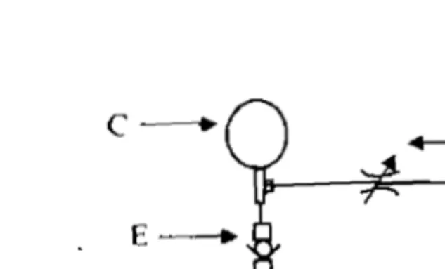
Figure 3. system of mini-bulldozer
Control system (Fig. 3) was designed and tested ergonomically
where
the location of each control lever canTam:
The straight blade was attached to the
(Fig. where angle of blade can adjusted from to (Fig. 3.b.) in order to allow soil movement to the left or the right side of the mini-bulldozer. The width and height of bulldozer blade were 1.3 m and 0.35
m Based an the
maximum
pull of themini- bulldozer it was predicted that the of cutting
depth was 2.5
cm,
while the optimum cutting angle of theblade was found to be From the performance test, it
was that the prediction of cutting depth was close
to the field test where the cutting depth of 2.5 cm gave a
maximum dozing volume (Fig 3 c.). average volume of
bulldozed soil was found to be 0.165 m at 0.06 forward speed. The relation between cutting depth, speed
and volume is shown in Fig. 4.
Figure Bulldozer blade
i
Cutting 'I ... ..
Figure 4. Relationship between cutting depth, forward speed and dozing volume
Conclusion
The results of performance test revealed that the mini bulldozer could work satisfactorily for soil as well
as for soil process. The average forward speed was found to be 0.06 and the average volume of dozed soil
References
Anonym, Caterpillar Handbook. 1 ed.
Caterpillar Tractor Co., Illinois, USA.
W. 1995. Addison Wesley England.
HD. 1999. Pengantar Perancangan Teknik
(Perancangan Pendidkan Tinggi
Pendidikan
Liljedahl, JB, PK DW Smith and M Hoki. 1989. Tractors and Their Power Units. Fourth Edition. An Books. New York, USA.