accredited by DGHE (DIKTI), Decree No: 51/Dikti/Kep/2010 291
RS-485 Bus Design of a Missile Simulation Training
System
Xinjie Ji, GuozhouWang, FangLiu
Department of Aeronautical Ammunition Engineering, The First Aeronautical College of Air Force Xinyang, China
e-mail: [email protected], [email protected], [email protected]
Abstrak
Pada sistem simulasi pelatihan rudal yang memiliki struktur terdistribusi dengan master-tunggal (one-master) dan slave-jamak(multi-slave), dibutuhkan suatu kontroler universal karena sistem itu terdiri dari beberapa kontroler. Dalam penelitian ini, kontroler-kontroler yang dirancang berkomunikasi dengan kontroler lain serta komputer pengontrol level di atasnya melalui komunikasi RS-485 field bus. Penelitian ini menyediakan proses perancangan bus RS-485, termasuk sirkuit antarmuka, protokol transmisi, metode Cyclic Redundancy Check (CRC) dan perangkat lunak penguji pengontrol. Kontroler universal yang mengadopsi sirkuit antarmuka RS-485 dirancang terhubung dengan twisted-pair sehingga membentuk sistem simulasi, kemudian kontroler itu diuji. Hasil pengujian menunjukkan bahwa dengan menggunakan protokol transmisi dan metode CRC tersebut, bus RS-485 dapat mengkomunikasikan secara efektif dengan laju transmisi data yang stabil mencapai 115.2 kbps.
Kata kunci:pelatihan simulasi, bus RS-485, protokol transmisi, CRC, kontroler universal
Abstract
In a missile simulation training system with one-master and multi-slaves distributed system structure, a universal controller is necessary due to the system composed with several controllers. In this research, the designed controllers communicate with each other and upper control computer through RS-485 field bus. RS-RS-485 bus including interface circuits, transmission protocol, Cyclic Redundancy Check (CRC) method and upper control test software is designed and proposed. The universal controller adopting the designed RS-485 interface circuits is connected through twisted-pair and makes the simulation system, then the controller is tested in line. The results show that the RS-485 bus communicates effectively using the protocol and CRC method, data transmission rates reaches 115.2 kbps, and has a good stability.
Keywords: simulation training,RS-485 bus, transmission protocol, CRC, universalcontroller
1. Introduction
The missile simulation training system is one complex system which includes many distributed units sampling much flux state signal of the tested missile, such as voltage signal, control signal, feedback state signals and so on, at the same time, outputs the right control signals to the missile. The signals transmission among the units must be have higher reliability and transmission speed. So the appropriate bus is the first step for designing one missile simulation training system.
In recent years, RS-485/422 [1-2], CAN-bus [3], PROFIBUS [4-5] and other bus are used in distributed system in China [6-7]. RS-485 bus and CAN bus adopt twisted-pair transmitting balanced differential signals, so it can get good ability of transmission distance, data rates and anti EMI (Electro Magnetic Interrupt). RS-485 standard data transmission rates reaches 10 Mbps, transmission distance reaches 4,000 feet at 100 kbps data rates, supports 32 nodes bi-directional communication. The PROFIBUS defined with the international standards (IEC61158, EN50170) allows a maximum of 200 or 400 m distance and the speed of 500 kbps [4].This research uses the RS-485 field bus connecting several universal controllers and constructing the distributed system.
of the RS-485 bus interface circuits. Chapter 4 explains the RS-485 bus protocol including data frame format and CRC method. In order to test the bus and protocol, the universal controllerand upper computer test software is given in Chapter 5. Furthermore, the results and discussion are described in Chapter 6 and concluded thereafter.
2. Bus Network Topology of the Missile Simulation Training System
The simulation training system includes upper control computer, air pressure altitude meter, wireless altitude meter, engine control unit, simulation target control unit, radio signal transceiver control unit and others. The units are connected though RS-485 bus in chain network topology as Figure 1. In this topology, the upper control computer serves as the control host, the other units as slaves. Thus, the upper computer is connected by bus line in series. When the simulation training system starts working, the host communicates with slaves according to the bus lines and transmission protocol. So the topology can work in master-slaver mode or multi masters mode.
Figure 1. Simulation training system network topology
3. Bus Interface Circuits Design
Interface circuits play a key role for RS-485 bus. The interface circuits design includes RS-485 driver chip selection, isolation circuit design, shunting circuits design and biasing resistor calculation.
3.1. RS-485 Driver ChipSelection
RS-485 driver chip converses the transceiver signal to satisfy the RS-485 bus standard, that is, according to the standard, the driver will produce a voltage from 2 to 6 voltages across A and B output terminals as Figure 2. During selection of driver chip, transceiver numbers on the bus, ability of against electrostatic discharge shocks (ESD), data transmission rates and pin counts. In the bus interface circuits use MAX483E ESA, designed as component U3 in Figure 2, working as driver chip. In Figure 2, the net RD/WR is control signal to enable or disable transceiver.
3.2. Isolation Circuit Design
MAX483E ESA chip can against ±15 kV ESD. But to make the interface circuits have a higher ability of transient protection and protect the micro control unit (MCU) device, adoption of isolation circuits is the most universal approach. Optical isolators, transformers and fiber optics are commonly used methods in many types of networked fieldbus. In this RS-485 bus interface circuits in Figure 2, the 6N137 optical isolator is used for isolation circuits design.
3.3. Shunting Circuits Design
U7 6 N1 3 7 G4 8 5 design bias resistor R36 and R39 to force the data lines to the idle state. Bias resistor R39 is a pulldown resistor to ground on the data line B, R36 is a pullup resistor on the data line A. Figure 2 illustrates the bias resistor placement of the interface circuits. The resistor value is different according to the topology with termination resistor R37 or without termination resistor R37. In this design, the R37 is not used in order to minimize the bias current. The bias resistor value calculation is based on
Rbias<VAB, min×Nnode/Rchip-Rchip/Nnode (1)
Rbias refers to the total value of the bias resistors, VAB,min the minimum voltage of the data line A and B, Rchip the resistance value of the driver chip, Nnode the numbers of the nodes on the bus. In this paper,VAB,minis 200 mV,Rchipis 12 kΩ . The calculation result ofRbiasis 9 kΩ or less referring toequation (1). The total value is spitted among all the nodes. So resistance value of the bias resistor is set 4.7 kΩ .
4. Transmission Protocol Design
The bus adopts a chain topology connecting the other nodes to the host computer, and composing the one master and multi slaves system. In this topology, the upper computer sends commands to and receives data from the slaves. The slaves receive commands from the host and make some response to the host. When the bus is idle, the slaves supervise the bus state at all times after the slave controller ispowered on. In case turning over from idle condition, means the data is transmitted on the bus. After that, the controller which gets the data will analyze the received data and commands along the transmission protocol.
4.1. Frame Format
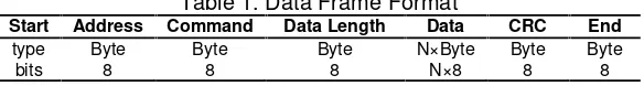
The transceiver data between host and slaves are data frames. The frame format is the base of different field bus. This research adopts the designed frame format as shown in Table 1. The data frame is constituted with frame start byte 0x55, address byte of receiver, command byte, sent data length byte, data bytes, CRC byte and frame end byte 0xAA. On account of the length of the Data Length Field is 8 bits, the maximum length of the transmitted data is 255 bytes per frame.
Table 1. Data Frame Format
Start Address Command Data Length Data CRC End
type Byte Byte Byte N×Byte Byte Byte
bits 8 8 8 N×8 8 8
4.2. CRC method
A CRC code is used by many communications protocols for packet error detection [8]. Now, 8-bits, 16-bits, 24-bits and 32-bits CRC and other CRC methods [9,10] are widely used in industrial fieldbus. This paper adopts 8-bits CRC method [11], whose polynomial is equation (2).
X8+X5+X4+1 (2)
The CRC code of CRC-8 method is hex value of 0x31. Sets one variable to store the CRC result, CRC program calculates the CRC result from frame address byte to frame CRC byte for the receiver, and calculates the CRC resultfrom frame address to frame data bytes for the sending controller, after that, puts the result to the position of CRC byte of the frame. Thus, when the CRC result equals to the received frame CRC byte, the CRC passed. Then the host or slave controller responds the frame command. If the variable to store CRC result is setcrc, the CRC function is written in Pascal language in Figure 3.
Figure 3. CRC function using Object Pascal
5. Test Software and Universal Controller
The universal controller adopting the designed interface circuits and protocol of RS-485 filed bus is placed in different units of the missile simulation training system.And the twisted-pairs connect the units to the upper control computer as shown in Figure 1. So, design one test software to test capability and stability of the universal controller based on the RS-485 field bus.
5.1. Upper Computer Test Software
The upper computer sends the frame including the address of target slave controller and command to the bus lines. The entire slave controllers supervise the bus lines, CRC and decode the frame according to the transmission protocol. In order to verify the protocol, one upper computer test software is designed in Delphi 2010 platform and uses ComPort Library (version 4.11) to process the transmission protocol. However, the existing software based on the RS-485 protocol can be used to testing the designed bus. But, considering the designed protocol is different with others, the self-designed software is necessary in this research.
5.2. Universal Controller
6. Experiment Result and Analysis 6.1. Part of Distributed System
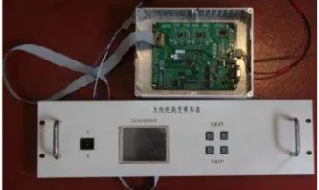
The RS-485 field bus has been designed and used in the universal controller in this research. In order to validate the RS-485 transmission protocol and interface circuits, the simulation training system is connected. But for that the whole missile simulation training system is complicated and relates to military affairs, this paper just gives the part of the simulation training system, wireless altitude meter unit. Figure 5 shows the photograph of the wireless altitude meter unit including the universal controller.As shown in Figure 5, the unit include the controller box and the control panel. The panel is composed with one power switch, one TFT LCD displayer and some tune buttons.
Figure 4. PCB board of the universal
controller Figure 5. Photogragh of the wireless altitudemeter
6.2. Tansmission Protocol Validation
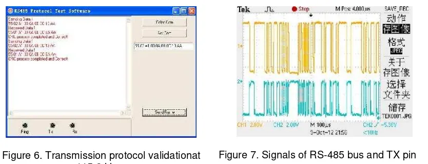
The protocol validation is carried out using the upper computer test software shown in Figure 6. The host computer connects the distributed universal controller on the bus. The address of the host is set 0x01. Run the test software, open the COM1, set the baud rate to be 115.2 kbps, and input the send frame as ‘0x55 0x02 0xA1 0x03 0x0A 0x0B 0x0C 0x13 0xAA’, and push button ‘Send Frame’. Then the host computer will setup communication with the slave controller. The controller addressed of 0x02 gets the frame and confirms the command byte0xA1, and then sends the received frame to the host, just after changing the address byte 0x02 to 0x01.
The communication process and result between host and slaves using upper computer test software based on transmission protocol at 115.2 kbps baud rate is presented in Figure 6. The communication result shows that the sent frame is ‘0x55 0x02 0xA1 0x03 0x0A 0x0B 0x0C 0x13 0xAA’, the received frame is ‘0x55 0x01 0xA1 0x03 0x0A 0x0B 0x0C 0xEA 0xAA’, and that CRC is passed. So the RS-485 transmission protocol is validated correct.
6.3. Interface Circuits Validation
To check the RS-485 interface circuits, using an oscillograph to scan the TX pin of the MAX483E ESA and the two bus lines, the signal of the TX pin and differential signal between A and B is given in Figure7. Channel 1 shows that the high voltage level of A and B exceeds 200 mV and the low voltage level is less than -200mV. The absolute value of the differential signal of A and B is less than 4V, which satisfies the RS-485 standard. Figure7 also shows that TX signal is accordant with the send state of the bus.
6.4. Stability Testing
Figure 6. Transmission protocol validationat 115.2 kbps
Figure 7. Signals of RS-485 bus and TX pin
7. Conclusion
The RS-485 field bush as been successfully designed and implied in the universal controller of the missile simulation training system. The experiment results indicate that the RS-485 interface circuits is perfect, the transmission protocol is fulfill the needs of the missile simulation training system, the efficient data transmission rates reaches 115.2 kbps, and has a good stability.The universal controller designed has some universal capability and can be used in other distributed system.
Acknowledgments
The authors would like to thank to Department of Aeronautical Ammunition Engineering of The First Aeronautical College of Air Force for the support given thoughout this research.
References
[1] Dietrich Birus, Thomas Rummel, Marko Fricke, Klaus Petry, Horst Demattio. Development of Quench
Detection System for W7-X.Fusion Engineering and Design. 2007; 82(5-14):1400-1405.
[2] Ying Zhang, Junjiang Chen, Wensheng Wang. Application of master-slave multi-communication
system in pilotless airborne mapping equipment. Proc. of SPIE 7133, Fifth SPIE International Symposium on Instrumentation Science and Technology. Shenyang. 2009: 71330U1-7.
[3] K Manoj, KV Ajit, A Srividya. Response-Time Modeling of Controller Area Network (CAN). Lecture
Notes in Computer Science. 2009; 5408(1): 163-174.
[4] İbrahim Özçelik, Hüseyin Ekiz. Building an interconnection between PROFIBUS and ATM networks.
Journal of Network and Computer Applications. 2007; 30(2):800-817.
[5] Hao Zhang, Yanan Li, Huiling Zhu. Development for Protocol Conversion Gateway of Profibus and
Modbus.Procedia Engineering. 2011; 15: 767-771.
[6] Qiumig Ma, Fuwen Sun, Yanhong Wang, Yanhui Xie and Hong Ding.A New Solution of Concurrent
Field Bus. 3rd IEEE International Conference on Innovative Computing Information and Control.
Dalian. 2008: 262-265.
[7] Yanhong Wang, QiumingMa, Fuwen Sun, Yanhui Xie, Hong Ding. Concurrent bus based on direct
sequence spread spectrum. IEEE International Conference on Information and Automation. Zhangjiajie. 2008: 900-904.
[8] AL Roginsky, KJ Christensen, S Polge. Efficient computation of packet CRC from partial CRCs with
application to the Cells-In-Frames protocol.Computer Communications. 1998; 21(7):654-661.
[9] Lin Cui, Seok Joo Koh. Partial CRC Checksum of SCTP for Error Control over Wireless Networks.
Wireless Personal Communications. 2009; 48(2): 247-260.
[10] T Mattes, F Schiller, A Mrwald, T Honold. Analysis of Nested CRC with Additional Net Data in
Communication.Lecture Notes in Computer Science. 2008; 5219(1): 126-138.
[11] Baicheva, S Dodunekov, P Kazakov. On the cyclic redundancy-check codes with 8-bit redundancy.
Computer Communications. 1998; 21(1): 1030-1033.