2351-9789 © 2015 The Authors. Published by Elsevier B.V. This is an open access article under the CC BY-NC-ND license (http://creativecommons.org/licenses/by-nc-nd/4.0/).
Peer review under responsibility of the organizing committee of the Industrial Engineering and Service Science 2015 (IESS 2015) doi: 10.1016/j.promfg.2015.11.052
Procedia Manufacturing 4 ( 2015 ) 359 – 372
ScienceDirect
Industrial Engineering and Service Science 2015, IESS 2015
Head and neck movement: simulation and kinematics analysis
Bernadus Kristyanto
a*, Brillianta Budi Nugraha
b, Anugrah Kusumo Pamosoaji
c, Kristanto
Agung Nugroho
da,b,c,d Faculty of Industrial Technology, Atma Jaya University Yogyakarta, Yogyakarta 55281, Indonesia.
Abstract
In Ergonomics, interaction system between human with some object or machine starts from the stimulation of the object to the head through the eyes. Therefore, the eyes position on the head when receiving the stimulation is very important. The eyes’ ability in receiving stimulation from the object depends on a person’s head and neck movement. Measuring the ability of the head and neck movement is very important, however explaining this matter to the students is complicated. In consequently, to make a simple way in explaining to the students, a head and neck anthropometry model or Head Mannequin design that can be moved in simulation of the visual design is needed. This research is aimed to assess the behavior and limitation movement of the human head and neck. A head model of mannequin is made and developed to make a simulation for ergonomic movement learning using Solid work software. The components of construction movement are analyzed by kinematic analysis using MATLAB to convince the simulation of human head movement. The results of the study show that head mannequin is able to simulate the human head movement. The kinematic models of head movement based on limitations are generated and the analysis is presented in the full paper.
© 2015 The Authors. Published by Elsevier B.V.
Peer-review under responsibility of the organizing committee of the Industrial Engineering and Service Science 2015 (IESS 2015).
Keywords:Ergonomics-Anthropometry, head and neck movement, solid work model, MATLAB, mannequin (robot)
* Corresponding author. Tel.: +0-000-000-0000 ; fax: +0-000-000-0000 .E-mail address: [email protected]
© 2015 The Authors. Published by Elsevier B.V. This is an open access article under the CC BY-NC-ND license (http://creativecommons.org/licenses/by-nc-nd/4.0/).
1.Introduction
Head mannequin prototype and the ability of movements are needed for learning system process. Firstly, in Ergonomics to understand about head movement system and limitation. Secondly, in mechatronics to understand the components of design and the control mechanism of movements. The strength and flexibility of the neck are important to design a mannequin that adopts a person’s behavior. However, to design the head and neck movement the mathematics model analysis should be done first. Those are kinematic analysis and dynamics analysis. From this analysis, the constrain of movement was obtained. In this research, the study of head and neck movement will not talk about the problems of head or neck injuries caused by spinal nerves but more about head and neck movements and its limitations. Analysis results from various head and neck movements with directions and angles that have limitation range will be applied as the basis of design for the movement simulation of the mannequin head prototype. The movement system will result on the movement mechanism design and the machine components that compose it. The mannequin head prototype and its movement ability are really needed for Ergonomic studies about the understanding of head movement system and its limitations and Mechatronic studies about component design and movement mechanism control for students of the Industrial Technology Faculty of University of Atma Jaya Yogyakarta. Apart from that, all mannequin prototypes that are able to do movements like human beings especially the mannequin head have never been made in Indonesia. Because of that, to support the technology development in robotics, this research has to be done. Coakwell MR, et.al. [1] did a research where the injured neck is made primary attention on pilots. The recent report shows hurt cervical spinal related to an action when increasing speed. From NATO and other organization's researches that are involved in technology, it is advised that the neck muscles need to be treated in order to be strong to reduce pain. The research method involves analysis of: biomechanics, ergonomics, orthopedics, neurology, neurosurgery, rehabilitative medicine, and aerospace medicine. Its descriptive objective is about muscle problems that are involved with head and neck movements. Research in head and neck movement analysis sector for various needs have been carried out by lots of people and is generally related with health. There are researches done because there is pain in the neck then it is advised to do certain movements to the head and neck to reduce the pain. But there are also researches that are related with the possibility of pain to the neck caused by certain movements of the head and neck so it is advised to do certain changes on how to move or give safe zones for its movement limitations.
Daniel A Sierra and John D Enderle [2], did a research about 3D dynamic model for complex movements of the head and neck. Here, the complex dynamic analysis is used because this head and neck movement is oriented with eye velocity.
To make a model of the head and neck and its movement with the help of software programs, the Head and Neck with its parts Anthropometry Data is needed. The use of anthropometry data and biomechanics model development in designing equipment or product is important for the effort of uniting human and equipment, especially in manufacturing.
2.Method
This research has two goals. The first is to find the constraints of movements based on kinematics analysis. These constrains are important as a basic of algorithm for controlling head movements. Second is to find the stability of head movement model.
2.1. Simulation model
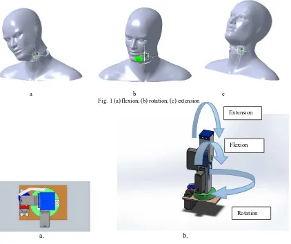
The three models of head movements were developed and investigated within their limitations. From the first research of Kristyanto, et.al [3] it was found that the range of movement (ROM) based on references was 144 20° for Rotation and 122 20° for Flexion or Extension. While research shows 140° for Rotation and 130° for Flexion or Extension. The total ROM for Rotation is greater than the total ROM for Flexion or Extension. Here an assumption has been made, that women and men are same because the result of measurements were quite similar. To perform
r
those movements the components of mechanism have been composed as follows in Fig. 1 for simulation. Fig. 2 shows the head movements at 3 directions.
2.2. Solidwork model
Here Solid work software has been used to develop the components for simulation as seen in Fig. 1. The model was built to be able to conduct movements like the head movements mentioned in Fig. 2. Based on those movements, there are 3 degrees of freedom (dof) involved in the system. The model is shown in Fig. 3.
a b c Fig. 1 (a) flexion; (b) rotation; (c) extension
a. b.
Fig. 2. Model 1 (a) top view; (b) 3D view
Extension
Flexion
Fig. 3. Model 2 (motor on center), 3 D view
3. Kinematics Model
3.1 Model 1
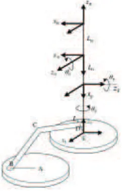
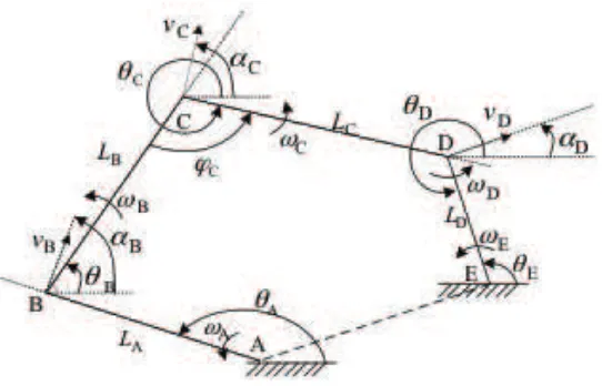
Two models have been analysis for kinematics. First model base on the actuator that use motor installed outside of main arm (main link) as see in Fig. 4, which diagram as seen in Fig. 5. The second model used actuator base with motor direct installed on the basis main arm as seen in Fig. 6.
Fig. 5. Cross section of actuator
T
E (structure base)The base actuator of the mannequin robot is depicted in Fig. 5. In this figure, there is active actuator A that is energized by a motor. Here, motor A performs an inclination angle TA; the angular velocity of actuator A is
symbolized as ZA. The other joints are passive ones: joint B performs angle under angular velocity ZB; joint C performs angle TC under angular velocity
Z
C; joint D performs angle TD under angular velocity ZD; and joint Eperforms angle TE under angular velocity ZE. The length of rigid links LA, LB, LC, and LD are constant. In addition, we define vB, vC, and vD as the velocities applied to the links LA, LB, LC, respectively. The inclination
angles of vB, vC, and vD with respect to global X-axis are symbolized as DB, DC, and DD, respectively.
Let B T
v be the tangential velocity of link LA with respect to rotation center A. According to Chakravarthy and Ghose [4], since A is static point, it is straightforward that
B AB
v
vTB sinD T . (1)
Since
D
BT
AS
, and A AB Z
T L
v , Eq. (1) becomes A
A
Z
L
vB . (2)
Let vTC be the tangential velocity of link LB with respect to rotation center of the passive joint B and be formulated
as
C B B B BC v
v L
vTC BZB sinD T sinD T . (3)
Substituting (2) to (3) yields
C BC B B
L V L
L Z D T D T
Z sin sin
B B
A A
B . (4)
We define D
T
v
as the tangential velocity of link LD with respect to rotation center of the passive joint C and beformulated as
D C C C CD v
v L
vT CZC sin D T sinD T
D . (5)
Substituting (4) and (5) and considering that ZC 0 yields
D C B BD C C B C
B
C v v
D
T
LZ
LZ
D
T
T
T
T
T
D
¸¹ · ¨
© § ¸¸
¹ · ¨¨
© §
¸ ¹ · ¨
© §
sin sin
2 cos 2
sin
2 B B A A . (6)
The tangential velocity D
T
v
can be formulated with respect to passive joint E as: D ED
v L
vTD DZE sinD T . (7)
Also, the motion of link LD leads to the formulation of point E’s motion with respect to point D as follows: B
D
v L
vTE DZD sinD T . (8)
Substitution of (7) to (6) and considering that
T
DT
ES
(which can be proven geometrically from Fig. 3) yieldsD D C D D C C C B C B
C v ¸v
¹ · ¨ © § ¸¸ ¹ · ¨¨ © § ¸ ¹ · ¨ © § ¸ ¹ · ¨ © § ¸¸ ¹ · ¨¨ © § ¸ ¹ · ¨ © § 2 cos 2 sin 2 cos 2
sin
D
T
T
T
T
T
T
D
T
T
B B A Asin D E2
1 Z Z D T Z
L L
L B B . (9)
From Fig. 5, it can be derived that the relationship between TE and TD is
D
E
S
T
T
. (10)Therefore, Eq. (10) can be rewritten as
D DD
v L
vT DZE sin SD T
D . (11)
Also, Eq. (8) can be reformulated as
D DD
v L
vTE DZD sinD T . (12)
Eqs. (11) and (12) lead to the following relationship:
D
E
Z
Z
. (13)Other constraints can be obtained from the fact that all of the links are static in length. Therefore, we have the following equations:
C B B B BC v
v cos
D
T
cosD
T
, (14) D C C C CD v
v cos
D
T
cosD
T
. (15)Also, we have
0cos
B vB B A
vU D T , (16)
which yields S T D ¸ ¹ · ¨ © § 2 1 k D
D , k ...,1,0,1,... (17)
Substitution of Eq. (7) to Eq. (17) gives us the following equation:
E D
Z
L
vD . (18)
Since
Z
EZ
D, and in consideration of Eq. (18), we can conclude that:D D E L VD Z
Z . (19)
Substituting Eq. (19) to Eq. (9) and using Eq. (4) gives:
C B CC B C
B
C ¸¸V
¹ · ¨¨ © § ¸ ¹ · ¨ © § ¸ ¹ · ¨ ©
§
D
T
T
T
T
D
T
sin 2 cos 2 sin 2 E D 2 cos 2 sin 2
1
T
T
D
T
CT
D LZ
D D C ¸¸ ¹ · ¨¨ © § ¸ ¹ · ¨ © § ¸ ¹ · ¨ © §
It can be proven from Figure 3 that
C B
T
T
S
M
C . (21)
Also, we substitute (2) to (14) and obtain
C B B BC L
V cos
D
T
AZ
AcosD
T
. (22)By substituting (21) and (22) to (20), we obtain the relationship between ZE and ZA as:
E
A
=
tan
C2
÷+
tan
(
C B)
÷
cos
(
B B)
L
A
1
+
2sin
C+
D2
÷
D÷
cos
C D
2
÷+
cos
(
D C)
tan
C
2
÷÷
L
D
. (23)
3.2 Model 2
F
L
F
z
F x
G z
G x
E
T
E z
E x
G L G
T
F
T
H z
H x
H L
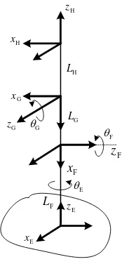
Fig. 6. Main link of model 2
Fig. 6 reveals the coordinates of the main links of the mannequin robot. Let JE, JF, and JG be defined as the angle between the angle between zE and , zF and zG, and, zG and zH, respectively. The transformation from frame E to frame F, F to G, and G to H can be respectively formulated as expressed by Krodkiewski [5], Xi and Xu [6], Zarkandi and Danieli [7]
F
» » » » ¼ º « « « « ¬ ª 1 0 0 0 0 0 0 0 0 0 E E E E E E E E E L s s c s s s c T J J T T J T T
, (24)
» » » » ¼ º « « « « ¬ ª 1 0 0 0 0 0 0 0 0 0 F F F F F F F F F L s s c s s s c T J J T T J T T
, (25)
» » » » ¼ º « « « « ¬ ª 1 0 0 0 0 0 0 0 0 0 G G G G G G G G G L s s c s s s c T J J T T J T T
, (26)
where the symbols s
T
andc
T
representsin
T
and cosT
, respectively. From (24) to (26), the transformation from frame E to H can be expressed as» » » » ¼ º « « « « ¬ ª » » » » » ¼ º « « « « « ¬ ª » » » » ¼ º « « « « ¬ ª 1 1 4,1 4,2 4,3 4,4
4 , 3 3 , 3 2 , 3 1 , 3 4 , 2 3 , 2 2 , 2 1 , 2 4 , 1 3 , 1 2 , 1 1 , 1 E E E H H H z y x T T T T T T T T T T T T T T T T z y x
, (27)
where G F E E G F
Ec c s s s s
c
T1,1 T T T T J J T (28a)
G F F Es s s
c
T1,2
T
T
J
J
(28b) c Ec Fs G s Es Es Fc Gs GT1,3 T T T T J J T J , (28c)
E E F F F E
Gc s s L s s
L
T1,4 T T J T J (28d)
G F E E G F
Es c c s s s
s
T2,1 T T T T J J T (28e)
G F F Es s s
s
T2,2
T
T
J
J
(28f) s Es Fs G c Es Es Fc Gs GT2,3 T T T T J J T J (28g)
E F F E
Gs s s L
L
T2,4
T
T
J
(28h)G F Es c
s
T3,1
J
T
T
(28i)G F F Ec s s
s
T3,2
J
T
J
J
(28j)G G F Es s s
s
T3,3
J
T
T
J
(28k)E F F E
Gs c s L
L
T3,4
J
T
J
(28l)0 3 , 4 2 , 4 1 ,
4 T T
T (28m) 1 4 , 4 T (28n)
3.3. Model Analysis
joint were:
T
A150
q
,T
B30
q
,T
C315
q
,T
D280
q
, andT
E100
q
. With angle of arm support wasq
85
C
M
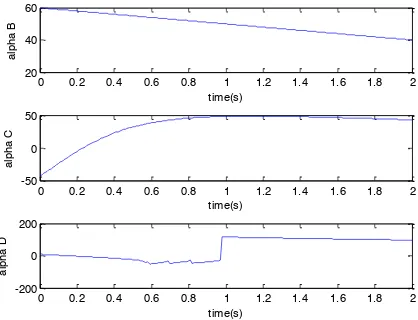
.The simulation results can be seen in Fig. 7 and Fig. 8. Simulation shows that there is no continuities problem at the joints A,B, and C. The problem was only found at joint D that as increasing degree about
50
q
,the discontinuity was occurred. The physical impact of this problem is that motor can not be program beyond50
q
caused of limitation of arm supported has constant angle ofM
C85
q
. Therefore this model 1 could not be used for this robot mannequin. Then Model 2 was used for this robot mannequin by using equation 30 for function transferring.Fig. 7. Simulation results of joint angle motions from model 1
Fig. 8. Simulation results of changing ranges of angle
D
B,D
C, andD
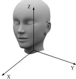
D at model 1For model 2 the coordinate system used was Cartesian which
x
E,
y
E,
z
E, as a center of motion and called as a BASE, then trajectory which are produced by end effector will be measured based on coordinate BASE.0 0.5 1 1.5 2
120 130 140 150
time(s)
th
e
ta
A
0 0.5 1 1.5 2
0 50 100 150
time(s)
th
e
ta
B
0 0.5 1 1.5 2
-50 0 50
time(s)
thet
a C
0 0.5 1 1.5 2
-150 -100 -50 0 50
time(s)
thet
a D
0 0.2 0.4 0.6 0.8 1 1.2 1.4 1.6 1.8 2
20 40 60
time(s)
al
pha B
0 0.2 0.4 0.6 0.8 1 1.2 1.4 1.6 1.8 2
-50 0 50
time(s)
al
pha C
0 0.2 0.4 0.6 0.8 1 1.2 1.4 1.6 1.8 2
-200 0 200
time(s)
al
X
Y Z
Fig. 9. Coordinate BASE system of neck mannequin robot
Simulation on kinematics model 2 will be carried out for 3 standard motions or movements of head. Nod motion when
Z
E0
,Z
F!
0
, andZ
G0
. And look up whenZ
E0
,Z
F0
, andZ
G0
. While left tilt motion whenZ
E0
,Z
F0
, andZ
G!
0
and right tilt whenZ
E0
,Z
F0
, andZ
G0
. Turn left motion when0
E
Z
,Z
F0
, andZ
G0
, and turn right whenZ
E!
0
,Z
F0
, andZ
G0
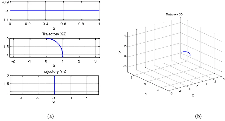
.In this simulation some assumption have been taken such as
L
EL
FL
G1
m
. And initial angle0
G F
E
T
T
T
rad. Simulation also was run for absolute angular velocityZ
10
q
/
sec
. Those all the results of simulation can be shown at Fig. 10, 11, 12, 13, and 14 as consecutive.(a) (b)
Fig. 10. Trajectory for left flexion (CW) for Model 2: (a) for planes X-Y, X-Z, and Y-Z ; (b) 3-D plane
-3 -2 -1 0 1 2
-0.8 -0.6 -0.4
-0.20
Trajectory X-Y
X
Y
-0.8 -0.6 -0.4 -0.2
1.9 2 2.1
Trajectory X-Z
X
Z
-0.8 -0.6 -0.4 -0.2 0
1.9 2 2.1
Trajectory Y-Z
Y
Z -3 -2 -1
0 1
2 3
-2 0 2 -2
0 2 4
Z
Trajectory 3D
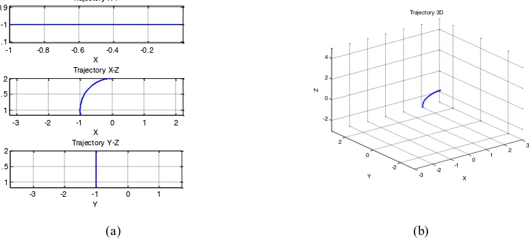
(a) (b)
Fig. 11. Trajectory for right flexion (CCW) for Model 2: (a) for planes X-Y, X-Z, and Y-Z; (b) 3-D plane
(a) (b)
Fig. 12. Trajectory for look down extension for Model 2: (a) for planes X-Y, X-Z, and Y-Z ; (b)3-D plane
-2 -1 0 1 2 3
-1 -0.5 0
Trajectory X-Y
X
Y
0 0.2 0.4 0.6 0.8 1
1.9 2 2.1
Trajectory X-Z
X
Z
-1 -0.8 -0.6 -0.4 -0.2 0
1.9 2 2.1
Trajectory Y-Z
Y
Z
0 0.2 0.4 0.6 0.8 1 -1.1
-1 -0.9
Trajectory X-Y
X
Y
-2 -1 0 1 2 3 1
1.5 2
Trajectory X-Z
X
Z
-3 -2 -1 0 1 1
1.5 2
Trajectory Y-Z
Y
Z
-3 -2 -1 0
1 2
3
-2 0 2 -2
0 2 4
Z
Trajectory 3D
X Y
-3 -2 -1 0
1 2
3
-2 0 2 -2
0 2 4
X Trajectory 3D
Y
(a) (b)
Fig. 13. Trajectory for look up extension of Model 2: (a) for planes X-Y, X-Z, and Y-Z ; (b) 3-D plane
(a) (b)
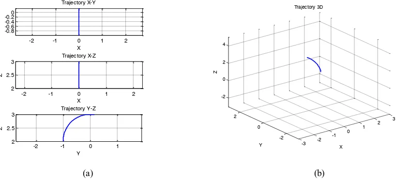
Fig. 14. Trajectory for left rotation of Model 2: (a) for planes X-Y, X-Z, and Y-Z; (b) 3-D plane
-1 -0.8 -0.6 -0.4 -0.2
-1.1 -1 -0.9
Trajectory X-Y
X
Y
-3 -2 -1 0 1 2
1 1.5 2
Trajectory X-Z
X
Z
-3 -2 -1 0 1
1 1.5 2
Trajectory Y-Z
Y
Z
-2 -1 0 1 2
-0.8 -0.6 -0.4 -0.20
Trajectory X-Y
X
Y
-2 -1 0 1 2
1 1.5 2
Trajectory X-Z
X
Z
-2 -1 0 1
1 1.5 2
Trajectory Y-Z
Y
Z
-3 -2 -1 0
1 2
3
-2 0 2 -2
0 2 4
X Trajectory 3D
Y
Z
-3 -2
-1 0
1 2
3
-2 0 2 -2
0 2 4
X Trajectory 3D
Y
(a) (b)
Fig. 15. Trajectory for right rotation of Model 2: (a) for planes X-Y, X-Z, and Y-Z , (b) 3-D plane
3.Conclusion
Through design process and analysis using MATLAB simulation can be concluded that mechanic design for head and neck movement that is flexible applied on model 2. Based on the kinematics simulation that have been carried out this mechanic design gave range of motion (ROM) its angle greater than mechanic design 1. Through this simulation also can be concluded that based on the kinematic analysis design model 2 more stable for given constant angular velocity.
Some researchers have been recommended for next futures such as:
a. Anthropometric characteristics mapping into DH parameters of neck mannequin robots. This researches need dynamics analysis
b. Inverse kinematics Exploration to produce the right algorithm control and proportional. c. Stability analysis based on dynamics
d. Control system design based kinematics and dynamics
Acknowledgements
The first author would like to acknowledge Ministry of Higher Education (DIKTI) for providing a scholarship to conduct this research.
References
[1] M.R. Coakwell , D.S. Poloswick , R. Moser Jr., High Risk Head and Neck Movements at High G and Intervention to Reduce Associated neck Injury, Aviat Space Environment Med.USA, 2004.
[2] D. A. Siera , J. D. Enderle, 3D Dynamic Modeling of The Head –Neck Complex For Fast Eye and Head Orientation Movements , Journal of Modeling and Simulation in Engineering, USA, 2011.
[3] B. Kristyanto, B. B. Nugraha, Assessing a Person’s Head and Neck Movement as The Design Basis of Mannequin’s Movement and Simulation, Indonesia Gov. DIKTI reasearch Grand, year1, 2014.
[4] A. Chakravarthy, D. Ghose, Obstacle Avoidance in A Dynamic Environment: A Collision Cone Approach, IEEE Transactions on Systems, Man, and Cybernetics – Part A 28 (5), 1998, 562-574.
[5] J.M. Krodkiewski, Dynamics of Mechanical Systems, The University of Melbourne, Department of Mechanical and Manufacturing Engineering, 2008.
-2 -1 0 1 2
-0.8 -0.6 -0.4
-0.20
Trajectory X-Y
X
Y
-2 -1 0 1 2
2 2.5 3
Trajectory X-Z
X
Z
-2 -1 0 1
2 2.5 3
Trajectory Y-Z
Y
Z
-3 -2
-1 0
1 2
3
-2 0 2 -2
0 2 4
X Trajectory 3D
Y
[6] Y. Li, Q. Xu, Kinematic Analysis of A 3-PRS Parallel Manipulator, Robotics and Computer-Integrated Manufacturing 23, 2007, 395-408.