1
Circuit Variables
Assessment Problems
AP 1.1 Use a product of ratios to convert two-thirds the speed of light from meters
per second to miles per second:
2
3
3
×
10
8m
1 s
·
100 cm
1 m
·
1 in
2.54 cm
·
1 ft
12 in
·
1 mile
5280 feet
=
124,274.24 miles
1 s
Now set up a proportion to determine how long it takes this signal to travel
1100 miles:
124,274.24 miles
1 s
=
1100 miles
x
s
Therefore,
x
=
1100
124,274.24
= 0.00885 = 8.85
×
10
−3s = 8.85 ms
AP 1.2 To solve this problem we use a product of ratios to change units from
dollars/year to dollars/millisecond. We begin by expressing $10 billion in
scientific notation:
$100 billion = $100
×
10
9Now we determine the number of milliseconds in one year, again using a
product of ratios:
1 year
365.25 days
·
1 day
24 hours
·
1 hour
60 mins
·
1 min
60 secs
·
1 sec
1000 ms
=
1 year
31.5576
×
10
9ms
Now we can convert from dollars/year to dollars/millisecond, again with a
product of ratios:
$100
×
10
91 year
·
1 year
31.5576
×
10
9ms
=
100
AP 1.3 Remember from Eq. (1.2), current is the time rate of change of charge, or
i
=
dqdtIn this problem, we are given the current and asked to find the total
charge. To do this, we must integrate Eq. (1.2) to find an expression for
charge in terms of current:
q(t) =
Z
t0
i(x)
dx
We are given the expression for current,
i, which can be substituted into the
above expression. To find the total charge, we let
t
→ ∞
in the integral. Thus
we have
AP 1.4 Recall from Eq. (1.2) that current is the time rate of change of charge, or
i
=
dqdt. In this problem we are given an expression for the charge, and asked to
find the maximum current. First we will find an expression for the current
using Eq. (1.2):
i
=
dq
Now that we have an expression for the current, we can find the maximum
value of the current by setting the first derivative of the current to zero and
solving for
t:
di
never equals 0 for a finite value of
t, the expression equals 0 only
when (1
−
αt) = 0. Thus,
t
= 1/α
will cause the current to be maximum. For
this value of
t, the current is
Remember in the problem statement,
α
= 0.03679. Using this value for
α,
i
=
1
0.03679
e
−1
∼
= 10 A
AP 1.5 Start by drawing a picture of the circuit described in the problem statement:
Also sketch the four figures from Fig. 1.6:
[a]
Now we have to match the voltage and current shown in the first figure
with the polarities shown in Fig. 1.6. Remember that 4A of current
entering Terminal 2 is the same as 4A of current leaving Terminal 1. We
get
(a)
v
=
−
20 V,
i
=
−
4 A; (b)
v
=
−
20 V,
i
= 4 A
(c)
v
= 20 V,
i
=
−
4 A;
(d)
v
= 20 V,
i
= 4 A
[b]
Using the reference system in Fig. 1.6(a) and the passive sign convention,
p
=
vi
= (
−
20)(
−
4) = 80 W. Since the power is greater than 0, the box is
absorbing power.
[c]
From the calculation in part (b), the box is absorbing 80 W.
AP 1.6
[a]
Applying the passive sign convention to the power equation using the
voltage and current polarities shown in Fig. 1.5,
p
=
vi. To find the time
at which the power is maximum, find the first derivative of the power
with respect to time, set the resulting expression equal to zero, and solve
for time:
p
= (80,000te
−500t)(15te
−500t) = 120
×
10
4t
2e
−1000tdp
dt
= 240
×
10
4te
−1000tTherefore,
240
×
10
4−
120
×
10
7t
= 0
Solving,
t
=
240
×
10
4120
×
10
7= 2
×
10
−3= 2 ms
[b]
The maximum power occurs at 2 ms, so find the value of the power at 2
ms:
p(0.002) = 120
×
10
4(0.002)
2e
−2= 649.6 mW
[c]
From Eq. (1.3), we know that power is the time rate of change of energy,
or
p
=
dw/dt. If we know the power, we can find the energy by
integrating Eq. (1.3). To find the total energy, the upper limit of the
integral is infinity:
wtotal
=
Z
∞0
120
×
10
4
x
2e
−1000xdx
=
120
×
10
4(
−
1000)
3e
−1000x
[(
−
1000)
2x
2−
2(
−
1000)x
+ 2)
∞
0
= 0
−
120
×
10
4
(
−
1000)
3e
0
(0
−
0 + 2) = 2.4 mJ
AP 1.7 At the Oregon end of the line the current is leaving the upper terminal, and
thus entering the lower terminal where the polarity marking of the voltage is
negative. Thus, using the passive sign convention,
p
=
−
vi. Substituting the
values of voltage and current given in the figure,
p
=
−
(800
×
10
3)(1.8
×
10
3) =
−
1440
×
10
6=
−
1440 MW
Chapter Problems
P 1.1
(260
×
10
6
)(540)
10
9= 104.4 gigawatt-hours
P 1.2
(480)(320) pixels
1 frame
·
P 1.3
[a]
20,000 photos
(11)(15)(1) mm
3=
x
photos
1 mm
3x
=
(20,000)(1)
(11)(15)(1)
= 121 photos
[b]
16
×
2
(11)(15)(1)
= 832,963 bytes
P 1.4
(4 cond.)
·
(845 mi)
·
5280 ft
P 1.5
Volume = area
×
thickness
Convert values to millimeters, noting that 10 m
2= 10
6mm
210
6= (10
×
10
6)(thickness)
⇒
thickness =
10
610
×
10
6= 0.10 mm
P 1.6
[a]
We can set up a ratio to determine how long it takes the bamboo to grow
10
µm First, recall that 1 mm = 10
3µm. Let’s also express the rate of
growth of bamboo using the units mm/s instead of mm/day. Use a
product of ratios to perform this conversion:
250 mm
[b]
1 cell length
3.456 s
·
3600 s
1 hr
·
(24)(7) hr
1 week
= 175,000 cell lengths/week
P 1.7
[a]
First we use Eq. (1.2) to relate current and charge:
i
=
dq
dt
= 0.125e
−2500tTherefore,
dq
= 0.125e
−2500tdt
To find the charge, we can integrate both sides of the last equation. Note
that we substitute
x
for
q
on the left side of the integral, and
y
for
t
on
the right side of the integral:
Z
q(t)We solve the integral and make the substitutions for the limits of the
integral:
P 1.8
First we use Eq. (1.2) to relate current and charge:
i
=
dq
dt
= 20 cos 5000t
Therefore,
dq
= 20 cos 5000t dt
To find the charge, we can integrate both sides of the last equation. Note that
we substitute
x
for
q
on the left side of the integral, and
y
for
t
on the right
side of the integral:
Z
q(t)q(0)
dx
= 20
Z
t0
cos 5000y dy
We solve the integral and make the substitutions for the limits of the integral,
remembering that sin 0 = 0:
q(t)
−
q(0) = 20
sin 5000y
5000
sin 5000t
−
20
5000
sin 5000(0) =
20
5000
sin 5000t
But
q(0) = 0 by hypothesis, i.e., the current passes through its maximum
value at
t
= 0, so
q(t) = 4
×
10
−3P 1.9
[a]
First we use Eq. (1.2) to relate current and charge:
i
=
dq
dt
= 40te
−500tTherefore,
dq
= 40te
−500tdt
To find the charge, we can integrate both sides of the last equation. Note
that we substitute
x
for
q
on the left side of the integral, and
y
for
t
on
the right side of the integral:
Z
q(t)q(0)
dx
= 40
Z
t0
ye
−500ydy
We solve the integral and make the substitutions for the limits of the
integral:
q(t)
−
q(0) = 40
e
−500y(
−
500)
2(
−
500y
−
1)
t0
= 160
×
10
−6e
−500t(
−
500t
−
1) + 160
×
10
−6= 160
×
10
−6(1
−
500te
−500t−
e
−500t)
But
q(0) = 0 by hypothesis, so
q(t) = 160(1
−
500te
−500t−
e
−500t)
µC
[b]
q(0.001) = (160)[1
−
500(0.001)e
−500(0.001)−
e
−500(0.001)= 14.4
µC.
P 1.10
n
=
35
×
10
−6
C/s
1.6022
×
10
−19C/elec
= 2.18
×
10
14
elec/s
P 1.11
w
=
qV
= (1.6022
×
10
−19)(6) = 9.61
×
10
−19= 0.961 aJ
P 1.12
[a]
p
=
vi
= (40)(
−
10) =
−
400 W
Power is being delivered by the box.
[b]
Entering
[c]
Gaining
[c]
Losing
P 1.14
Assume we are standing at box A looking toward box B. Use the passive sign
convention to get
p
=
vi, since the current
i
is flowing into the + terminal of
the voltage
v. Now we just substitute the values for
v
and
i
into the equation
for power. Remember that if the power is positive, B is absorbing power, so
the power must be flowing from A to B. If the power is negative, B is
generating power so the power must be flowing from B to A.
[a]
p
= (30)(6) = 180 W
180 W from A to B
[b]
p
= (
−
20)(
−
8) = 160 W
160 W from A to B
[c]
p
= (
−
60)(4) =
−
240 W
240 W from B to A
[d]
p
= (40)(
−
9) =
−
360 W
360 W from B to A
P 1.15
[a]
In Car A, the current
i
is in the direction of the voltage drop across the 12
V battery(the current
i
flows into the + terminal of the battery of Car
A). Therefore using the passive sign convention,
p
=
vi
= (30)(12) = 360 W.
Since the power is positive, the battery in Car A is absorbing power, so
Car A must have the ”dead” battery.
[b]
w(t) =
Z
t0
p dx;
1 min = 60 s
w(60) =
Z
600
360
dx
w
= 360(60
−
0) = 360(60) = 21,600 J = 21.6 kJ
P 1.16
p
=
vi;
w
=
Z
t 0p dx
P 1.21
[a]
p
=
vi
When
t
=
∞
all the upper limits evaluate to zero, hence
w
=
60
[1,024,000t
+ 1024]
−
2000e
−2000t[512,000t
2+ 1024t
+ 0.512]
1024e
−2000xWhen
t
→ ∞
all the upper limits evaluate to zero, hence
w
=
(512,000)(2)
8
×
10
9+
1024
4
×
10
6+
0.512
2000
w
= 128
×
10
−6+ 256
×
10
−6+ 256
×
10
−6= 640
µJ.
P 1.23
[a]
We can find the time at which the power is a maximum by writing an
expression for
p(t) =
v
(t)i(t), taking the first derivative of
p(t)
and setting it to zero, then solving for
t. The calculations are shown below:
p
= 0
t <
0,
p
= 0
t >
40 s
p
=
vi
=
t(1
−
0.025t)(4
−
0.2t) = 4t
−
0.3t
2+ 0.005t
3W
0
≤
t
≤
40 s
dp
dt
= 4
−
0.6t
+ 0.015t
2
= 0.015(t
2−
40t
+ 266.67)
dp
dt
= 0
when
t
2
−
40t
+ 266.67 = 0
t1
= 8.453 s;
t2
= 31.547 s
(using the polynomial solver on your calculator)
p(t1
)
= 4(8.453)
−
0.3(8.453)
2+ 0.005(8.453)
3= 15.396 W
p(t2
)
= 4(31.547)
−
0.3(31.547)
2+ 0.005(31.547)
3=
−
15.396 W
Therefore, maximum power is being delivered at
t
= 8.453 s.
[b]
The maximum power was calculated in part (a) to determine the time at
which the power is maximum:
pmax
= 15.396 W (delivered)
[c]
As we saw in part (a), the other “maximum” power is actually a
minimum, or the maximum negative power. As we calculated in part (a),
maximum power is being extracted at
t
= 31.547 s.
[d]
This maximum extracted power was calculated in part (a) to determine
the time at which power is maximum:
pmax
= 15.396 W (extracted)
[e]
w
=
Z
t 0pdx
=
Z
t0
(4x
−
0.3x
2
+ 0.005x
3)dx
= 2t
2−
0.1t
3+ 0.00125t
4w(0)
=
0 J
w(30)
= 112.5 J
w(10)
=
112.5 J
w(40)
= 0 J
w(20)
=
200 J
P 1.24
[a]
v(10 ms) = 400e
−1sin 2 = 133.8 V
i(10 ms) = 5e
−1[b]
p
=
vi
= 2000e
−200tcos 400t dt
= 1000
e
Therefore,
pmax
= 1000 W
[b]
pmax(extracting) = 1000 W
[c]
pavg
=
1
2.5
×
10
−3Z
2.5×10⁻³⁰
1000 sin(1600πt)
dt
=
4
×
10
512,000 s
≤
t
≤
16,000 s:
i
=
64
−
4
×
10
−3t
p
=
512
−
16
×
10
−3t
−
10
−6t
2w2
=
Z
16,00012,000
(512
−
16
×
10
−3t
−
10
−6t
2)
dt
=
(2048
−
896
−
789.33)10
3= 362.667 kJ
wT
=
w1
+
w2
= 2256 + 362.667 = 2618.667 kJ
P 1.27
[a]
0 s
≤
t <
10 ms:
v
= 8 V;
i
= 25t
A;
p
= 200t
W
10 ms
< t
≤
30 ms:
v
=
−
8 V;
i
= 0.5
−
25t
A;
p
= 200t
−
4 W
30 ms
≤
t <
40 ms:
v
= 0 V;
i
=
−
250 mA;
p
= 0 W
40 ms
< t
≤
60 ms:
v
= 8 V;
i
= 25t
−
1.25 A;
p
= 200t
−
10 W
t >
60 ms:
v
= 0 V;
i
= 250 mA;
p
= 0 W
[b]
Calculate the area under the curve from zero up to the desired time:
w(0.01)
=
12(2)(0.01) = 10 mJ
w(0.03)
=
w(0.01)
−
12
(2)(0.01) +
1P 1.28
[a]
[b]
i(t) =
10 + 0.5
×
10
−3t
mA, 0
≤
t
≤
10 ks
i(t) =
15 mA,
10 ks
≤
t
≤
20 ks
i(t) =
25
−
0.5
×
10
−3t
mA, 20 ks
≤
t
≤
30 ks
i(t) =
0,
t >
30 ks
p
=
vi
= 120i
so
[c]
To find the energy, calculate the area under the plot of the power:
w(10 ks) =
1
2
(0.6)(10,000) + (1.2)(10,000) = 15 kJ
w(20 ks) =
w(10 ks) + (1.8)(10,000) = 33 kJ
w(10 ks) =
w(20 ks) +
1
2
(0.6)(10,000) + (1.2)(10,000) = 48 kJ
P 1.29
We use the passive sign convention to determine whether the power equation
is
p
=
vi
or
p
=
−
vi
and substitute into the power equation the values for
v
and
i, as shown below:
pa
=
−
vaia
=
−
(40)(
−
4
×
10
−3) = 160 mW
pb
=
vbib
= (
−
24)(
−
4
×
10
−3) = 96 mW
pc
=
−
vcic
=
−
(
−
16)(4
×
10
−3) = 64 mW
pd
=
−
vdid
=
−
(
−
80)(
−
1.5
×
10
−3) =
−
120 mW
pe
=
veie
= (40)(2.5
×
10
−3) = 100 mW
pf
=
vfif
= (120)(
−
2.5
×
10
−3) =
−
300 mW
Remember that if the power is positive, the circuit element is absorbing
power, whereas is the power is negative, the circuit element is developing
power. We can add the positive powers together and the negative powers
together — if the power balances, these power sums should be equal:
X
Pdev
= 120 + 300 = 420 mW;
X
Pabs
= 160 + 96 + 64 + 100 = 420 mW
Thus, the power balances and the total power absorbed in the circuit is 420
mW.
P 1.30
pa
=
−
vaia
=
−
(
−
3000)(
−
250
×
10
−6) =
−
0.75 W
pb
=
−
vbib
=
−
(4000)(
−
400
×
10
−6) = 1.6 W
pc
=
−
vcic
=
−
(1000)(400
×
10
−6) =
−
0.4 W
pd
=
vdid
= (1000)(150
×
10
−6) = 0.15 W
pe
=
veie
= (
−
4000)(200
×
10
−6) =
−
0.8 W
pf
=
vfif
= (4000)(50
×
10
−6) = 0.2 W
Therefore,
X
Pabs
= 1.6 + 0.15 + 0.2 = 1.95 W
X
Pdel
= 0.75 + 0.4 + 0.8 = 1.95 W =
X
Pabs
P 1.31
[a]
From the diagram and the table we have
pa
=
−
vaia
=
−
(46.16)(6) =
−
276.96 W
pb
=
vbib
= (14.16)(4.72) = 66.8352 W
pc
=
vcic
= (
−
32)(
−
6.4) = 204.8 W
pd
=
−
vdid
=
−
(22)(1.28) =
−
28.16 W
pe
=
veie
= (
−
33.6)(
−
1.68) = 56.448 W
pf
=
vf
if
= (66)(0.4) = 26.4 W
pg
=
vg
ig
= (2.56)(1.28) = 3.2768 W
ph
=
−
vhih
=
−
(
−
0.4)(0.4) = 0.16 W
X
Pdel
= 276.96 + 28.16 = 305.12 W
X
Pabs
= 66.8352 + 204.8 + 56.448 + 26.4 + 3.2768 + 0.16 = 357.92 W
Therefore,
X
Pdel
6
=
X
Pabs
and the subordinate engineer is correct.
[b]
The difference between the power delivered to the circuit and the power
absorbed by the circuit is
−
305.12 + 357.92 = 52.8 W
One-half of this difference is 26.4 W, so it is likely that
pf
is in error.
Either the voltage or the current probably has the wrong sign. (In
Chapter 2, we will discover that using KCL at the node connecting
components f and h, the current
if
should be
−
0.4 A, not 0.4 A!) If the
sign of
pf
is changed from negative to positive, we can recalculate the
power delivered and the power absorbed as follows:
X
Pdel
= 276.96 + 28.16 + 26.4 = 331.52 W
X
Pabs
= 66.8352 + 204.8 + 56.448 + 3.2768 + 0.16 = 331.52 W
Now the power delivered equals the power absorbed and the power
balances for the circuit.
P 1.32
[a]
Remember that if the circuit element is absorbing power, the power is
positive, whereas if the circuit element is supplying power, the power is
negative. We can add the positive powers together and the negative
powers together — if the power balances, these power sums should be
equal:
X
Psup
= 600 + 50 + 600 + 1250 = 2500 W;
X
Pabs
= 400 + 100 + 2000 = 2500 W
Thus, the power balances.
ia
=
−
pa
/va
=
−
(
−
600)/(400) = 1.5 A
ib
=
pb/vb
= (
−
50)/(
−
100) = 0.5 A
ic
=
pc/vc
= (400)/(200) = 2.0 A
id
=
pd/vd
= (
−
600)/(300) =
−
2.0 A
ie
=
pe/ve
= (100)/(
−
200) =
−
0.5 A
if
=
−
pf
/vf
=
−
(2000)/(500) =
−
4.0 A
ig
=
pg
/vg
= (
−
1250)/(
−
500) = 2.5 A
P 1.33
[a]
If the power balances, the sum of the power values should be zero:
ptotal
= 0.175 + 0.375 + 0.150
−
0.320 + 0.160 + 0.120
−
0.660 = 0
Thus, the power balances.
[b]
When the power is positive, the element is absorbing power. Since
elements a, b, c, e, and f have positive power, these elements are
absorbing power.
[c]
The voltage can be calculated using
v
=
p/i
or
v
=
−
p/i, with proper
application of the passive sign convention:
va
=
pa/ia
= (0.175)/(0.025) = 7 V
vb
=
pb/ib
= (0.375)/(0.075) = 5 V
vc
=
−
pc/ic
=
−
(0.150)/(
−
0.05) = 3 V
vd
=
pd/id
= (
−
0.320)/(0.04) =
−
8 V
ve
=
−
pe/ie
=
−
(0.160)/(0.02) =
−
8 V
vf
=
pf
/if
= (0.120)/(
−
0.03) =
−
4 V
vg
=
pg
/ig
= (
−
0.66)/(0.055) =
−
12 V
P 1.34
pa
=
vaia
= (120)(
−
10) =
−
1200 W
pb
=
−
vbib
=
−
(120)(9) =
−
1080 W
pc
=
vcic
= (10)(10) = 100 W
pd
=
−
vdid
=
−
(10)(
−
1) = 10 W
pe
=
veie
= (
−
10)(
−
9) = 90 W
pf
=
−
vfif
=
−
(
−
100)(5) = 500 W
pg
=
vgig
= (120)(4) = 480 W
ph
=
vhih
= (
−
220)(
−
5) = 1100 W
X
X
Pabs
= 100 + 10 + 90 + 500 + 480 + 1100 = 2280 W
Therefore,
X
Pdel
=
X
Pabs
= 2280 W
Thus, the interconnection now satisfies the power check.
P 1.35
[a]
The revised circuit model is shown below:
[b]
The expression for the total power in this circuit is
vaia
−
vbib
−
vfif
+
vgig
+
vhih
= (120)(
−
10)
−
(120)(10)
−
(
−
120)(3) + 120ig
+ (
−
240)(
−
7) = 0
Therefore,
120ig
= 1200 + 1200
−
360
−
1680 = 360
so
ig
=
360
120
= 3 A
2
Circuit Elements
a
Assessment Problems
AP 2.1
[a] Note that the current
ib
is in the same circuit branch as the 8 A current
source; however,
ib
is defined in the opposite direction of the current
source. Therefore,
ib
=
−
8 A
Next, note that the dependent voltage source and the independent
voltage source are in parallel with the same polarity. Therefore, their
voltages are equal, and
vg
=
ib
4
=
−
8
4
=
−
2 V
[b] To find the power associated with the 8 A source, we need to find the
voltage drop across the source,
v
i. Note that the two independent sources
are in parallel, and that the voltages
vg
and
v1
have the same polarities,
so these voltages are equal:
v
i=
v
g=
−
2 V
Using the passive sign convention,
p
s= (8 A)(v
i) = (8 A)(
−
2 V) =
−
16 W
AP 2.2
[a] Note from the circuit that
v
x=
−
25 V. To find
α
note that the two
current sources are in the same branch of the circuit but their currents
flow in opposite directions. Therefore
αv
x=
−
15 A
Solve the above equation for
α
and substitute for
v
x,
α
=
−
15 A
v
x=
−
15 A
−
25 V
= 0.6 A/V
[b] To find the power associated with the voltage source we need to know the
current,
i
v. Note that this current is in the same branch of the circuit as
the dependent current source and these two currents flow in the same
direction. Therefore, the current
i
vis the same as the current of the
dependent source:
i
v=
αv
x= (0.6)(
−
25) =
−
15 A
Using the passive sign convention,
p
s=
−
(i
v)(25 V) =
−
(
−
15 A)(25 V) = 375 W.
Thus the voltage source dissipates 375 W.
AP 2.3
[a] The resistor and the voltage source are in parallel and the resistor voltage
and the voltage source have the same polarities. Therefore these two
voltages are the same:
Note from the circuit that the current through the resistor is
i
g= 5 mA.
Use Ohm’s law to calculate the value of the resistor:
R
=
v
Ri
g=
1 kV
5 mA
= 200 kΩ
Using the passive sign convention to calculate the power in the resistor,
p
R= (v
R)(i
g) = (1 kV)(5 mA) = 5 W
The resistor is dissipating 5 W of power.
[b] Note from part (a) the
v
R=
v
gand
i
R=
i
g. The power delivered by the
source is thus
psource
=
−
v
gi
gso
v
g=
−
psource
i
g=
−
−
3 W
75 mA
= 40 V
Since we now have the value of both the voltage and the current for the
resistor, we can use Ohm’s law to calculate the resistor value:
R
=
v
gi
g=
40 V
75 mA
= 533.33 Ω
The power absorbed by the resistor must equal the power generated by
the source. Thus,
p
R=
−
psource
=
−
(
−
3 W) = 3 W
[c] Again, note the
i
R=
i
g. The power dissipated by the resistor can be
determined from the resistor’s current:
p
R=
R(i
R)
2=
R(i
g)
2Solving for
i
g,
i
2g=
p
rR
=
480 mW
300 Ω
= 0.0016
so
i
g=
√
0.0016 = 0.04 A = 40 mA
Then, since
v
R=
v
gv
R=
Ri
R=
Ri
g= (300 Ω)(40 mA) = 12 V
so
v
g= 12 V
AP 2.4
[a] Note from the circuit that the current through the conductance
G
is
i
g,
conductance are in the same branch of the circuit so must have the same
current. The voltage drop across the current source is
v
g, positive at the
top, because the current source and the conductance are also in parallel
so must have the same voltage. From a version of Ohm’s law,
v
g=
i
gG
=
0.5 A
50 mS
= 10 V
Now that we know the voltage drop across the current source, we can
find the power delivered by this source:
psource
=
−
v
gi
g=
−
(10)(0.5) =
−
5 W
Thus the current source delivers 5 W to the circuit.
[b] We can find the value of the conductance using the power, and the value
of the current using Ohm’s law and the conductance value:
p
g=
Gv
g2so
G
=
p
gv
2g
=
9
15
2= 0.04 S = 40 mS
i
g=
Gv
g= (40 mS)(15 V) = 0.6 A
[c] We can find the voltage from the power and the conductance, and then
use the voltage value in Ohm’s law to find the current:
p
g=
Gv
g2so
v
g2=
p
gG
=
8 W
200
µS
= 40,000
Thus
v
g=
q
40,000 = 200 V
i
g=
Gv
g= (200
µS)(200 V) = 0.04 A = 40 mA
AP 2.5
[a]
Redraw the circuit with all of the voltages and currents labeled for every
circuit element.
Write a KVL equation clockwise around the circuit, starting below the
voltage source:
−
24 V +
v2
+
v5
−
v1
= 0
Next, use Ohm’s law to calculate the three unknown voltages from the
three currents:
A KCL equation at the upper right node gives
i2
=
i5
; a KCL equation at
the bottom right node gives
i5
=
−
i1; a KCL equation at the upper left
node gives
i
s=
−
i2. Now replace the currents
i1
and
i2
in the Ohm’s law
equations with
i5:
v2
= 3i2
= 3i5;
v5
= 7i5;
v1
= 2i1
=
−
2i5
Now substitute these expressions for the three voltages into the first
equation:
24 =
v2
+
v5
−
v1
= 3i5
+ 7i5
−
(
−
2i5) = 12i5
Therefore
i5
= 24/12 = 2 A
[b]
v1
=
−
2i5
=
−
2(2) =
−
4 V
[c]
v2
= 3i5
= 3(2) = 6 V
[d]
v5
= 7i5
= 7(2) = 14 V
[e]
A KCL equation at the lower left node gives
i
s=
i1. Since
i1
=
−
i5,
i
s=
−
2 A. We can now compute the power associated with the voltage
source:
p24
= (24)i
s= (24)(
−
2) =
−
48 W
Therefore 24 V source is delivering 48 W.
AP 2.6 Redraw the circuit labeling all voltages and currents:
We can find the value of the unknown resistor if we can find the value of its
voltage and its current. To start, write a KVL equation clockwise around the
right loop, starting below the 24 Ω resistor:
−
120 V +
v3
= 0
Use Ohm’s law to calculate the voltage across the 8 Ω resistor in terms of its
current:
v3
= 8i3
Substitute the expression for
v3
into the first equation:
−
120 V + 8i3
= 0
so
i3
=
120
Also use Ohm’s law to calculate the value of the current through the 24 Ω
resistor:
i2
=
120 V
24 Ω
= 5 A
Now write a KCL equation at the top middle node, summing the currents
leaving:
−
i1
+
i2
+
i3
= 0
so
i1
=
i2
+
i3
= 5 + 15 = 20 A
Write a KVL equation clockwise around the left loop, starting below the
voltage source:
−
200 V +
v1
+ 120 V = 0
so
v1
= 200
−
120 = 80 V
Now that we know the values of both the voltage and the current for the
unknown resistor, we can use Ohm’s law to calculate the resistance:
R =
v1
i1
=
80
20
= 4 Ω
AP 2.7
[a]
Plotting a graph of
v
tversus
i
tgives
Note that when
i
t= 0,
v
t= 25 V; therefore the voltage source must be 25
V. Since the plot is a straight line, its slope can be used to calculate the
value of resistance:
R
=
∆v
∆i
=
25
−
0
0.25
−
0
=
25
0.25
= 100 Ω
[b]
Draw the circuit model from part (a) and attach a 25 Ω resistor:
To find the power delivered to the 25 Ω resistor we must calculate the
current through the 25 Ω resistor. Do this by first using KCL to recognize
that the current in each of the components is
i
t, flowing in a clockwise
direction. Write a KVL equation in the clockwise direction, starting
below the voltage source, and using Ohm’s law to express the voltage
drop across the resistors in the direction of the current
i
tflowing through
the resistors:
−
25 V + 100i
t+ 25i
t= 0
so
125i
t= 25
so
i
t=
25
125
= 0.2 A
Thus, the power delivered to the 25 Ω resistor is
p25
= (25)i
2t= (25)(0.2)
2= 1 W.
AP 2.8
[a]
From the graph in Assessment Problem 2.7(a), we see that when
v
t= 0,
i
t= 0.25 A. Therefore the current source must be 0.25 A. Since the plot
is a straight line, its slope can be used to calculate the value of resistance:
R
=
∆v
∆i
=
25
−
0
0.25
−
0
=
25
0.25
= 100 Ω
A circuit model having the same
v
−
i
characteristic is a 0.25 A current
source in parallel with a 100Ω resistor, as shown below:
[b]
Draw the circuit model from part (a) and attach a 25 Ω resistor:
Note that by writing a KVL equation around the right loop we see that
the voltage drop across both resistors is
v
t. Write a KCL equation at the
to specify the currents through the resistors in terms of the voltage drop
across the resistors and the value of the resistors.
−
0.25 +
v
t100
+
v
t25
= 0,
so
5v
t= 25,
thus
v
t= 5 V
p25
=
v
2
t
25
= 1 W.
AP 2.9 First note that we know the current through all elements in the circuit except
the 6 kΩ resistor (the current in the three elements to the left of the 6 kΩ
resistor is
i1; the current in the three elements to the right of the 6 kΩ resistor
is 30i1). To find the current in the 6 kΩ resistor, write a KCL equation at the
top node:
i1
+ 30i1
=
i6k
= 31i1
We can then use Ohm’s law to find the voltages across each resistor in terms
of
i1. The results are shown in the figure below:
[a]
To find
i1, write a KVL equation around the left-hand loop, summing
voltages in a clockwise direction starting below the 5V source:
−
5 V + 54,000i1
−
1 V + 186,000i1
= 0
Solving for
i1
54,000i1
+ 186,000i1
= 6 V
so
240,000i1
= 6 V
Thus,
i1
=
6
240,000
= 25
µA
[b]
Now that we have the value of
i1, we can calculate the voltage for each
component except the dependent source. Then we can write a KVL
equation for the right-hand loop to find the voltage
v
of the dependent
source. Sum the voltages in the clockwise direction, starting to the left of
the dependent source:
Thus,
v
= 240,000i1
−
8 V = 240,000(25
×
10
−6)
−
8 V = 6 V
−
8 V =
−
2 V
We now know the values of voltage and current for every circuit element.
Let’s construct a power table:
Element
Current
Voltage
Power
Power
(µA)
(V)
Equation
(µW)
5 V
25
5
p
=
−
vi
−
125
54 kΩ
25
1.35
p
=
Ri
233.75
1 V
25
1
p
=
−
vi
−
25
6 kΩ
775
4.65
p
=
Ri
23603.75
Dep. source
750
−
2
p
=
−
vi
1500
1.8 kΩ
750
1.35
p
=
Ri
21012.5
8 V
750
8
p
=
−
vi
−
6000
[c]
The total power generated in the circuit is the sum of the negative power
values in the power table:
−
125
µW +
−
25
µW +
−
6000
µW =
−
6150
µW
Thus, the total power generated in the circuit is 6150
µW.
[d]
The total power absorbed in the circuit is the sum of the positive power
values in the power table:
33.75
µW + 3603.75
µW + 1500
µW + 1012.5
µW = 6150
µW
Thus, the total power absorbed in the circuit is 6150
µW.
AP 2.10 Given that
i
φ= 2 A, we know the current in the dependent source is
2i
φ= 4 A. We can write a KCL equation at the left node to find the current in
the 10 Ω resistor. Summing the currents leaving the node,
[a]
To find
v
s, write a KVL equation, summing the voltages counter-clockwise
around the lower right loop. Start below the voltage source.
−
v
s+ (1 A)(10 Ω) + (2 A)(30 Ω) = 0
so
v
s= 10 V + 60 V = 70 V
[b]
The current in the voltage source can be found by writing a KCL equation
at the right-hand node. Sum the currents leaving the node
−
4 A + 1 A +
i
v= 0
so
i
v= 4 A
−
1 A = 3 A
The current in the voltage source is 3 A, flowing top to bottom. The
power associated with this source is
p
=
vi
= (70 V)(3 A) = 210 W
Thus, 210 W are absorbed by the voltage source.
[c]
The voltage drop across the independent current source can be found by
writing a KVL equation around the left loop in a clockwise direction:
−
v5
A+ (2 A)(30 Ω) = 0
so
v5
A= 60 V
The power associated with this source is
p
=
−
v5
Ai
=
−
(60 V)(5 A) =
−
300 W
This source thus delivers 300 W of power to the circuit.
[d]
The voltage across the controlled current source can be found by writing a
KVL equation around the upper right loop in a clockwise direction:
+v4
A+ (10 Ω)(1 A) = 0
so
v4
A=
−
10 V
The power associated with this source is
p
=
v4
Ai
= (
−
10 V)(4 A) =
−
40 W
This source thus delivers 40 W of power to the circuit.
[e]
The total power dissipated by the resistors is given by
Problems
P 2.1
[a]
Yes, independent voltage sources can carry the 5 A current required by the
connection; independent current source can support any voltage required
by the connection, in this case 5 V, positive at the bottom.
[b]
20 V source:
absorbing
15 V source:
developing (delivering)
5 A source:
developing (delivering)
[c]
P20V
=
(20)(5) = 100 W (abs)
P15V
=
−
(15)(5) =
−
75 W (dev/del)
P5A
=
−
(5)(5) =
−
25 W
(dev/del)
X
Pabs
=
X
Pdel
= 100 W
[d]
The interconnection is valid, but in this circuit the voltage drop across the
5 A current source is 35 V, positive at the top; 20 V source is developing
(delivering), the 15 V source is developing (delivering), and the 5 A
source is absorbing:
P20V
=
−
(20)(5) =
−
100 W (dev/del)
P15V
=
−
(15)(5) =
−
75 W (dev/del)
P5A
= (35)(5) = 175 W
(abs)
X
Pabs
=
X
Pdel
= 175 W
P50V
=
(50)(5) = 250 W (abs)
P10V
=
(10)(5) = 50 W
(abs)
P40V
=
−
(40)(5) =
−
200 W (dev)
P5A
=
−
(20)(5) =
−
100 W
(dev)
X
Pdev
= 300 W
P 2.3
The interconnection is valid. The 10 A current source has a voltage drop of
100 V, positive at the top, because the 100 V source supplies its voltage drop
across a pair of terminals shared by the 10 A current source. The right hand
branch of the circuit must also have a voltage drop of 100 V from the left
terminal of the 40 V source to the bottom terminal of the 5 A current source,
because this branch shares the same terminals as the 100 V source. This
means that the voltage drop across the 5 A current source is 140 V, positive at
the top. Also, the two voltage sources can carry the current required of the
interconnection. This is summarized in the figure below:
From the values of voltage and current in the figure, the power supplied by the
current sources is calculated as follows:
P10A
=
−
(100)(10) =
−
1000 W (1000 W supplied)
P5A
=
−
(140)(5) =
−
700 W
(700 W supplied)
X
Pdev
= 1700 W
P 2.4
The interconnection is not valid. Note that the 3 A and 4 A sources are both
connected in the same branch of the circuit. A valid interconnection would
require these two current sources to supply the same current in the same
direction, which they do not.
P 2.5
The interconnection is valid, since the voltage sources can carry the currents
supplied by the 2 A and 3 A current sources, and the current sources can
carry whatever voltage drop from the top node to the bottom node is required
by the interconnection. In particular, note the the voltage drop between the
top and bottom nodes in the right hand branch must be the same as the
voltage drop between the top and bottom nodes in the left hand branch. In
particular, this means that
Hence any combination of
v1
and
v2
such that
v1
+
v2
=
−
4 V is a valid
solution.
P 2.6
[a]
Because both current sources are in the same branch of the circuit, their
values must be the same. Therefore,
v1
50
= 0.4
→
v1
= 0.4(50) = 20 V
[b]
p
=
v1(0.4) = (20)(0.4) = 8 W (absorbed)
P 2.7
[a]
The voltage drop from the top node to the bottom node in this circuit
must be the same for every path from the top to the bottom. Therefore,
the voltages of the two voltage sources are equal:
−
αi∆
= 6
Also, the current
i∆
is in the same branch as the 15 mA current source,
but in the opposite direction, so
i∆
=
−
0.015
Substituting,
−
α(
−
0.015) = 6
→
α
=
6
0.015
= 400
The interconnection is valid if
α
= 400 V/A.
[b]
The voltage across the current source must equal the voltage across the 6
V source, since both are connected between the top and bottom nodes.
Using the passive sign convention,
p
=
vi
= (6)(0.015) = 0.09 = 90 mW
[c]
Since the power is positive, the current source is absorbing power.
P 2.8
[a]
Yes, each of the voltage sources can carry the current required by the
interconnection, and each of the current sources can carry the voltage
drop required by the interconnection. (Note that
i1
= 50 mA.)
The voltage drop across the left branch, the center branch, and the right
branch must be the same, since these branches are connected at the same
two terminals. This requires that
v1
−
20 =
v2
=
v3
+ 30
But this equation has three unknown voltages, so the individual voltages
cannot be determined, and thus the power of the sources cannot be
determined.
P 2.9
The interconnection is invalid. In the middle branch, the value of the current
ix
must be 50 mA, since the 50 mA current source supplies current in this
branch in the same direction as the current
ix. Therefore, the voltage supplied
by the dependent voltage source in the right hand branch is 1800(0.05) = 90
V. This gives a voltage drop from the top terminal to the bottom terminal in
the right hand branch of 90 + 60 = 150 V. But the voltage drop between these
same terminals in the left hand branch is 30 V, due to the voltage source in
that branch. Therefore, the interconnection is invalid.
P 2.10
First, 10va
= 5 V, so
va
= 0.5 V. Then recognize that each of the three
branches is connected between the same two nodes, so each of these branches
must have the same voltage drop. The voltage drop across the middle branch
is 5 V, and since
va
= 0.5 V,
vg
= 0.5
−
5 =
−
4.5 V. Also, the voltage drop
across the left branch is 5 V, so 20 +
v9A
= 5 V, and
v9A
=
−
15 V, where
v9A
is positive at the top. Note that the current through the 20 V source must be
9 A, flowing from top to bottom, and the current through the
vg
is 6 A flowing
from top to bottom. Let’s find the power associated with the left and middle
branches:
p9A
= (9)(
−
15) =
−
135 W
p20V
= (9)(20) = 180 W
p
vg=
−
(6)(
−
4.5) = 27 W
p6A
= (6)(0.5) = 3 W
Since there is only one component left, we can find the total power:
ptotal
=
−
135 + 180 + 27 + 3 +
pds
= 75 +
pds
= 0
so
pds
must equal
−
75 W.
Therefore,
X
Pdev
=
X
P 2.11
[a]
Using the passive sign convention and Ohm’s law,
v
=
Ri
= (3000)(0.015) = 45 V
[b]
PR
=
v
2R
=
45
23000
= 0.675 = 675 mW
[c]
Using the passive sign convention with the current direction reversed,
v
=
−
Ri
=
−
(3000)(0.015) =
−
45 V
PR
=
v
2R
=
−
45
23000
= 0.675 = 675 mW
P 2.12
[a]
Using the passive sign convention and Ohm’s law,
i
=
−
v
R
=
−
40
2500
=
−
0.016 =
−
16 mA
[b]
PR
=
Ri
2= (2500)(
−
0.016)
2= 0.64 = 640 mW
[c]
Using the passive sign convention with the voltage polarity reversed,
i
=
v
R
=
40
2500
= 0.016 = 16 mA
PR
=
Ri
2= (2500)(0.016)
2= 0.64 = 640 mW
P 2.13
[a]
[b]
V
bb=
no-load voltage of battery
R
bb=
internal resistance of battery
R
x=
resistance of wire between battery and switch
R
y=
resistance of wire between switch and lamp A
Ra
=
resistance of lamp A
Rb
=
resistance of lamp B
R
w=
resistance of wire between lamp A and lamp B
R
g1=
resistance of frame between battery and lamp A
R
g2=
resistance of frame between lamp A and lamp B
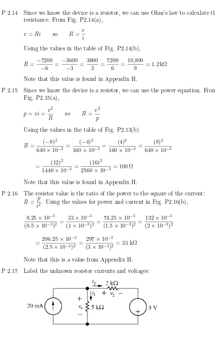
P 2.14
Since we know the device is a resistor, we can use Ohm’s law to calculate the
resistance. From Fig. P2.14(a),
v
=
Ri
so
R
=
v
i
Using the values in the table of Fig. P2.14(b),
R
=
−
7200
−
6
=
−
3600
−
3
=
3600
3
=
7200
6
=
10,800
9
= 1.2 kΩ
Note that this value is found in Appendix H.
P 2.15
Since we know the device is a resistor, we can use the power equation. From
Fig. P2.15(a),
p
=
vi
=
v
2R
so
R
=
v
2p
Using the values in the table of Fig. P2.13(b)
R
=
(
−
8)
2
640
×
10
−3=
(
−
4)
2160
×
10
−3=
(4)
2160
×
10
−3=
(8)
2640
×
10
−3=
(12)
2
1440
×
10
−3=
(16)
22560
×
10
−3= 100 Ω
Note that this value is found in Appendix H.
P 2.16
The resistor value is the ratio of the power to the square of the current:
R
=
p
i
2. Using the values for power and current in Fig. P2.16(b),
8.25
×
10
−3(0.5
×
10
−3)
2=
33
×
10
−3(1
×
10
−3)
2=
74.25
×
10
−3(1.5
×
10
−3)
2=
132
×
10
−3(2
×
10
−3)
2=
206.25
×
10
−3(2.5
×
10
−3)
2=
297
×
10
−3(3
×
10
−3)
2= 33 kΩ
Note that this is a value from Appendix H.
[a]
KCL at the top node:
0.02 =
i1
+
i2
KVL around the right loop:
−
v
o+
v2
−
5 = 0
Use Ohm’s law to write the resistor voltages in the previous equation in
terms of the resistor currents:
−
5000i1
+ 2000i2
−
5 = 0
→
−
5000i1
+ 2000i2
= 5
Multiply the KCL equation by
−
2000 and add it to the KVL equation to
eliminate
i2:
−
2000(i1
+
i2) + (
−
5000i1
+ 2000i2
) =
−
2000(0.02) + 5
→
−
7000i1
=
−
35
Solving,
i1
=
−
35
−
7000
= 0.005 = 5 mA
Therefore,
v
o=
Ri1
= (5000)(0.005) = 25 V
[b]
p20mA
=
−
(0.02)v
o=
−
(0.02)(25) =
−
0.5 W
i2
= 0.02
−
i1
= 0.02
−
0.005 = 0.015 A
p5V
=
−
(5)i2
=
−
(5)(0.015) =
−
0.075 W
p5k
= 5000i
21
= 5000(0.005)
2= 0.125 W
p2k
= 2000i
22= 2000(0.015)
2= 0.45 W
ptotal
=
p20mA
+
p5V
+
p5k
+
p2k
=
−
0.5
−
0.075 + 0.125 + 0.45 = 0
Thus the power in the circuit balances.
P 2.18
[a]
20ia
=
80ib
i
g=
ia
+
ib
= 5ib
ia
=
4ib
50 =
4i
g+ 80ib
= 20ib
+ 80ib
= 100ib
ib
=
0.5 A, therefore,
ia
= 2 A
and
i
g= 2.5 A
[d]
p4Ω
=
i
2g
(4) = 6.25(4) = 25 W
p20Ω
=
i
2a
(20) = (4)(20) = 80 W
p80Ω
=
i
2b