ANALOG ACTIVE NOISE CONTROL SYSTEM
MOHD RUSYDI BIN MOHD SALLEH
This report is submitted in partial fulfillment of the requirement the award of Bachelor Electronic (Wireless Communication) With Honors
Faculty of Electronic and Computer Engineering Universiti Teknikal Malaysia Melaka
ii
UNIVERSTI TEKNIKAL MALAYSIA MELAKA
FAKULTI KEJURUTERAAN ELEKTRONIK DAN KEJURUTERAAN KOMPUTER
BORANG PENGESAHAN STATUS LAPORAN PROJEK SARJANA MUDA II
Tajuk Projek : Analogue Active Noise Control System
Sesi
Pengajian :
4 B E N W
Saya MOHD RUSYDI BIN MOHD SALLEH
……….. (HURUF BESAR)
mengaku membenarkan Laporan Projek Sarjana Muda ini disimpan di Perpustakaan dengan syarat-syarat kegunaan seperti berikut:
1. Laporan adalah hakmilik Universiti Teknikal Malaysia Melaka.
2. Perpustakaan dibenarkan membuat salinan untuk tujuan pengajian sahaja.
3. Perpustakaan dibenarkan membuat salinan laporan ini sebagai bahan pertukaran antara institusi
pengajian tinggi.
4. Sila tandakan ( √ ) :
SULIT*
*(Mengandungi maklumat yang berdarjah keselamatan atau kepentingan Malaysia seperti yang termaktub di dalam AKTA RAHSIA RASMI 1972)
TERHAD** **(Mengandungi maklumat terhad yang telah ditentukan oleh
organisasi/badan di mana penyelidikan dijalankan)
TIDAK TERHAD
Disahkan oleh:
__________________________ ___________________________________ (TANDATANGAN PENULIS) (COP DAN TANDATANGAN PENYELIA)
iii
“I hereby declare that this report is result of my own effort except for quotes as cited in the reference”
Signature : ……….
Name : MOHD RUSYDI BIN MOHD SALLEH
iv
“I hereby declare that I have read this report and in my opinion this report is sufficient in term of the scope and quality for the award of Bachelor of
Electronic Engineering (Wireless Communication) With Honors”
Signature : ………
Name : MR FAUZI BIN ABDUL WAHAB
v
ACKNOWLEDGEMENT
Alhamdulillah, thanks to Allah s.w.t, I have be completed my project of Sarjana Muda for completing my bachelor and getting gain invaluable experience without facing any major problem.
Special thanks are dedicated to my supervisor, Mr Fauzi Bin Abdul Wahad for giving full faith to me to carry this project. Then always give me a support, guidance, instruction and many more on this project.
I also would like to convey and thankful to my family that give me the support and advice. It is very helping me to manage and run this project properly
vi
ABSTRAK
vii
ABSTRACT
viii
TABLE OF CONTENTS
CHAPTER CONTENTS PAGES
PROJECT TITLE i
PSM STATUS VERIFICATION FORM ii
DECLARATION iii
SUPERVISOR VERIFICATION iv
ACKNOWLEDGEMENT v
ABSTRAK vi
ABSTRACT vii
CONTENT viii
LIST OF TABLE xii
LIST OF FIGURE xiii
I INTRODUCTION 1
1.0 Introduction 1
1.2 Objective 2
1.3 Problem Statement 2
1.3.1 Sound Recording 3
1.3.2 Shooting Film 3
1.3.3 Driving Problem 4
ix
CHAPTER CONTENTS PAGES
1.4.1 Literature Review 5
1.4.2 Circuit Design 5
II LITERATURE REVIEW 6
2.1 Fundamentals of Environmental Sound and Noise 6
2.2 Noise Exposure and Community Noise 7
2.3 Effects of Noise on People 8
2.4 Noise Figure 10
2.5 Receiver Noise 10
2.6 Noise Figure Measurement 12
2.7 Sound 12
2.8 Perception of sound 12
2.9 Speed of sound 13
2,10 Sound pressure level 13
2.11 Human voice 14
2.12 Acoustics 15
2.13 Fundamental concepts of acoustics 16
2.14 Sound Reflection 16
2.15 Operation Amplifier 17
2.16 The Perfect Amplifier 18
2.17 Input Bias Current 19
2.18 Power Amplifier 19
2.19 Active Filter 20
2.20 Bandpass Filter 21
III METHODOLOGY OF PROJECT 23
x
CHAPTER CONTENTS PAGES
3.1 Block Diagram of Analog Active Noise 24
Control System 3.1.1 Block Diagram Description 24
3.2 Flowchart of Project 25
IV RESULT AND ANALYSIS 28
4.1 Circuit Involved 28
4,2 Mini Microphone Circuit 28
4.2.1 Mini Microphone Measurement Result 30
4.3 Op-Amplifier Circuit 31
4.4 Audio Mixer Circuit 33
4.4.1 Audio Mixer Measurement Result 33
4.1.2 Audio Mixer Calculation 34
4.5 Power Amplifier Circuit 35
4.6 Active BandPass Filter Circuit 36
4.7 Model Testing 38
4.8 Result Measurement Model System 39
V DISCUSSION AND PROBLEM STATEMENT 40
5.0 Discussion of Overall Project 40
5.1 Problem Statement 42
5.1.1 Design the system 42
5.1.2 Sensor Problem 42
5.1.3 Mixed the Signal Problem 42
5.1.4 Power Amplifier Problem 43
5.1.5 Design the filter circuit 43
xi
CHAPTER CONTENTS PAGES
5.2.1 Design the system 43
5.2.2 Sensor Problem 43
5.2.3 Mixed Signal Problem 44
5.2.4 Power Amplifier Problem 44
5.2.5 Filter Design Problem 44
VI CONCLUSION AND RECOMMENDATION 45
6.0 CONCLUSION 45
6.1 RECOMMENDATION 46
REFERENCES 47
APPENDICES 48
xii
LIST OF TABLE
TABLE NO TITLE PAGES
4.7.1: Survey Frequencies Range (dBA) 39 4.7.2: Testing System Measurement Frequencies 39
xiii
LIST OF FIGURE
FIGURE TITLE PAGES
1.3.1 Jamming Studio 3
1.3.2 Shooting Film 4
1.3.3 Driving Stress 4
2.16: Ideal Operation Amplifier 18
2.17 Input Bias Current 19
2.1.20 Bans-Pass Filter Amplitude Response 22
3.1 Block Diagram of System 24
4.2 Mini Microphone Circuit 29
4.2.1 Output Signal for Mini Microphone Circuit 30
4.3 Op-Amplifier 4 Input 31
4.3.1 Op-Amplifier Design 32
4.3.2 The Op-Amp drive 2 times gain 32
4.4 Audio Mixer Circuit 33
4.4.1 Output Signal for Mixer Circuit 33 4.4.2 Example Summing For Mixer Circuit 34
4.5 Power Amplifier Circuit 35
4.6 Active Band-Pass Filters 36
4.6.1 . Output Measurement for Active Band-Pass Filter 37 4.6.2 Frequencies Response for Active 37
Band-Pass Filter
CHAPTER I
INTRODUCTION
1.1 INTRODUCTION
Nowadays various technologies have been created to facilitate the conduct of human life. Modern technology now covers a variety of system facilities are very useful to mankind. In the rapid progress now, people will sometimes feel threatened by the sound of noise annoying us.
Most people are preferred with comfortable and peaceful surrounding without any noise. The noise will make it difficult to do the work. Especially those students who wish to studying, the baby wants to sleep and etc.
2
1.2 Objective
Before start to build this project, there are some things that need to be considering to achieving the target. The objective of this project is:
a) Identifying the range of frequencies and amplitude level for normal human b) Identifying the range frequencies and amplitude level for normal
environment
c) Build the mini microphone driver circuit as a sensor to detect the sound d) Build the amplifier circuit to amplified the signal from mini microphone
circuit
e) Build the mixer circuit to combine the signal from mini microphone
f) Build the adjustable power amplifier to increase the level signal from mixer circuit
g) Build the low-pass filter to filter the unwanted frequencies signal h) Decides the position of speaker
i) Decides the position of mini microphone
1.3 Problem Statement
3
1.3.1 Sound Recording
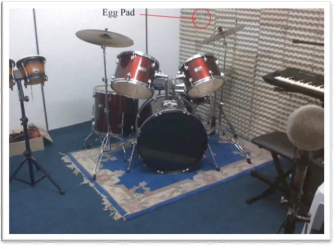
[image:16.612.152.486.236.483.2]Usually those who use jamming studio wanted a good sound quality. Therefore, interference from outside noise will give the bad quality of sound. Most jamming studios still use the old method to absorb the outside noise. Majority the jamming studio still use the egg container for ensure that the outside noise enable to through into the jamming studio.
Figure 1.3.1: Jamming Studio
1.3.2 Shooting Film
4
Figure 1.3.2: Shooting Film
1.3.3 Driving Problem
This system can also be applied into a vehicle for consumers who want to enjoy a quiet and relaxing ride. Now days is very busy with traffic will make drivers impatient and tired. The noise generated by other vehicles will make us feel uncomfortable. Accordingly, this system was designed to reduce pressure on road users. Users can enjoy the comfort driving while not having the luxury vehicle. By this, road traffic accidents may be reduced.
[image:17.612.115.548.491.668.2]
5
1.4 Scope of Project
The scopes are listed to ensure the project is conducted within its intended boundary. It also to ensure the project is heading in the right direction to achieve its objectives, and is listed as follows. Basically, this project is divided into two main parts:
1.4.1 Literature Review
a) Literature review about the range of frequencies that entering into small room via air or other source
b) Doing the research about the normal frequencies including human c) Measurement of the sound reflected that propagate into a small rooms
d) Identifying the type of amplifier that suitable to amplified the signal from source signal
e) Doing the research about type of filter to filter the unwanted frequency signal and setting the range of frequency to filter operate
f) Identifying the position of mini microphone and speaker
1.4.2 Circuit Design
a) Design the mini microphone that act as sensor to detect and absorb the frequencies signal for noise, normal frequencies and human voice
b) Design the amplifier circuit to amplified the signal from the mini microphone c) Design the mixer circuit to combine the signal from amplifier.
d) Design the power amplifier to increase the signal from mixer. The signal was drop from mixer
6
CHAPTER II
LITERATURE REVIEW
2.1 Fundamentals of Environmental Sound and Noise
Sound is mechanical energy transmitted by pressure waves through a medium such as air. Noise can be defined as unwanted sound. Sound is characterized by various parameters that include the rate of oscillation of sound waves (frequency), the speed of propagation, and the pressure level or energy content (amplitude). In particular, the sound pressure level has become the most common descriptor used to characterize the loudness of an ambient sound level. Sound pressure level is measured in decibels (dB), with zero dB corresponding roughly to the threshold of human hearing, and 120 to 140 dB corresponding to the threshold of pain. [9]
7
exerted by a sound corresponding to the sound frequency/sound power level spectrum.[9]
The typical human ear is not equally sensitive to all frequencies of the audible sound spectrum. As a consequence, when assessing potential noise impacts, sound is measured using an electronic filter that de-emphasizes the frequencies below 1,000 Hz and above 5,000 Hz in a manner corresponding to the human ear’s decreased sensitivity to low and extremely high frequencies instead of the mid-range frequency. This method of frequency weighting is referred to as A-weighting and is expressed in units of A-weighted decibels (dBA).[9]
2.2 Noise Exposure and Community Noise
An individual’s noise exposure is a measure of the noise experienced by the individual over a period of time. A noise level is a measure of noise at a given instant in time. However, noise levels rarely persist consistently over a long period of time. Community noise varies continuously over time with respect to the contributing sound sources of the community noise environment. Community noise is primarily the product of many distant noise sources, which constitute a relatively stable background noise exposure, with individual contributors being unidentifiable. Background noise levels change throughout a typical day, but do so gradually, corresponding with the addition and subtraction of distant noise sources and atmospheric conditions. The addition of short duration single event noise sources (e.g., aircraft flyovers, motor vehicles, and sirens) makes community noise constantly variable throughout a day. [9]
8
characteristic of environmental noise is described using statistical noise descriptors. The most frequently used noise descriptors are summarized below: [9]
Leq: The equivalent sound level is used to describe noise over a specified period of time, in terms of a single numerical value. The Leq is the constant sound level which would contain the same acoustic energy as the varying sound level, during the same time period (i.e., the average noise exposure level for the given time period).
Lmax: The instantaneous maximum noise level measured during the measurement period of interest.
Ldn: The energy average of the A-weighted sound levels occurring during a 24 hour period, and which accounts for the greater sensitivity of most people to nighttime noise by weighting noise levels at night (“penalizing” nighttime noises). Noise between 10:00 p.m. and 7:00 a.m. is weighted (penalized) by adding 10 dBA to take into account the greater annoyance of nighttime noises. It should be noted that some jurisdictions also refer to Ldn as DNL.
CNEL: Similar to the Ldn, the Community Noise Equivalent Level adds a 5 dBA “penalty” for the evening hours between 7:00 p.m. and 10:00 p.m. in addition to a 10 dBA penalty between the hours of 10:00 p.m. and 7:00 a.m.
9
2.3 Effects of Noise on People
The effects of noise on people can be placed into three categories:
Subjective effects of annoyance, nuisance, dissatisfaction
Interference with activities such as speech, sleep, learning
Physiological effects such as hearing loss or sudden start
Environmental noise typically produces effects in the first two categories. Workers at industrial plants often experience noise in the last category. There is no completely satisfactory way to measure the subjective effects of noise, or the corresponding reactions of annoyance and dissatisfaction. A wide variation exists in the individual thresholds of annoyance, and different tolerances to noise tend to develop based on an individual’s past experiences with noise.[4]
Thus, an important way of predicting a human reaction to a new noise environment is the way the new noise compares to the existing noise levels to which one has adapted: called the “ambient noise” level. In general, the more a new noise exceeds the previously existing ambient noise level, the less acceptable the new noise will be judged by those hearing it. With regard to increases in A weighted noise level, the following relationships occur:[4]
Except in carefully controlled laboratory experiments, a change of 1 dBA cannot be perceived;
Outside of the laboratory, a 3 dBA change is considered a just-perceivable difference when the change in noise is perceived but does not cause a human response;
A change of at least 5 dBA is required before any noticeable change in human response would be expected.
10
These relationships occur in part because of the logarithmic nature of sound and the decibel system. A ruler is a linear scale: it has marks on it corresponding to equal quantities of distance. One way of expressing this is to say that the ratio of successive intervals is equal to one. A logarithmic scale is different in that the ratio of successive intervals is not equal to one. Each interval on a logarithmic scale is some common factor larger than the previous interval. A typical ratio is 10, so that the marks on the scale read: 1, 10, 100, 1,000, 10,000, etc., doubling the variable plotted on the x-axis. The human ear perceives sound in a non-linear fashion; hence the decibel scale was developed. Because the decibel scale is based on logarithms, two noise sources do not combine in a simple additive fashion, rather logarithmically. For example, if two identical noise sources produce noise levels of 50 dBA, the combined sound level would be 53 dBA, not 100 dBA.
2.4 Noise Figure
Noise Figure is important because it allows the comparison of devices on the basis of how much noise the device adds to the signal as it transits from input to output. All other things being equal, devices which add the least noise are preferable.[3]
2.5 Receiver Noise
11
Noise Factor is defined by:
Noise Figure (Nf) is the Noise Factor expressed in dB:
Noise is a temperature related phenomenon. At absolute zero (-273*C/0K) electron activity stops as does the production of noise. It must know of attempts to reduce noise in receiving systems by cooling the receiving amplifiers. Noise is also related to bandwidth (B). The narrower the bandwidth the less noise. It must be noticed this when switching between modes on a receiver, say from AM/6 KHz B, to SSB/2.4 KHz B to CW/500 Hz B. At each decrease in B the noise drops. Noise power can be expressed as a function of temperature and bandwidth by:
T = Absolute temperature, K (Room temp = 290K) B = Bandwidth, Hz