OPTIMIZATION DESIGN OF SLICING MACHINE USING
DESIGN FOR MANUFACTURING AND ASSEMBLY (DFMA)
METHOD
This report submitted in accordance with requirement of the Universiti Teknikal Malaysia Melaka (UTeM) for the Bachelor Degree of Manufacturing Engineering
(Design) (Hons.)
by
MUHAMAD DALEEL BIN MOHD IDROS
B051010221
890808-07-5193
UNIVERSITI TEKNIKAL MALAYSIA MELAKA
BORANG PENGESAHAN STATUS LAPORAN PROJEK SARJANA MUDA
TAJUK: OPTIMIZATION DESIGN USING DESIGN FOR MANUFACTURING AND ASSEMBLY (DFMA)
SESI PENGAJIAN: 2012/2013 SEMESTER 2
Saya MUHAMAD DALEEL BIN MOHD IDROS
mengaku membenarkan Laporan PSM ini disimpan di Perpustakaan Universiti Teknikal Malaysia Melaka (UTeM) dengan syarat-syarat kegunaan seperti berikut:
1. Laporan PSM adalah hak milik Universiti Teknikal Malaysia Melaka dan penulis. 2. Perpustakaan Universiti Teknikal Malaysia Melaka dibenarkan membuat salinan
untuk tujuan pengajian sahaja dengan izin penulis.
3. Perpustakaan dibenarkan membuat salinan laporan PSM ini sebagai bahan pertukaran antara institusi pengajian tinggi.
(Mengandungi maklumat TERHAD yang telah ditentukan oleh organisasi/badan di mana penyelidikan dijalankan)
Alamat Tetap:
NO 22,JLN BATU JAUHAR 6,TMN
ROWTHER,68100 GOMBAK,SELANGOR
Tarikh: _________________________
Disahkan oleh:
Cop Rasmi:
Tarikh: _______________________
DECLARATION
I hereby, declared this report entitled “Optimization Design of Slicing Machine using Design for Manufacturing and Assembly (DFMA) method” is the results of my own research except as cited in references.
Signature : ………
Author’s Name : MUHAMAD DALEEL BIN MOHD IDROS
APPROVAL
This report is submitted to the Faculty of Manufacturing Engineering of UTeM as a partial fulfillment of the requirements for the degree of Bachelor of Manufacturing Engineering (Design) (Hons.). The member of the supervisory is as follow:
i
ABSTRAK
ii
ABSTRACT
iii
DEDICATION
This report is dedicated to my parents, brothers and sisters for their endless love, support and encouragement. I also dedicate this work to my supervisor and friends
iv
ACKNOWLEDGEMENT
First of all, I would like to express my thankfulness to Allah S.W.T the
Almighty because I manage to finish this Final Year Project on time. With full of His
merciful, now I am writing this report of this project.
I also like to state my gratitude to my supervisor, Engr. Dr Hambali B. Ariff
@ Arep for his assistance and guidance in producing this report and giving me his
constructive comments, guidance, patience and encouragement until the completion
of this report. Besides that, I would like to express my thankfulness to my parents
and friends for their continuous supports and advices in complete the report.
I hope that this project report will fulfill the conditions as requested in Final
Year Project in UTeM.
v
2.2 The Usage of Optimization Design in Improving Design 5 2.3 Design for Manufacturing and Assembly (DFMA) 6
2.3.1 History of DFMA 6
2.3.2 What is DFMA? 6
2.3.3 Advantages of applying DFMA 11 2.3.4 A Case Study from Previous Research 12
2.3.4.1 Texas Instruments 13
2.3.5 Design for Manufacturing (DFM) 15
2.3.6 Design for Assembly (DFA) 16
2.3.7 DFA Methodologies 18
vi 2.3.7.3 The Hitachi Assembleability Evaluation Method 20
2.3.7.4 The Effort Flow Analysis 20
2.3.8 General Design Guidelines for Manual Assembly 21 2.3.8.1 Design Guidelines for Part Handling 21 2.3.8.2 Design Guidelines for Insertion and Fastening 23 2.3.9 The role of DFMA in optimizing design 28
3.3 Project Planning Phase 35
3.3.1 Planning Phase 35
3.3.1.1 Define the objective 35
3.3.1.2 Scope of Project 35
3.3.1.3 Problem Statement 36
3.3.1.4 Literature Review 36
3.3.1.5 Methodology 36
3.3.2 Implementation and Analysis Phase 36
3.3.2.1 DMFA Method Procedure 38
3.3.3 Result Phase 40
vii CHAPTER 4: OPTIMIZATION OF CONCEPTUAL DESIGN OF SLICING
MACHINE
4.1 Introduction 41
4.2 Proposed Original Design of Slicing Machine 42 4.2.1 Detail Original Product for Original Design 42 4.2.1.1 Product Description for Original Design 43 4.2.1.2 Product Structure and Part Quantity for Original Design 47 4.2.1.3 Bill of Materials for Original Design 51 4.2.1.4 Part Functions and Critics for Original Design 53 4.2.2 DFMA Analysis for Original Design 59 4.2.2.1 Design for Manufacturing (DFM) Analysis for Original 59
Design
4.2.2.2 Design for Assembly (DFA) Analysis for Original Design 61
4.3 Proposed Redesign of Slicing Machine 63
4.3.1 Part Elimination from Original Design 63 4.3.2 Detail Redesign Product for Proposed Design 64 4.3.2.1 Product Description for Proposed Design 64 4.3.2.2 Product Structure for Proposed Design 66 4.3.2.3 Bill of Materials for Proposed Design 72 4.3.2.4 Part Functions and Critics for Proposed Design 73 4.3.3 DFMA Analysis for Proposed Design 77 4.2.2.1 Design for Manufacturing (DFM) Analysis for Proposed 77
Design
4.2.2.2 Design for Assembly (DFA) Analysis for Proposed 79 Design
viii
CHAPTER 6: CONCLUSION AND RECOMMENDATIONS 6.1 Conclusion 93
ix
LIST OF TABLES
2.1 DFMA results from 117 published case studies involving 56 companies data as of April 1999
10
2.2 Comparison of Original Design and New Designs of the Reticule Assembly
14
4.1 Bill of Material of overall number of part of original design 51 4.2 Parts functions and critics of original design 53 4.3 Material and process of each part of original design 59 4.4 Assembly Difficulties for Original Design of Slicing Machine 62
4.5 Eliminated Parts from Original Design 63
4.6 Bill of Material of overall number of part of improved design 72 4.7 Parts functions and critics of improved design 74 4.8 Material and process of each part in improved design 77 4.25 Assembly Difficulties of improved design 80
5.1 Suggestion for incorporate integral fastening elements 85 5.2 Suggestion for combine connected items 85 5.3 Suggestion for reduce the number of items in the assembly 85 5.4 Suggestion for reduce separate operation times 86 5.5 Suggestion for design locating into mating parts of the assembly 87
5.6 Suggestion for add assembly features 87
5.7 Suggestion for redesign the assembly 87
5.8 Suggestion for redesign of the items to eliminate or reduce of their handling difficulties
87
5.9 Suggestion for redesign of the individual assembly items to eliminate the need for grasping tools
88
5.10 Suggestion for redesign of the individual assembly items to eliminate handling difficulties causing the items require two hands
x 5.11 DFMA results comparisons between original and new improved
design of product
xi
2.4 Survey on the importance of reductions produced by DFMA 11 2.5 Time to deliver comparison between DFMA+CE and the
Traditional Methods
12
2.6 Reticule assemblies – original design 13
2.7 Reticle assemblies – New Design 14
2.8 Geometrical features affecting part handling 21 2.9 Some other features affecting part handling 22 2.10 Incorrect geometry can allow part to jam during insertion 23 2.11 Provision of air-relief passages to improve insertion into blind
holes
23
2.12 Design for ease of insertion – assembly of long stepped bushing into counter bored hole
24
2.13 Provision of chamfers to allow easy insertion 24
2.14 Standardize parts 25
2.15 Single-axis pyramid assemblies 25
2.16 Provision of self-locating features to avoid holding down and alignment
26
2.17 Design to aid insertion 26
2.18 Common fastening methods 27
2.19 Insertion from opposite direction requires repositioning of assembly
27
xii
3.1 Project Planning Phase 34
3.2 Design For Assembly (DFA) Software 37
3.3 Design For Manufacture (DFM) Software 37
3.4 DFMA Method Procedures 39
4.1 View for top layer and bottom layer subassembly for original design of slicing machine
42
4.2 Views of portions subassembly of original design
43
4.3 Product structure of original design 45
4.4 Assembly drawing of original design 46
4.5 Framework of original design 46
4.6a Top Layer of original design 47
4.6b Top Layer of original design 47
4.7a Bottom Layer of original design 48
4.7b Bottom Layer of original design 48
4.8 Front Side of original design 49
4.9 Back Side of original design 49
4.10 Right Side of original design 50
4.11 Left Side of original design 50
4.12 Top Side of original design 51
4.13 Design for Manufacturing Window of original design 60 4.14 Design for Assembly Window of original design 61 4.15 DFA analysis on the framework of original design 62 4.16 Views of the top layer and the bottom layer of improved design 65 4.17 Views of the right side, left side, front side, back side and the top
side of the redesigned slicing machine of improved design
65
4.18 Product structure of improved design 67
4.19 Assembly drawing of improved design 68
4.20 Framework of improved design 68
4.21 Top Side of improved design 69
xiii
4.23 Front Side of improved design 70
4.24 Back Side of improved design 70
4.25 Right Side of improved design 71
4.26 Left Side of improved design 71
4.27 Top Layer of improved design 72
4.28 DFM window for Redesign of Slicing Machine 78 4.29 DFA Window for Redesign of Slicing Machine 79 4.30 DFA analysis on the framework of improved design 80
5.1 Before and After of Slicing Machine 89
xiv
LIST OF ABBREVIATIONS, SYMBOLS AND NOMENCLATURE
DFMA = Design for Manufacture and Assembly
DFA = Design for Assembly
DFM = Design for Manufacture
BD-DFA = Boothroyd Dewhurst Design for Assembly
AEM = Assembly Evaluation Method
OD = Optimization Design
KTP = Knowledge Transfer Program
BDI = Boothroyd Dewhurst Inc.
CE = Concurrent Engineering
ASF = Assembly Sequence Flowchart
MOP = Measures of Performance
UTeM = Universiti Teknikal Malaysia Melaka
PSM 1 = Projek Sarjana Muda 1
PSM 2 = Projek Sarjana Muda 2
BDI = Boothroyd Dewhurst Inc
IPM = Interior Point Method
1 This chapter discusses the background of the project, problem statement, objective and scope of the project.
1.1 Background of Project
This project is actually related to the industry based. In other words, this project solve a problem that occurs in a factory. TR Technology Sdn Bhd is the factory that was selected for collaboration with this project. TR Technology Sdn. Bhd. is located at Seksyen 16, Shah Alam, Selangor. TR Technology Sdn Bhd is a factory which runs a business based on the process of stamping and cutting. Among the activities run in this factory is the process of cutting rubber sheets. In accordance with the process, the problem that arises is the cutting method of the sheets, which they are still using old-fashioned clasp knives. By using this outdated method, it has had wasted the time and cost, the workers’ energy, productivity and the output of the product. To solve of the factory problems, DFMA concept is chosen as a main concept for this project.
The DFMA concept is chosen due to the following factors :-
a) It can increase the quality of new produces during the developmental period, including design, technology, manufacturing and service.
b) It can decrease the cost, including the cost of design, technology, manufacturing, delivery, technical support and discarding.
2 c) Shorten the development cycle time, including the time of design, manufacturing
preparing, and repeatedly calculation. (Xie, 2002).
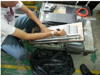
1.2 Problem Statement
At the TR Technology Sdn. Bhd, the rubber sheets cutting process is still done by using the conventional method which is using clasp knives (refer to Figure 1.1).
Figure 1.1: Conventional Cutting Process
Therefore, TR Technology Sdn. Bhd. has asked UTeM committee to assist in developing a slicing machine that can reduce wastage material, labor working duration and increase the productivity. The problem arising here is to design a slicing machine that is not yet available in the market. Besides that, the new design of slicing machine has to meet the requirements of the clients, TR Technology Sdn. Bhd. There are also other problems that occurred at this factory. There are :-
a) Ineffective cost-down activities and strategies.
b) Requirement for better improvement in productivity to be competitive in market need further concerted effort.
3
1.3 Objectives
The main objective of this project is to improve the design of the slicing machine. Specific objective as follows
:-a) To reduce the number of parts through DFMA method.
b) To identify the most appropriate material and process for the product. c) To improve the original design by using DFMA method.
1.4 Scope of Project
The scopes of this project are set at an early stage of the project to ensure that the objective of the project can be achieved. The scopes for this project are
:-a) To design a 3D modeling using Solidwork software.
b) To use a Boothroyd-Dewhurst software for product evaluation.
4 This chapter covers on the explanation about Design for Manufacturing and Assembly (DFMA) and Optimizing Design (OD). Besides that, this chapter is also highlight the relationship between DFMA and OD.
2.1 Optimization Design (OD)
According to Monge (2001), such design optimization is derived from a formula and solved to gain insight into the converter design tradeoffs and particularities. Until then, a discrete optimization approach is comprised from a genetic algorithm to develop a completely automated user-friendly software design tool, capable of providing globally optimum designs for systems with different sets of specification, in a period of time.
Engineering design optimization is an emerging technology, with its application both shortens design-cycle time and finds new designs that are not only feasible, but optimal, based on the design criteria. In the early days, optimization design had to begin by deriving a formula for design requirements. After that, an initial design is synthesized which must be tested against the requirements, hence creating a prototype and performing experiments. A build-up of a computer model may follow, using one of the many engineering analysis codes, and then the design is validated experimentally since these codes are not accurate. Such a design is found to have defaults in some parts, it is then altered and the process repeats again. The process is executed on and on until the requirements are met or changes are made to fit
5 performance. This concludes that the process is time consuming and seldom produces the perfect design, just a feasible one (Johnson, 2004).
Optimization methods are formulated to bring out the best values of system design and operating policy variables – values that will lead to the optimum level of performance. When combined with more detailed and accurate simulation methods in short of building an actual model, can be the primary way of estimating the likely impacts of system designs and operating policies (Loucks, 2005).
Optimization can be a subject of dealing the problems of minimizing or maximizing a
certain function in a finite dimensional Euclidean space over a subset of that space which is usually determined by functional inequalities (Anjos and Zhang, 2006).
2.2 The Usage of Optimization Design in Improving Design
With engineering design optimization, it reduces both the time for the design iteration loop and finds the optimum design based on specifications. Unlike the traditional process, the iteration loop is computerized. An optimization problem is posed for which the design variables, the design objectives and all constrai8nts are specified. An appropriate engineering analysis code is combined with an optimization algorithm, which serves as the design modifier (Johnson, 2004).
6
2.3 Design for Manufacturing and Assembly (DFMA)
2.3.1 History of DFMA
Before the Second World War, Ford and Chrysler use the DFM philosophy in their design and manufacturing process of the weapons, tanks and other military products. It was in the beginning of the 1970’s, when Dr. Geoffrey Boothroyd and Dr. Peter Dewhurst, who founded the Boothroyd Dewhurst Inc. (BDI) in1982, they were the pioneers in this new technology. The “DFMA” in actual became their company trademark. They created and developed the DFMA concept which is used in developing the products of their company, the DFMA software system. Currently these programs are used to help the design in almost all the industrial fields including circuit boards, with manual assembly, with robotic assembly, and with machining. They also do a lot of work examining the economic justification of each design revision (Xie, 2005).
2.3.2 What is DFMA?