SUPERVISOR DECLARATION
“I hereby declare that I have read this thesis and in my opinion this report is sufficient in terms of scope and quality for the award of the degree of
Bachelor of Mechanical Engineering (Thermal-Fluids)”
Signature: ………... Supervisor: Mohd Noor Asril Bin Saadun
CONTAMINANT REMOVAL FOR DIFFERENT GEOMETRY OF CAVITIES WITH HIGH REYNOLDS NUMBER USING FLUENT
MUHAMMAD ZULHAKIM BIN SHARUDIN
This report is submitted in partial fulfillment of the requirement for the degree of Bachelor Mechanical Engineering with Honors' (Thermal-Fluids)
Faculty of Mechanical Engineering Universiti Teknikal Malaysia Melaka
ii
DECLARATION
"I hereby declare that the work in this report is my own expect for summaries and
quotations which have been duly acknowledge."
Signature ………
Author: Muhammad Zulhakim Bin Sharudin
iii
Special for my beloved
Father and Mother,
Sharudin bin Che Ya and Zainab binti Razali
iv
ACKNOWLEDGEMENT
I would like to express my sincere gratitude to my loving parents, Mr. Sharudin bin Che’ Ya and Mrs. Zainab binti Razali. Not to forget are my siblings and relatives who have given me morale and economic supports during the research.
My parents have given their love, dream and sacrifice throughout my life. I am really
thankful for their sacrifice, patience, and understanding that were much-needed to
make this work possible. Their sacrifice had inspired me from the day I learned to
read and write until what I have become now. I cannot find the appropriate words
that could properly describe my appreciation for their devotion, support and faith in
my ability to achieve my dreams
A great thanks are due to my supervisor, Mr. Mohd Noor Asril bin Saadun and my
panel. Dr. Shamsul Anuar bin Shamsudin for his invaluable guidance, continuous
encouragement and constant support in making this research possible. I really
appreciate his guidance from the initial to the final level that enabled me to develop
an understanding of this research thoroughly. Without his advice and assistance it
would be a lot tougher to complete. I also sincerely thanks for the time spent
proofreading and correcting my mistakes. I must acknowledge as well the many
friends, lectures, technicians, and many others who assisted, advised, and supported
me.
Lastly I would like to thank any person who contributes to my final year project
directly or indirectly. Their comments and suggestions were crucial for the
v
ABSTRACT
A preliminary Computational Fluid Dynamics (CFD) study on the effect of
high Reynolds number flows toward the contaminant removal in the cavity was
carried out. Based on the simulation of the CFD, the two dimensional (2D) model
analyses of the flow characteristics was done using the numerical solution of the
Navier-Stokes equations based on the finite difference method. The flow
characteristics in the cavity and the driven flow were modeled via turbulence model.
The attention of this study focuses on the effect of different high Reynolds number
flow in removing the contaminant in the cavity. As the parameter of the cavity, the
different type of geometry and different aspect ratio of the geometry was used. The
result shows the comparison in term of the flow visualization between each model
vi
ABSTRAK
Kajian awal Bendalir Dinamik Berkomputer (CFD) yang dijalankan
mengenai kesan aliran cecair dengan nombor Reynolds tinggi terhadap penyingkiran
bahan cemar dalam ruang rongga. Berdasarkan simulasi CFD, model analisis dua
dimensi dengan ciri-ciri aliran yang telah dilakukan dengan menggunakan
penyelesaian berangka Navier-Stokes berdasarkan kaedah pembahagian
takterhingga. Ciri-ciri aliran dalam rongga dan aliran terdorong dimodelkan melalui
model persamaan gelora. Skop kajian ini tertumpukepada kesan perbezaan aliran
nombor Reynolds tinggi dalam penyingkiran bahan cemar dalam rongga. Sebagai
parameter rongga, jenis geometri yang berbeza dan aspek nisbah geometri yang
berbeza telah digunakan dalam kajian ini. Keputusan menunjukkan perbandingan
dari segi visualisasi aliran antara setiap model digunakan.dengan parameter yang
vii
TABLE OF CONTENTS
CHAPTER CONTENTS PAGES
DECLARATION ii
DEDICATION iii
ACKNOWLEDGEMENT iv
ABSTRACT v
ABSTRAK vi
TABLE OF CONTENTS vii
LIST OF TABLES x
LIST OF FIGURES xi
LIST OF APPENDICES xiii
CHAPTER I
INTRODUCTION 1
1.1 Background 1
1.2 Problem Statement 2
1.3 Objective 3
1.4 Scope 3
CHAPTER II
LITERATURE REVIEW 4
2.1 Introduction 4
2.2 History Of The Computational Fluid Dynamics
(CFD)
5
2.3 High Reynolds Number Flow 7
viii
CHAPTER CONTENTS PAGES
2.5 Geometry Of Cavity 10
2.6 Aspect Ratio Of The Geometry Cavity 12
CHAPTER III
METHODOLOGY 14
3.1 Introduction 14
3.2 Physical Model 16
3.2.1 Channel Modeling 16
3.2.2 Geometry of Cavities Model 18
3.2.3 Aspect Ratio of Cavities Model 20
3.2.4 Boundary Condition 22
3.2.4.1 Inlet of the channel 22
3.2.4.2 Outlet of the channel 23
3.3 Numerical Scheme 23
3.3.1 Reynolds-averaged Navier-Stokes (RANS)
24
3.3.2 Finite Difference (FD) Method 25
3.3.3 Turbulence Modeling 26
CHAPTER IV
RESULT AND DISCUSSION 29
4.1 Introduction 29
4.2 Flow Characteristic In Different Shapes Of Cavity 30
4.2.1 Aspect Ratio 2 (AR=2) 31
4.2.2 Aspect Ratio 3 (AR=3) 33
ix
CHAPTER CONTENTS PAGES
4.3 Effect Of High Reynolds Number In Different
Aspect Ratio Of Cavities
37
4.3.1 Square Cavity of Geometry 38
4.3.2 Semi-Circle Cavity of Geometry 41
4.3.3 Triangle Cavity of Geometry 44
4.4 Static Pressure Difference in the Cavity Geometry 46
4.4.1 Static Pressure Different in Square Cavity 47
4.4.2 Static Pressure Different in Semi-Circle
Cavity
49
4.4.3 Static Pressure Different in Triangle
Cavity
51
CHAPTER V
CONCLUSION AND RECOMMENDATION 53
5.1 Conclusion 53
5.2 Suggestion And Recommendation 55
REFERENCES 56
x
LIST OF TABLES
NO. TITLE PAGES
xi
LIST OF FIGURES
NO. TITLE PAGES
2.1 The relation in between the Computational Fluid
Dynamics
6
3.1 The channel with the opening of the cavity slots 17
3.2 The model of the channel with explanation 17
3.3 Three different geometry cavities with the channel 19
3.4 The model of channel with the triangular geometry of
cavity
20
3.5 The model of channel with the semi-circular geometry
of cavity
21
3.6 The model of channel with the rectangular geometry of
cavity
21
4.1 The comparison of simulation using aspect ratio cavity
AR=2
31
4.2 The comparison of simulation using aspect ratio cavity
AR=3
33
4.3 The comparison of simulation using aspect ratio cavity
AR=4
35
4.4 The comparison of simulation using square cavities
geometry
38
4.5 The comparison of simulation using semi-circle cavities
geometry
41
4.6 The comparison of simulation using triangle cavities
geometry
xii
NO. TITLE PAGES
4.7 The comparison of static pressure graph between square
cavities geometry
47
4.8 The comparison of static pressure graph between
semi-circle cavities geometry
49
4.9 The comparison of static pressure graph between
triangle cavities geometry
xiii
LIST OF APPENDICES
NO TITLE PAGES
1 Appendix 1 59
2 Appendix 2 60
3 Appendix 3 61
1
CHAPTER I
INTRODUCTION
1.1 BACKGROUND
In the natural environment such as lakes, rivers and drains, the same situation
as the presence of cavity can clearly be seen. The points of interest are at the flows
deal with the contaminant problem that arises in the cavities. The toxic, the
suspended sediment and pollutant may accumulate which can the problem the flow
and harmful to the environment. For the instant, the ejection of the contaminant from
the cavity need to be done and can bring the solution to the problems.
In the term of flow, the incoming boundary layer of the flow in the leading edge of
the cavity may be in the laminar or turbulent flow. But most of the time, real
situations deal with turbulence flows. The Reynolds number will determine the kind
of flow that creates in the streamline.
Most engineering applications dealing with the flow in a channel are encountered
with the contaminant in the cavity. An example is the pipeline of fluid. The
2
is the location of the cavity. The particles of contaminant contained in the fluid flow
will stuck and accumulate in this cavity. By then, the contaminant had to be removed
because it can create a problem in the pureness of the fluid and change the flow of
the fluid in terms of pressure and velocity.
The solution to the contaminant removal can be done by using pigging technique in
the pipeline but it cannot be used in small diameter pipelines and in the long
continuous pipelines. The next alternative is the hydrodynamic cleaning technique
that uses the flow itself as the medium to remove the contaminant in the specific
flow conditions. This project tries to study the contaminant removal using specific
flow conditions by the Computational Fluid Dynamics (CFD) analysis.
1.2 PROBLEM STATEMENT
One of the alternative methods of cleaning process of contaminant in
pipelines that has widely used this day is by hydrodynamics cleaning. The formation
of re-circulating vortices in the cavities is different and it leads to either enhancing or
preventing the removal of contaminant based on the geometry and aspect ratio of the
cavities[1]. It also depends on the type of flow and Reynolds numbers of the flow[2].
Many researchers are investigating this kind of hydrodynamic contaminant removal
but most of them are reported to use the laminar boundary layer upstream or low
Reynolds number flow [3]. In a real situation, the process involves a turbulent
incoming flow boundary condition in the leading edge of the stream. The experiment
and simulation studies for flows with high Reynolds number are still lacking. The
work will study the effects of the hydrodynamic removal contaminant using high
Reynolds number of flow based on three different geometry of cavity and each of the
geometry have three different aspect ratios. As the alternative study approach to the
high cost experimental study, this project will be done on fully computational
scheme of CFD using ANSYS FLUENT software to provides the extensive
3
1.3 OBJECTIVE
The objectives of this study are:
1. To investigate the effect of high Reynolds number flow on hydrodynamic
removal of contaminants.
2. To understand the flow characteristics of high Reynolds number in the
different geometry of cavities.
3. To determine the relationship between the effect of high Reynolds numbers
with different aspect ratio of the cavities.
1.4 SCOPE OF STUDY
The scopes of this study are:
1. Analysis of the effect of flow characteristic by using FLUENT.
2. Study on three different geometry of cavities which is semi-circular,
triangular, and rectangular.
3. Study on the three different aspect ratio of each geometry cavity which is 2,
3, and 4.
4. Concentrate on the two dimensional (2D) analysis with the incompressible
4
CHAPTER II
LITERATURE REVIEW
2.1 INTRODUCTION
The literature review searches for existing information of the related topics
that have been discovered by other researchers to be used as a guide and reference
for the current work. All the information and reference that used in this study was to
be used as working steps in order to provide the added value and produce good
additive to this study. This study sources also based on the same aspects or
analogous of the previous study that taken the information from the example of
journals, internet resources, experiments report and references book.
In this chapter, the study of contaminant removal for the different geometry of cavity
used, attached and elaborated all the information to this chapter by regarding the
history of the Computational Fluid Dynamics (CFD), high Reynolds number of flow,
removing the contaminant, the geometry of cavities and the aspect ratio of the
5
2.2 HISTORY OF THE COMPUTATIONAL FLUID DYNAMICS (CFD)
From the early 1970’s, CFD was started during the time. The complex combination between the mathematical calculation and physic analysis, create the
simulation of fluid flows with the extension of computer sciences. The beginning of
CFD was triggered by the sources availability of computer. In the advance of CFD, it
increased with the connection of the evolution of the supercomputer technology.
The transonic flow has become among the first application used CFD as the method
based on the non-linear potential equation solution. On the early 1980’s, the first study of two dimensional (2D) analysis has been solved and then the study of three
dimensional (3D) equation analysis started to be introduced in CFD. The rapid
increasing of the computer technology created the faster supercomputer that can be
possibly calculated and computed the numerical equation of the flows.
In the middle of 1980’s, CFD started to shift the focus to the significant simulation of viscous flows by the Navier-Stokes Equations that highly demanding at that time.
The evolutions of CFD also take the turbulence model into the new chapter of study
with the different degree of numerical complexity and accuracy. By the time the
leading edge in turbulence modeling was represented by the Large Eddy Simulation
(LES) and the Direct Numerical Simulation (DNS), the usable of those approach is
6
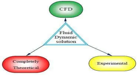
Figure 2.1: The relation in between the Computational Fluid Dynamics.
For this present day, many numerical techniques were developed for CFD is
used in solving the study in the fields of aircraft, turbomachinery, car, and ship
design. CFD is also applied in, astrophysics, meteorology, and oceanography in oil
recovery. Thus, CFD becoming the important design and substantial research tool in
engineering. The complex geometry cases can be treating due to the advance of
numerical method solution and computer technology. By taken account those thing,
the simulation of viscous flows with large scale size can be completed in the short
period of time.
CFD is method that related to the solution of the equation of motion of the fluid and
also concerned with the interaction of the fluid with the solid bodies. The equation
involved the Euler equation that is the equation of motion of inviscid fluid and the
Navier-Stokes equation that is for the viscous fluid as it well-known as the governing
equations. There are three fundamental principles that need to be followed to govern
the physical aspect of any fluid flows. These are that the:
1. Mass is conserved.
2. Energy is conserved.
3. Newton’s second Law is observed.
All the principle is expressed in terms of partial differential equations of
mathematical modeling. In the other meaning, CFD is the part of replacing partial
7
these numbers in the space and time to obtain the complete numerical description of
the flow field. The objective of most engineering analysis in the close form or open
form is in quantitative description of the problem such as numbers.
2.3 HIGH REYNOLDS NUMBER FLOW
Most flows experience some turbulence flow. Some of them were exhibiting
with very high Reynolds numbers and some of them were not high. Such as the
atmosphere of earth has a condition of extremely high Reynolds number. It is the
same with many engineering applications on the aircraft, car, ship and also the
pipeline flow. In order to study the effect of the high Reynolds number toward the
contaminant removal, the high Reynolds numbers needs to be better understood[6].
Nowadays, a lot of interest in the study have push CFD to used the higher Reynolds
number in the studies involve with the flow such as the wind loading on structures,
controlling the dispersion of the contaminant inside a compound and characterizing
the flow in the engineering application environment. Many classic works
demonstrated the separation of the flow, stationary vortices structures, and the vortex
shedding. All of these in were difficult to model well[6 ][7][9][10].
For creating a higher Reynolds number flow, it means that there is need to have
larger ratios between the smallest scale in the flow and the higher scale of the flows.
Classically, there have some limitation in creating a quality high Reynolds number
flow in the experiment such as the lack of the apparatus that can generate the
turbulence flows and the low availability of measurement techniques. By then, using
the simulation of CFD is the better option for the study of high Reynolds number
compared to the conduct the experiments.
In the previous case study of contaminant, the removal of the contaminant, the rapid
washout is highly desirable. It has achieved the high flow rates and resulting in high
8
number flows, remain similar for different flow rates leading to similar transport
pattern in example of the air flow characteristics. At the level of turbulence, airflow
profiles of the turbulent flow will only change in their magnitude not in the term of
shapes[11].
For high Reynolds number flow, the inertial effect of the flow will be the main factor
in determine the contaminant removal. Therefore, the inlet velocity boundary
conditions need to be accurate. It is necessary to carefully model the flow at
atmospheric Reynolds number using higher accuracy but at the same time readily
achievable to reproduce the desired features of the high Reynolds number flow. It
also included the grid resolution, technique to systematically relaxing the grid and a
few of modeling assumptions to characterize the fidelity[12].
In this contaminant removal for different geometry of cavity with high Reynolds
number study, the high Reynolds number and turbulent flow is the most important
since it will bring the effect to the modeling of the simulation and in the same time it
will affect the result. The properties of high Reynolds number turbulent flow are
connected with the transport dynamics of the large scales. Therefore it is important
to focus on computing the resources on captured the scales accurately. In the
perspective of application on the hydrodynamic contaminant removal, accurate and
time dependent may be all it needed and by choosing the grid size for a uniform
fashion using the boundary in between the large scales and the inertial range is
9
2.4 REMOVING THE CONTAMINANT
Drag force is the force component that resistant to the opposite direction of
the flow velocity. In other meaning, the drag force is the force of flow friction over a
body and it is increasing with the increase of speed. For the essential, the drag force
on the any type of body is proportional to the square of relative speed in between the
fluid and the body and also proportional to the fluid density.
The drag force coefficient in the curtain body depends on the direction of the fluid
flow and the Reynolds number. The variation of the Reynolds number within the
range of interest is usually small but depending on the type of study. For the high
Reynolds number, the drag force coefficient cannot treat as the constant all the time
because it is dependent to the direction of the flow as the high Reynolds number will
create the turbulence flow and direction of the flow is not consistence. The
streamline body and the boundary layer around the body that attached to the surface
of the body will cause a low drag force coefficient. The high drag force will result
the wake.
The drag force coefficient of the object such as particle and contaminant cannot be
constant but it is a function of the Reynolds number. At the high Reynolds number,
the flow around the object will change from the transition to the turbulent especially
at the point where separation from the surface object. With this flow separation, the
Reynolds number will be high for small object and low viscosity fluid. The drag
force coefficient is different in between the type of the fluid.
There is study of the hydrodynamic resistance to particle transportation. It research
for the axisymetric creeping flow caused by the particle migrating in the cavity.
From the drag force on the particle was calculated, it found that the particle
experiencing a local maximum drag force larger than the particle that located in the
center of cavity when passing through an aperture. Other than that, the drag force
10
result, for connected cavities, the drag force is smaller than the corresponding
system.[19]
Tsong et el. (2006) has study about the contaminant removal from the cavity. It has
explaining the detail behavior of solid particles in lid-driven cavity flow in between
the size of micro to macro of the particles in term of experimental result[20]. The
connection and interaction between fluid and solid in the nature was complicated
causes the study of it is still less. The formation of the vortices in the cavity by the
flow was believed that it can maximizing or minimizing or also can preventing the
contaminant removal depends on the parameter of flow and also the characteristics
of the contaminant itself[3].
This work focuses on removing the contaminant by using the high Reynolds number
water flows and study the relationship of the drag forces, particles that contain in the
water flow and also how it link to the removing of the contaminant by the formation
of vortices create by the flow at the cavity.
2.5 GEOMETRY OF CAVITY
Cavity is the hollow space in between the area within the body or
surface[14]. In the channel or piping, the cavity can be observed in its curtain surface
or body. The presence of cavity usually cannot be avoided because a cavity is
created when it comes to the interconnection between two connecting pipes.
Sometime, in welding joint also created the cavity
Studies have been conducted by used flow in the boundary layer as the study to the
cavity problem case. The solutions to the problems can be implemented in the real
world such as oil and gas piping system, aeronautical and automobile part, and
building structural. Each of the cavity is different in shape and geometry and bring
the different kind of problem occur based on the differential situation. Most of the
past study and research, the rectangular geometry was the favorite kind of geometry