GRAPHENE – BASED VIVALDI ANTENNA USING CST SOFTWARE
MUHAMMAD SHAFIQ BIN ROSLI
This Report Is Submitted In Partial Fulfillment of Requirements For The Bachelor Degree of Electronic Engineering (Industrial Electronic)
Fakulti Kejuruteraan Elektronik dan Kejuruteraan Komputer Universiti Teknikal Malaysia Melaka
UNIVERSTI TEKNIKAL MALAYSIA MELAKA FAKULTI KEJURUTERAAN ELEKTRONIK DAN KEJURUTERAAN KOMPUTER
BORANG PENGESAHAN STATUS LAPORAN PROJEK SARJANA MUDA II
Tajuk Projek : ………
Sesi
Pengajian :
Saya ……….. (HURUF BESAR)
mengaku membenarkan Laporan Projek Sarjana Muda ini disimpan di Perpustakaan dengan syarat-syarat kegunaan seperti berikut:
1. Laporan adalah hakmilik Universiti Teknikal Malaysia Melaka.
2. Perpustakaan dibenarkan membuat salinan untuk tujuan pengajian sahaja.
3. Perpustakaan dibenarkan membuat salinan laporan ini sebagai bahan pertukaran antara institusi pengajian tinggi.
4. Sila tandakan ( √ ) :
SULIT* *(Mengandungi maklumat yang berdarjah keselamatan atau kepentingan Malaysia seperti yang termaktub di dalam AKTA RAHSIA RASMI 1972)
TERHAD** **(Mengandungi maklumat terhad yang telah ditentukan oleh organisasi/badan di mana penyelidikan dijalankan)
TIDAK TERHAD
Disahkan oleh:
__________________________ ___________________________________ (TANDATANGAN PENULIS) (COP DAN TANDATANGAN PENYELIA)
iii
“Saya akui laporan ini adalah hasil kerja saya sendiri kecuali ringkasan dan petikan yang tiap-tiap satunya telah saya jelaskan sumbernya.”
Tandatangan : ……….
Nama Penulis : ……….
iv
“Saya/kami akui bahawa saya telah membaca karya ini pada pandangan saya/kami karya ini adalah memadai dari skop dan
kualiti untuk tujuan penganugerahan Ijazah Sarjana Muda Kejuruteraan Elektronik (Elektronik Telekomunikasi).”
Tandatangan : ……….
Nama Penyelia : ……….
v
vi
ACKNOWLEDGMENTS
I would like to thank my supervisor, Mr. Azman Bin Awang Teh for his support, guidance and supervision throughout the process to complete and improvement this thesis.
I also would like to thank Dr. Maisarah Binti Abu and Mdm. Zaharah Binti Manap as my panel for PSM I and Mdam. Norbayah Binti Yusop and Mdm. Zaharah Binti Manap as my panel for PSM II for their valuable comment about my project during the presentation of PSM I and PSM II. Also thank to Faculty of Electronic and Computer Engineering (FKEKK) for the provision of resources and facilities during this research process.
I am grateful to all my friends for their encouragement and valuable assistance to accomplish this work.
vii
ABSTRACT
In this thesis, the performance of Vivaldi antenna are studied based on the two different materials that build up the antenna that is graphene and copper. Performance of the Vivaldi antenna is investigated by parametric study to get the optimized design based on the return loss response. The results of performance of Vivaldi antenna are only cover the simulation and the simulations are using CST Studio Suite software. Two Vivaldi antennas are design for the operating frequency range from 8 to 12 GHz frequency band with return loss better than 10 dB. These two antennas are design based on parametric study result. Both antennas are used microstrip to slotline transition feeding. This antenna is constructed using FR4 substrate which has dielectric constant ∈r 4.30 and
viii
ABSTRAK
Dalam thesis ini, prestasi Vivaldi antenna dikaji berdasarkan dua bahan berbeza yang diguna untuk membuat antenna iaitu graphene dan tembaga. Prestasi Vivaldi antenna dikaji dengan mengunakan teknik kajian parametrik untuk mendapatkan reka bentuk antenna yang optimum berdasarkan tindak balas kembali kehilangan. Keputusan prestasi Vivaldi antenna ini hanya merangkumi bahagian simulasi dan simulasi menggunakan perisin CST Studio Suite. Dua Vivaldi antenna direka untuk julat frekuensi opersi dari 8 hingga 12 GHz dengan kembali kehilangan lebih baik daripada 10dB. Dua antenna ini direka berdasarkan keputusan dari kajian parametrik. Kedua-dua antenna menggunakan jenis peralihan microstrip ke slotline. Antenna ini dibina daripada papan cetak FR4 substart yang mempunyai pemalar dielektrik ∈r 4.30 dan bahan
ix
TABLE OF CONTENTS
CHAPTER SUBJECT PAGE
DEDICATION v
ACKNOWLEDGMENTS vi
ABSTRACT vii
ABTRACT viii
TABLE OF CONTENTS ix
LIST OF TABLES xi
LIST OF FIGURES xii
I PROJECT INTRODUCTION
1.1 Introduction 1
1.1.1 Vivaldi Antenna Design 2
1.1.2 Transmission Line 4
1.1.3 Parameter of Antenna 5
1.1.4 Graphene 8
1.2 Objective 9
1.3 Problem Statement 9
1.4 Scope 10
II LITERATURE REVIEW
2.1 Graphene 11
2.2 Antenna 13
2.2.1 Size of Antenna 14
2.2.1.1 Opening length and width 14
2.2.1.2 Antenna length 15
2.2.1.3 Antenna width 15
2.2.1.4 Slotline width 16
x
2.2.1.6 Stripline and slot stub length 17 2.2.1.7 Uniform slotline length 17
2.2.1.8 Edge offset 18
2.2.2 Transmission Line 18
2.2.3 Substrate Material 19
III METHODOLOGY
3.1 Substrate Material 21
3.2 Feeding Technique 22
3.3 Designing Antenna 22
3.4 New Material 24
3.5 Simulation 24
3.6 Flow Chart 25
IV RESULT AND DISCUSSION
4.1 Initial Design 27
4.2 Parametric Study 28
4.2.1 Opening Length, Lo 29
4.2.2 Opening Width, Wo 31
4.2.3 Slotline Width, Wsi 33
4.2.4 Stripline Width, Wst 34
4.2.5 Stripline/Slotline Stub Length, Lss 36
4.3 Optimized Design Parameter 38
4.4 Analyzed Antenna Parameter 39
4.4.1 Efficiency 39
4.4.2 Gain 40
4.4.3 Directivity 42
4.4.4 Return Loss 43
4.4.5 Comparison 45
V CONCLUSION AND FUTURE WORK
5.1 Conclusion 47
5.2 Future Work 48
xi
LIST OF TABLES
NO TITLE PAGE
2.1 Comparison between copper and graphene 11
3.1 Initial design parameter of antenna 23
3.2 Graphene material characteristic 24
4.1 Initial design parameter of antenna 28
4.2 Fixed parameter 28
4.3 Parameter that analyze by parametric study 29
4.4 Comparison return loss of opening length between graphene and copper 30 4.5 Comparison return loss of opening width between graphene and copper 32 4.6 Comparison return loss of slot width between graphene and copper 34 4.7 Comparison return loss of stripline width between graphene and copper 36 4.8 Comparison return loss of slotline/stripline length between graphene and
copper
38
xii
LIST OF FIGURES
NO TITLE PAGE
1.1 Basic shape of Vivaldi antenna 1
1.2 Tapered slot Vivaldi antenna, Antipodal Vivaldi Antenna,
Balanced Antipodal Vivaldi Antenna 3
1.3 Radiation pattern lobes [17] 5
2.1 Vivaldi antenna and parameters 16
2.2 Microstrip line 19
3.1 Microstrip line design 22
3.2 Front, back and side view of designed Vivaldi antenna 23 3.3 Designed Vivaldi antenna using CST software. 24 4.1 Return loss of Lo with 5 different values for graphene 30 4.2 Return loss of Lo with 5 different values for copper 30 4.3 Return loss of Wo with 5 different values for graphene 31 4.4 Return loss of Wo with 5 different values for copper 32 4.5 Return loss of Wsi with 5 different values for graphene 33 4.6 Return loss of Wsi with 5 different values for copper 34 4.7 Return loss of Wst with 5 different values for graphene 35 4.8 Return loss of Wst with 5 different values for copper 35 4.9 Return loss of Lss with 5 different values for graphene 37 4.10 Return loss of Lss with 5 different values for copper 37 4.11` Efficiency of the graphene Vivaldi antenna 40
xiii
4.13 Gain of the graphene Vivaldi antenna 41
4.14 Gain of the copper Vivaldi antenna 41
CHAPTER 1
PROJECT INTRODUCTION
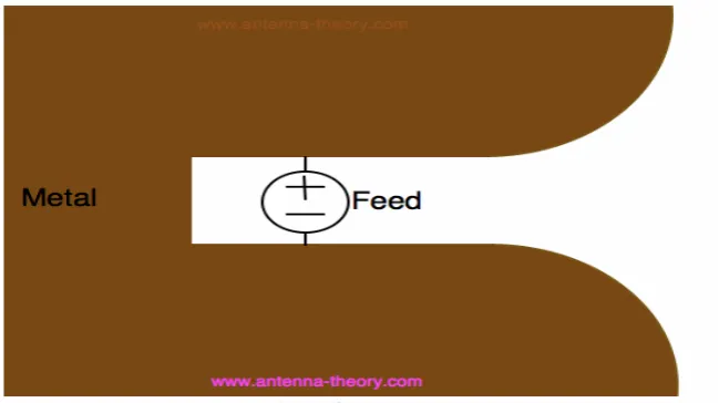
1.1Introduction
[image:14.595.151.476.509.691.2]Vivaldi antenna is simple planar that are very broadband. The basic shape of Vivaldi antenna can be seen in Figure 1.1 and Figure 1.2 The antenna feed connecting two symmetric of a planar metallic antenna. Sometimes Vivaldi antenna referred to as the Vivaldi notch antenna, and also known as the tapered slot antenna (TSA), is easy to fabricate on a circuit board, and can provide ultra-wide bandwidth.
2
1.1.1. Vivaldi Antenna Design
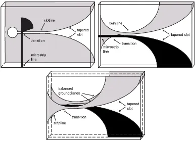
There are three fundamental types of Vivaldi antenna:
a) Tapered slot Vivaldi antenna
Tapered slot Vivaldi antenna is the original design introduced by Gibson in 1979[8]. It’s basically a flared slotline, fabricated on a single metallization layer and supported by a substrate dielectric. The taper profile is exponentially curved, creating smooth transition from the slot line to the open space. This structure introduces two limits for the operational band- width of the antenna, following the rule for slotline radiation [6].
b) Antipodal Vivaldi Antenna
Antipodal Vivaldi antenna was investigated by W. Nester in 1985 and E. Gazit in 1988 [7] as a solution of the feeding problems associated with Gibson’s original design. In the antipodal configuration, antenna is created on a dielectric substrate with two-sided metallization. Main disadvantage of the antipodal configuration is cross-polarization, observed especially for higher frequencies. This is caused by the skew of the slot fields. The skew is changing along the length of the taper, being highest in the closed end of the antenna, where high frequencies are being radiated; while at the open end is usually negligible, depending on the substrate thickness [6].
c) Balanced Antipodal Vivaldi Antenna
3
[image:16.595.131.517.202.481.2]antenna feed, which could occur in case of open feed lines of the antipodal and tapered slot Vivaldi. This solution suppresses perturbances of the radiation pattern caused by the open feed lines. There are also some disadvantages of the balanced design. Naturally, the construction of such antenna is more complicated due to the triplate structure, preventing it from fabrication in some lab environments [6].
Figure 1.2: Tapered slot Vivaldi antenna, Antipodal Vivaldi Antenna, Balanced Antipodal Vivaldi Antenna
4
At different frequencies, different parts of the antenna radiate, while the radiating part is constant in wavelength. Thus the antenna theoretically has an infinite bandwidth of operation and can thus be termed frequency independent. As the wavelength varies, radiation occurs from a different section which is scaled in size in proportion to the wavelength and has the same relative shape. This translates into an antenna with very large bandwidth [13].
Vivaldi antennas provide medium gain depending on the length of the taper and the shape of the curvature. The gain also changes with frequency, with values ranging typically from 4 dBi to 8 dBi. Because of the exponential shape of the tapered radiating structure, antenna maintains approximately constant beamwidth over the range of operating frequencies.From the time-domain point of view, the principle of radiation through the tapered slot is lacking any resonant parts, which results in very low distortion of radiated pulses.This aspect, together with large bandwidth of the antenna, makes Vivaldi very good UWB radiator in cases when directional antenna is desired [6].
1.1.2. Transmission Line
A transmission line is a device designed to guide electrical energy from one point to another. Transmission line is use to transfer the energy output of the transmitter to the antenna with the least possible power lost [10]. Usually antenna is located far away from the transmitter so the transmission is used to connect the transmitter and antenna. The transmission line must be perfectly matched to achieving a good transmission. Mismatch will occur when a transmission line is not properly terminated at the receiver end and some of energy wills reflect back into transmission line from load. The amount of incident energy that is reflected is represent by the reflection coefficient, r. The magnitude of reflection coefficient can vary from 0 to 1[10].
5
curvature of the radiating structure ensures theoretically unlimited bandwidth, which is, in practice, constrained by the taper dimensions, the slot line width and the transition from the feed line. The limitation introduced by transition was later partially overcome in the antipodal design investigated.
1.1.3. Parameters of Antenna
a) Radiation Pattern
[image:18.595.177.462.445.718.2]An antenna radiation pattern or antenna pattern is defined as a mathematical function or a graphical representation of the radiation properties of the antenna as a function of space coordinates. There can be field patterns (magnitude of the electric or magnetic field) or power patterns (square of the magnitude of the electric or magnetic field).Often normalized with respect to their maximum value. The power pattern is usually plotted on a logarithmic scale or more commonly in decibels (dB) [17].
6
A radiation lobe is a portion of the radiation pattern bounded by regions of relatively weak radiation intensity.
• Main lobe • Minor lobes • Side lobes • Back lobes
b) Beamwidth
The beamwidth of an antenna is a very important figure of merit and often is used as a trade-off between it and the side lobe level; that is, as the beamwidth decreases, the side lobe increases and vice versa. The beamwidth of the antenna is also used to describe the resolution capabilities of the antenna to distinguish between two adjacent radiating sources or radar targets [17].
c) VSWR and Return loss
The parameter VSWR is a measure that numerically describes how well the antenna is impedance matched to the radio or transmission line it is connected to. VSWR (Voltage Standing Wave Ratio) is function of the reflection coefficient, r, which describes the reflected from the antenna. VSWR is the ratio of the maximum to minimum values of the standing wave pattern that is created when signal is reflected on a transmission line. VSWR is a voltage standing wave ratio [17]. The voltage standing wave ratio is a measure of how well a load is impedance-matched to a source. It is always express as a ratio with 1 in the denominator (2:1, 3:1, etc). The lowest value of VSWR is 1 and it means when VSWR equal to 1, all the power is transfer from source to load. If the VSWR for antenna is below than 2, it show the performance of antenna is satisfactory in term of VSWR
= 1+|�|
7
Reflection coefficient is also known as S11 or return loss. VSWR is always a real number and positive numbers for antenna. The smaller VSWR value, the better the antenna is matched to the transmission line and the more power is delivered to the antenna. The minimum VSWR is 1.0 where no power is reflected from the antenna, which is ideal.
d) Directivity
Directivity is defined as ratio of radiation intensity, in a given direction, to the radiation intensity that would be obtained if the power accepted by the antenna where radiating isotropic ally [19]. Directivity is a fundamental antenna parameter. It is measure of how directional an antenna’s radiation pattern. The directivity of antenna can be calculate using Poynting Vector, P, that show the average real power per unit area radiated by an antenna in free space. The directivity equation is given below [20]:
=���
� (1.2)
| � = 10���1����
� (1.3)
�� = 4����2 (1.4)
Pa is total power radiated by antenna and r is distance between the two
antennas. The antenna gain takes into account loss so the gain of an antenna will always be less than the directivity.
e) Gain
8
� =�� (1.5)
Theoretically, gain of antenna always greater than 0dB and can be high as 40-50dB for the very large antenna like dish antenna [17]. If the input power appeared as radiated power, directivity is equal to gain [18].
f) Radiation efficiency
Radiation efficiency is the ration of total power radiate by an antenna to the net power accepted by the antenna from the connected transmitter [19]. The equation of efficiency of antenna is given below:
=��� ����
� =
��2 ( �+ �)�2 =
�
( �+ �)=
1
1+ �/ � (1.6)
RL is loss resistance which corresponds to the loss of antenna and Rr
is the radiation resistance. For good antenna efficiency, radiation resistance must be big and loss resistance to be as small as possible.
1.1.4 Graphene
Graphene is the name given to a flat monolayer of carbon atoms tightly packed into a two dimensional (2D) honeycomb lattice, and is a basic building block for graphitic materials of all other dimensionalities. Graphene is a sheet of carbon just one atom thick, in a honeycomb structure, and it has many desirable electronic properties. Electrons move through graphene with virtually no resistance—50 to 500 times faster than they do in silicon [21].
9
respect to the formation of curved structures such as soot, fullerenes and nanotubes. Suddenly, the vintage model turned into reality, when free-standing graphene was unexpectedly found three years ago and especially when the follow-up experiments confirmed that its charge carriers were indeed mass-less Dirac fermions. So, the graphene “gold rush” has begun [14].
1.2 Objectives
For this project, there are three main objectives that were listed:
To analyze the optimized design Vivaldi antenna with different material (graphene and copper).
To simulate the Vivaldi antenna using CST Studio Suite software
To analyze performance of antenna on return loss, gain, efficiency and directivity
1.3 Problem Statement
10
1.4 Scope
CHAPTER 2
LITERATURE REVIEW
2.1Graphene
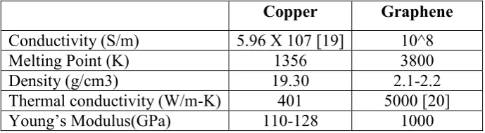
[image:24.595.147.492.526.621.2]The use of graphene in built of antenna could bring significant benefit such as extreme miniaturization, monolithic integration with graphene RF nanoelectronics, efficient dynamic tuning and even transparency and mechanical flexibility [1]. This project were about to study the Vivaldi antenna and improve the directivity or gain of this antenna. Graphene has a big potential replaced the copper in scope of antenna. Table below shows the comparison between copper and graphene.
Copper Graphene
Conductivity (S/m) 5.96 X 10⁷ [19] 10^8
Melting Point (K) 1356 3800
Density (g/cm3) 19.30 2.1-2.2
Thermal conductivity (W/m-K) 401 5000 [20]
Young’s Modulus(GPa) 110-128 1000
![Figure 1.3: Radiation pattern lobes [17].](https://thumb-ap.123doks.com/thumbv2/123dok/521296.59821/18.595.177.462.445.718/figure-radiation-pattern-lobes.webp)