Development of Glove Controlled Prosthetic Hand
KEW MUN YEW
This thesis is submitted in partial fulfillmentof the requirement for the Bachelor Degree of Electronic Engineering (Computer Engineering)
Faculty of Electronic and Computer Engineering Universiti Teknikal Malaysia Melaka
ACKNOWLEDGEMENT
First of all, I would like to sincerely thank to my supervisor, Dr. Soo Yew Guan given enthusiasm and guidance throughout the project. Ever since his supervision, I obtained a lot of idea, knowledge and support regarding this project from him.
ABSTRACT
ABSTRAK
CONTENTS
CHAPTER SUBJECT PAGE
TITLE i
ACKNOWLEDGEMENT ii
ABSTRACT iii
ABSTRAK iv
CONTENTS v
LIST OF TABLES viii
LIST OF FIGURES ix
LIST OF ABBREVIATIONS xi
CHAPTER I INTRODUCTION
1.1 Background of Project 1
1.2 Objectives 2
1.3 Scope of Project 2
CHAPTER II LITERATURE REVIEW
2.1 Prosthesis 4
2.2 Actuators 5
2.2.1 Pneumatic artificial muscles 5
2.2.2 Sensing 6
2.2.3 Servomotor 7
2.2.4 Communication 8
2.3 Existing Robot Hand 9
2.3.1 Michelangelo Hand 9
2.3.2 Mechatronic Design of Innovative
Fingers for Anthropomorphic Hands 11 2.3.3 Pinching at finger tips by
humanoid robot hand 12
CHAPTER III METHODOLOGY
3.1 Development Process 14
3.1.1 Phase 1 – Mechanical Design Process 14 3.1.2 Phase 2 – Electronic Control
Development Process 14 3.1.3 Phase 3 – Software Development Process 14
3.2 Electronic Control System 15
3.3 Project Implementation 15
CHAPTER IV HARDWARE DEVELOPMENT
4.1 Mechanical Design 20
4.1.1 Prosthetic Hand Framework 20
4.1.2 String Pulling Method 22
4.1.3 The Servomotor 23
4.1.4 Data Glove Design 24
CHAPTER V SOFTWARE DEVELOPMENT
5.1 Software Design 27
5.2 PIC Programming 28
5.3 Pulse Width Modulation (PWM) 30
5.4 PIC Timers 31
5.4.1 Timer 0 32
5.4.2 Timer 1 34
5.4.3 Timer 2 37
5.4.4 Timer 3 40
5.5 MPLAB IDE 41 43
CHAPTER VI RESULT AND ANALYSIS
6.1 Motor and Finger Force Analysis 45
6.1.1 Motor Torque and Speed 45
6.2 Program debugging 46
6.3 Data glove Controller 48
6.4 Prosthetic Hand’s fingers Movement 49
CHAPTER VII CONCLUSION AND RECOMMENDATION
7.1 Conclusion 50
7.2 Recommendation 52
REFERENCE 52
APPENDIX A 53
LIST OF TABLES
TABLE NUMBER TITLE PAGE
4.1 Prosthetic hand mechanism specification 30
LIST OF FIGURES
FIGURE NUMBER TITLE PAGE
2.1 Agonist and Antagonist 15
2.2 Connecter of the servo motor. 17
2.3 Michelangelo Hand. 20
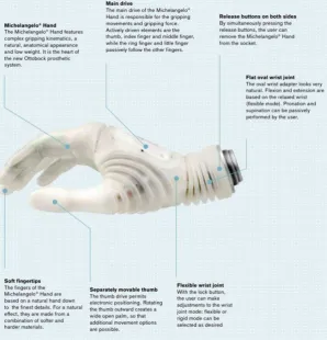
2.4 Description of Michelangelo Hand 20
2.5 CAD representation of the finger under development 21
2.6 Structural scheme of the endoskeleton. 21
2.7 Mechanism of Finger. 23
2.8 Inside mechanism in a palm 23
3.1 Theoretical design of the finger 25
3.2 Electronic Control Block Diagram. 26
3.3 PSM 1 Planning. 27
3.4 PSM 2 Planning. 28
4.1 Prosthetic Hand dimension and orientation. 31
4.2 Strings Tie Method for Servomotor and Finger. 31
4.3 Strings Tie Method for Finger. 32
4.4 First prototype built using zipper chain. 32
4.5 Finger built and tied with guitar string. 32
4.6 Second prototype for one finger. 32
4.7 Third prototype consists of 5 fingers and no cover. 32
4.8 Final Prosthetic hand with cover. 33
4.9 The basic idea layout of robot’s finger. 34
4.10 The configuration of String pulling. 34
4.11 The dimension of Servomotor. 35
4.12 Flex sensor. 36
4.13 Glove with flex sensors. 36
4.14 Portable power bank that used in this project. 37
5.1 Prosthetic hand program flowchart. 41 5.2 Servomotor pulse width value and its related angles. 42
5.3 PIC 18F4550 Timers Diagram. 43
6.1 Prototype of prosthetic hand 56
6.2 The self-made PIC Boot loader 58
6.3 The MPLAB IDE programming, Simulating and debugging platform. 58
6.4 The USB Boot loader debugging platform. 59
6.5 Process of one finger debugging its position locomotion. 59
6.6 Data glove controller. 60
LIST OF ABBREVIATIONS
PIC - Peripheral Interface Controller PCB - Printed Circuit Board
PAMs - Pneumatic Artificial Muscles PWM - Pulse-Width Modulation
PC - Personal Computer
CHAPTER I
INTRODUCTION
1.1 Background of Project
Prosthetic hand is a part of robot arm, and it is important part for a humanoid robot. Typical applications of robot hand include welding, painting, ironing, assembly, pick and place, packaging and testing, all accomplished with high endurance, speed, and precision. It is easy to found a robot hand in now a day industrial for instead of human hand to do the dangerous job and precision job. Industrial robot hands are used in the production process and the transportation process for quality control and carrying the heavy stuff.
Prosthetic hand may be used in place of people demolition bomb to reduce casualties. Astronauts will allow the robot to check out the surrounding areas, to ensure the safety of the space. In addition, the prosthetic hand is also widely used for helping doctor in medical surgery patients. This requires very precise technology to avoid the mistake.
1.2 Objectives
The objectives of the project are as follows:
The aims of this work is to develop a prosthetic hand that is able to:
o Pick up or handle small to medium sized objects o Grasping roll material
o Perform like a humanoid robot hand o Control using data glove controller
o User able control the prosthetic hand without any training
1.3 Scope of Project
The system consists of a mechanical design, electronic hardware, and software. The works undertaken in the project are limited to the mechanical part, electronic control, and software development.
For the mechanical part: The prosthetic hand includes a finger skeleton design, motor, and caster mounting. String is mounted at the shaft of servo motor to pull the finger. This prosthetic finger is designed to operate in 5 degree of freedom. The data glove design includes the sensor in each the finger by using flex sensor.
Electronic control: Choosing PIC microcontroller as the main brain of the control system. Input and feedback control using same flex sensor. The servo controller can generate the servo pulse from 0.5ms to 2.5ms when it received the signal from the PIC microcontroller.
1.4 Work Contribution
I have developed a five fingers prosthetic hand that has a 15 degree of freedom. Each sector of the finger was tied with a chain system that powered by the servo motor. The prosthetic hand was capable to pick up small to medium size object and sphere shape object. The major contributions of this work are:
Built a robot index finger which is manipulated by the servo motor.
Built the prosthetic hand other 5 fingers and successfully manipulated them by the servo motors.
Combined all the fingers to develop prosthetic hand, which was controlled and manipulated by using a PIC microcontroller.
I have successfully controlled the prosthetic hand by using a data glove; the output of the data glove is directly proportional to the input for the PIC microcontroller. The microcontroller generated the PWM signals which were used by the servo controller to control the shaft position of the servo motor. I have successfully tested our prosthetic hand capability to pick up small and
CHAPTER II
LITERATURE REVIEW
2.1 Prosthesis
In the last thirty years several examples of robotic hands have been developed by research or industry, some designed to mimic the human hand in its manipulation dexterity and functionality, some aimed at achieving better anthropomorphism and cosmetic appearance. Great research effort has been focused on the design of both articulated end-effectors and smart dexterous anthropomorphic hands, for humanoid robotics and prosthetics.
2.2 Actuators
Actuators are the motors responsible for motion in the robot. A mechanism or robot are constructed in such a way that they mimic the animal or human body, so the actuators are perform like a muscles and joints but with a different structure. To achieve the effect motion of the robot, robots normally use mainly rotary actuator. The common actuator is electric, pneumatic, hydraulic, piezoelectric or ultrasonic control.
2.2.1 Pneumatic artificial muscles
[image:19.595.179.445.463.597.2]Pneumatic artificial muscles (PAMs) are contractile or extensional devices operated by pressurized air. Similarly to human muscles, PAMs are usually grouped in pairs (Figure 2.1) one agonist and one antagonist.
Figure 2.1: Agonist and Antagonist
and thereby exerts a pulling force on its load. The force and motion thus generated by this type of actuator are linear and unidirectional. This contractile operation distinguishes the PAM from bellows, which extend upon inflation.
Although this type of actuator is very suitable to use as the muscle of a humanoid robot, it is hard to find in Malaysia market, so this actuator will not been used in this project.
2.2.2 Sensing
Sensor is a device that measures a physical quantity and converts it into a signal which can be read by an observer or by an instrument. The sensor is responsive to changes in the quantity to be measured, for example, temperature, position, or chemical concentration. The transducer converts such measurements into electrical signals which usually amplified, can be fed to instruments for the readout, recording, or control of the measured quantities. Sensors and transducers can operate at locations remote from the observer and in environments unsuitable or impractical for humans
2.2.3 Servo Motor
A servo motor is a generic term used for and automatic control system. The Servo is an automatic device which uses error-sensing feedback to correct the performance of a mechanism. The term correctly applies only to systems where the feedback or error-correction signals help control mechanical position or other parameters. In practical terms, that means a mechanism that you can set and forget, and which adjusts itself during continued operation through feedback.
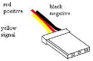
[image:21.595.221.376.402.504.2]There are numerous types of servos but they differ in their precision, speed, and strength. The connection of these servos are same, is controlled by three wires (see figure 2.2) which is negative, positive and signal. Roughly 6VDC to power the servo motor and a PWM pulse stream to control position.
Figure 2.2: Connecter of the servo motor
2.2.4 Communication
In my project, the communication between microcontroller and microcontroller with the computer is needed and the USB PIC Boot loader will be used. USB PIC Boot loader is a resident boot loader for PIC18 series of Enhanced Flash USB Microcontrollers. It allows user to program application hex into the chip using the standard USB connectivity of your device.
USB PIC Boot loader code is write-protected and cannot be overwritten by firmware. Firmware update or user mode is selected by SW and/or HW switch. Boot loader runs at the boot time (when the processor has just been reset) and is capable of loading a complete application program into a processors memory.
With the USB PIC Boot loader loaded, there are two distinct modes of operation: firmware update mode and Application mode. USB PIC Boot loader uses the EEPROM mark and/or hardware switch to determine which mode to run in.
Firmware Update Mode.
In firmware update mode USB PIC Boot loader utilizes USB connection of Microchip PIC Microcontroller to communicate with PC and load the new application code. Once the programming is done, the USB PIC Boot loader switches to Application mode, the processor is reset and begins running the newly loaded code.
Application mode.
2.3 Existing Prosthetic Hand
Prosthetic hands have not been widely sold in the market. So this literature is based on the existing prosthetic hand build by individual person or University research. There is one of company got sold the robot hand in this world which is American company Advanced Arm Dynamics. This company manufactured a product name Michelangelo Hand show in Figure 2.3.
2.3.1 Michelangelo Hand
The Michelangelo Hand is robotic hand prosthesis developed by Otto Bock and the American company Advanced Arm Dynamics. The fully articulated hand is the first prosthesis to feature an electronically actuated thumb which mimics natural human hand movements. It can be used for a variety of delicate everyday tasks, and has been in use by military and civilian amputees in the United States and United Kingdom since 2011.
Figure 2.3: Michelangelo Hand
[image:24.595.149.448.429.739.2]