i
PC-BASED MOTOR SPEED CONTROL
SUN JOE HIM
This report is submitted in partial fulfillment of the requirements for the award of Bachelor of Electronic Engineering (Industrial Electronics) with Honours
Faculty of Electronic and Computer Engineering Universiti Teknikal Malaysia Melaka
ii
UNIVERSTI TEKNIKAL MALAYSIA MELAKA
FAKULTI KEJURUTERAAN ELEKTRONIK DAN KEJURUTERAAN KOMPUTER
BORANG PENGESAHAN STATUS LAPORAN PROJEK SARJANA MUDA II
Tajuk Projek : PC-BASED MOTOR SPEED CONTROL
Sesi
Pengajian : 2008/2009
Saya SUN JOE HIM mengaku membenarkan Laporan Projek Sarjana Muda ini disimpan di Perpustakaan dengan syarat-syarat kegunaan seperti berikut:
1. Laporan adalah hakmilik Universiti Teknikal Malaysia Melaka.
2. Perpustakaan dibenarkan membuat salinan untuk tujuan pengajian sahaja.
3. Perpustakaan dibenarkan membuat salinan laporan ini sebagai bahan pertukaran antara
institusi pengajian tinggi.
4. Sila tandakan ( √ ) :
SULIT*
(Mengandungi maklumat yang berdarjah keselamatan atau kepentingan Malaysia seperti yang termaktub di dalam AKTA RAHSIA RASMI 1972)
TERHAD* (Mengandungi maklumat terhad yang telah ditentukan oleh organisasi/badan di mana penyelidikan dijalankan)
TIDAK TERHAD
Disahkan oleh:
__________________________ ___________________________________ (TANDATANGAN PENULIS) (COP DAN TANDATANGAN PENYELIA)
Alamat Tetap: 64, LEBUH BERCHAM TIMUR 1/17, TAMAN RIMA GAMELAN, 31400 IPOH,
PERAK, MALAYSIA.
Tarikh: 30 APRIL 2009 Tarikh: 30 APRIL 2009
iii
“I hereby declared this report is result of my own effort except for works that have been cited clearly in the references.”
Signature : ……….
iv
“I hereby declare that I have read this report and in my opinion this report is sufficient in terms of the scope and quality for the award of Bachelor of Electronic
Engineering (Industrial Electronics) with Honours.”
Signature : ……….…
Supervisor’s Name : YUSMARNITA BINTI YUSOP
v
vi
ACKNOWLEGEMENT
I wish to express sincere appreciation to Universiti Teknikal Malaysia Melaka (UTeM) for giving me a chance to further my study on Bachelor of Degree in Industrial Electronics in Faculty of Electronics and Computer Engineering (FKEKK).
Despite of that, I would take this opportunity to express my profoundest gratitude and deepest regards to all those who gave me the possibility to successfully complete this PSM. I am deeply indebted to my Project Supervisor Puan Yusmarnita Binti Yusop and I wish to express a million thanks for her exemplary guidance, monitoring and constant encouragement throughout the development of the project.
I would like to express my gratitude and appreciation to the following people for their essential helps, guidance and supports in making my PSM’s project more successful. They are Mr. Khoo Boo Hock, Mr. James Phang Joon Shin, Mr. William Tam, Mr. Ng Thian Loon, NI supporter and to all my lecturers, panels, technicians, course mates and friends who are directly or indirectly involved in my PSM’s project.
vii
ABSTRACT
viii
ABSTRAK
Motor elektrik telah digunakan secara meluas untuk pelbagai aplikasi semenjak revolusi perindustrian. Kelajuan dan arah pusingan motor adalah bergantung kepada aplikasinya. Kaedah yang sedia ada memerlukan penyelarasan pada perintang boleh laras untuk mengawal kelajuan motor. Namun demikian, pendekatan sebegini akan menyebabkan kehilangan kuasa yang tinggi dan menunjukkan sistem yang digunakan tidak efisien. Walaupun kaedah kawalan PWM telah biasa digunakan untuk mengatasi kelemahan ini, tetapi isyarat kawalan yang terhasil dan kelajuan pusingan yang sebenar tidak dapat dipaparkan serta dikawal. Justeru itu, kebolehharapan, keberkesanan serta kejituan teknik isyarat PWM masih tidak jelas. Projek ini bertujuan untuk membangunkan suatu sistem kawalan kelajuan motor AT secara berkomputer. Sistem yang berjaya dibangunkan boleh menjana isyarat PWM dengan menggunakan perisian NI LabVIEW dan peranti NI DAQ (USB-6221) bagi membolehkan pengawasan secara digital dan mengawal kitar duti
ix
TABLE OF CONTENTS
CHAPTER TITLE PAGE
TITLE OF THE PROJECT i
BORANG PENGESAHAN STATUS LAPORAN ii
STUDENT’S DECLARATION iii
SUPERVISOR’S DECLARATION iv
DEDICATION v
ACKNOWLEDGEMENT vi
ABSTRACT vii
ABSTRAK viii
TABLE OF CONTENT ix
LIST OF TABLES xi
LIST OF FIGURES xii
LIST OF ABBREVIATION xiv
LIST OF APPENDIXES xv
I INTRODUCTION 1
1.1 Introduction to PC-Based Control System 1
a) DC Motor Block Diagram 3
b) AC Motor Block Diagram 3
1.2 Project Objectives 4
1.3 Problem Statement 4
a) DC Motor Closed-Loop System 4 b) Hardware Controller and the Software 5 c) PC-Based System Controlling and
Monitoring Method 5
x
1.4 Scope of Work 6
1.5 Report Structure 6
II LITERATURE REVIEW 8
2.1 Introduction of Literature Review 8 2.2 National Instrument LabVIEW Software 9
a) Graphical Programming 9
b) Connectivity and Instrument Control 11 c) Reduces Cost and Preserves Investment 12
d) Multiple Platforms 12
e) Analysis Capabilities 13
f) Visualization Capabilities 13 g) Flexibility and Scalability 13
h) Research and Design 14
i) Development Test and Validation 14
j) Manufacturing Test 14
k) Manufacturing 15
l) Data Acquisition 15
2.3 Introduction of PID Controller 17
a) Control Loop Basics 18
b) PID Controller Theory 20
c) Summary 25
d) Loop Tuning 25
e) Manual Tuning 27
f) Ziegler–Nichols Method 27
g) PID Tuning Software 28
h) Modifications to the PID Algorithm 29
i) Limitations of PID Control 30
j) Cascade Control 32
k) Physical Implementation of PID Control 32
l) NI LabVIEW and PID 33
xi a) Three-Phase AC Induction Motor 35
2.5 Introduction of Variable Frequency Inverter 37
a) VFD System Description 38
III PROJECT METHODOLOGY 42
3.1 Research Methodology 42
3.2 Software Development for DC and AC Motor 44 3.3 Hardware Development for AC Motor 45 3.4 Flowchart of the DC Motor Upgrading 47 3.5 Flowchart of the AC Motor Developing 49 3.6 Interfacing with Hardware and Software
using DAQ Device 50
IV RESULT 51
4.1 Introduction of Result and Analysis 51 4.2 Hardware Development – Speed Detector Circuit 52
4.3 DC Motor Part 54
a) Front Panel of DC Motor – Original Program 54 b) Block Diagram – Original Program 55 c) Input without PID Controller 55
d) Result of Original Program 56
e) Added PID Controller Program 57 f) Block Diagram for Motor Direction 61 g) Result after Added PID Controller 62 h) Discussion of DC Motor Part 63
4.4 AC Motor Part 64
a) Front Panel of AC Motor 64
b) Block Diagram – Analog and Digital
Signal Generator 64
xii d) Result Analysis for AC Motor 66
e) Data Collected 69
4.5 Discussion 72
V CONCLUSION AND SUGGESTION 73
5.1 Conclusion 73
5.2 Suggestions 74
xiii
LIST OF TABLES
NO TITLE PAGE
2.1 Choosing a Tuning Method 26
2.2 Effects of Increasing Parameters 27
2.3 Ziegler–Nichols Method 28
4.1 Types of Rules 59
xiv
LIST OF FIGURES
NO TITLE PAGE
1.1 DC Motor Closed-Loop System 3
1.2 AC Motor Block Diagram 3
2.1 NI LabVIEW Virtual Instrument Block Diagram 10 2.2 NI LabVIEW Virtual Instrument Front Panel 11
2.3 NI-USB-6221 DAQ Device 16
2.4 A Block Diagram of a PID Controller 18
2.5 Plot of PV vs. Time, for Three Values of Kp
(Ki and Kd Held Constant) 21
2.6 Plot of PV vs. Time, for Three Values of Ki
(Kp and Kd Held Constant) 22
2.7 Plot of PV vs. Time, for Three Values of Kd
(Kp and Ki Held Constant) 24
2.8 VIs from the PID Controls Palette of LabVIEW 33 2.9 Advanced VIs from the PID Controls Palette of LabVIEW 33 2.10 A Typical LabVIEW VI Showing PID Control with a Plug-In
NI Data Acquisition Device 34
2.11 Disassembled 250W Motor from a Washing Machine 35 2.12 Three Phase AC Induction Motors Rated 1 Hp (746 W) 36
2.13 Small Variable Frequency Inverter 37
2.14 VFD System 38
2.15 PWM VFD Diagram 39
2.16 PWM VFD Output Voltage Waveform 40
3.1 Block Diagram of DC Motor 43
xv 3.3 The Flows Used in Creating the LabVIEW Block Diagram 44
3.4 Single Sample Analog Output Programming Flowchart 45 3.5 The Method Used for the Circuit Design and Implementation 45
3.6 Flowchart of the DC Motor Upgrading 47
3.7 Flowchart of the AC Motor Main Control Using LabVIEW 49
4.1 Speed Detector Circuit 52
4.2 Front Panel of Original Program 54
4.3 Block Diagram of Original Program 55
4.4 Front Panel Duty Cycle Input 55
4.5 Block Diagram Duty Cycle Input 55
4.6 Output Amplitude Not Constant from DC Motor
without PID Controller 56
4.7 Front Panel after Added PID Controller 57 4.8 Block Diagram after Added PID Controller 58
4.9 Front Panel PID Gain Input 58
4.10 Block Diagram PID Gain Inputs 58
4.11 Front Panel - Table Array to Type in Transfer Function 60 4.12 Block Diagram to Construct Transfer Function 60
4.13 Block Diagram for DC Motor Direction 61
4.14 Front Panel for AC Motor Part 64
4.15 Variable Analog Voltage Output and 5V Digital Signal Output 64
4.16 Signal Detector Block 65
4.17 1V Input to VFD 66
4.18 2V Input to VFD 66
4.19 3V Input to VFD 66
4.20 4V Input to VFD 67
4.21 5V Input to VFD 67
4.22 6V Input to VFD 67
4.23 7V Input to VFD 68
4.24 8V Input to VFD 68
4.25 9V Input to VFD 68
4.26 10V Input to VFD 69
xvi
LIST OF ABBREVIATION
PC - Personal Computer DC - Direct Current AC - Alternative Current PWM - Pulse Width Modulation DAQ - Data Acquisition VI - Virtual Instrument
LabVIEW - Laboratory Virtual Instrument Engineering Workbench NI - National Instrument
TC/IP - Transmission Control Protocol / Internet Protocol I/O - Input/ Output
GPIB - General Purpose Interface Bus R&D - Research and Development PLC - Programmable Logic Controller
BASIC - Beginner's All-purpose Symbolic Instruction Code USB - Universal Serial Bus
LED - Light Emitting Diode
RFI - Radio Frequency Interference Op-Amp - Operational Amplifier
xvii
LIST OF APPENDIXES
NO TITLE PAGE
A Datasheet NI USB-6221 76
B Datasheet VFD 77
C Hardware Completed Prototype 78
D Instruction 79
1
CHAPTER I
INTRODUCTION
In this chapter, discusses regarding the introduction of PC-based monitoring and describing the technique used to control the speed of the DC and AC Motor. The block diagram gave the general ideas on this project. In addition, objectives, problem statement of the project and the report structure is included as well.
1.1 Introduction to PC-Based Control System
The beginning of a sweeping change is upon the control and instrumentation world. With the availability of robust hardware, open technology and real-time, Windows-based operating systems, PC-based control is emerging as a new control paradigm for increasing manufacturing productivity. PC-based control offers open and more intuitive traditional solutions at a lower total system cost and easier migration to future technologies. Easier development, integration, portability, and access ensure a flexible and efficient solution.
2 benefits and challenges accrued when committing to this next level of control technology.
Manufacturers around the world look to PCs to play a bigger role in their control systems. PCs are already an accepted platform for system supervisory control, monitoring and reporting, as well as off-line data management and analysis. Manufacturers have already realized the flexibility of the PC and the easy-to-use open architecture of Windows-based software applications for the manufacturing environment.
In this project, the DC and AC motor’s speed are controlled by using the LabVIEW 8.5 software package from the National Instrument (NI) by using PC. There are many methods that have been used to control the DC and AC motor’s speed, the conventional method is by adjusting the supply voltage of the motor but this method is inefficient because the power losses is high. So, to solve this problem, Pulse Width Modulation (PWM) technique had been used to make the control of DC and AC motor are more efficient, it is called the hardware controlling technique. The PWM signal can easily be generated with the combination of LabVIEW 8.5 software and data acquisition device (DAQ).
For the DC motor part, it is PC-based monitoring and controlling for motors speed control. It is an opened-loop system, it only can achieve up to control the speed of DC motor, detecting the speed of motor, and switching the direction of motor. In order to improve the current project, closed-loop DC motor control system will be implementing to correct the error of the motor’s speed and maintaining the speed.
3
a) DC Motor Block Diagram
[image:20.595.156.475.119.192.2]
Figure 1.1: DC Motor Closed-Loop System
The general idea of the closed-loop system can be described based in Figure 1.1. This idea is closed-loop system with PID controller. Initially of the system need to set duty cycle as a Set Point, the value must be permanent and cannot be vary. Then the next block is PID Controller, the PID Controller is construct as parallel type. It need set value of the Ziegler-Nichols Rule as tuning rule. Output of PID Controller connected to Process block, then the output of PWM signal as a reference point feedback to summing junction.
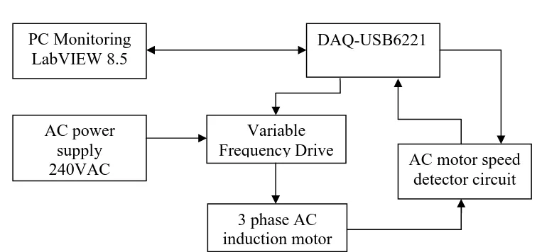
b) AC Motor Block Diagram
Figure 1.2: AC Motor Block Diagram
Set point PID Control Process
PC Monitoring LabVIEW 8.5
DAQ-USB6221
Variable Frequency Drive
AC motor speed detector circuit AC power
supply 240VAC
[image:20.595.149.527.495.673.2]4 The general idea of the project can be described based in Figure 1.2. A PC with the installed NI LabVIEW 8.5 software for monitoring and controlling is used to interface with the AC motor speed controller and speed detector circuit. The NI USB-6221 DAQ device supplied 5 Volt to the speed detection circuit as a power supply. The variable output voltage can be generated with the combination of the PC and DAQ device. Variable output voltage is used to vary the speed of the AC motor. The speed in RPM can be measured and displayed on the Virtual Instrument front panel.
1.2 Project Objectives
There are several objectives that need to be achieved at the end of PSM. The objectives are listed as below:
i. To upgrade the existing project from DC motor opened-loop system to close system with PID control.
ii. To develop the interactive front panel that can monitor and control both DC and AC motor.
iii. To interface the DC&AC motor with the PC-based system by using LabVIEW 8.5 through DAQ-USB6221.
iv. To ease the users in controlling or monitoring the speed of DC and AC motor by using the PC instead of physical controlling method.
1.3 Problem Statement
a) DC Motor Closed-Loop System
5 open loop system cannot feedback the “speed” signal to compare with set point. Due to this advantage, PID control method is applied to design the close loop system in order to overcome the problem. From the PID controller, need to set Kp, Td and Ti value to tune the graph output signal to be smooth.
b) Hardware Controller and the Software
By using the DAQ-USB6221 device, the sampling process can be quickly done right after the signal is sent from the DC&AC motor. The sampled result can be shown on the LabVIEW front panel in the rapid of time instead of by using the manual sketching and calculation.
c) PC-Based System Controlling and Monitoring Method
The accuracy and the safety level of controlling the speed of DC&AC motor physically are lower than controlling the speed by using PC. The errors produced will definitely very small if the PC-Based system is used.
d) Reason for Select LabVIEW Software
6
1.4 Scope of Work
The scope of work in this project is started as given:
i. LabVIEW graphical programming software is selected to create the interactive of the Virtual Instrument which is called Front Panel where create the screen should consist of push buttons, meters, graphs, and other controls and indicators.
ii. The design of PID compensator is introduced in this DC motor upgrading section. The PID compensator is probably the most commonly used compensator in feedback control systems. With the compensator input and the output, the PID compensator is defined by the equation.
iii. Data acquisition device is used to obtain the signal from the AC motor. Data is entered via a mouse or keyboard; the results are then viewed on the computer screen through the indicator i.e. the meter and graphs.
1.5 Report Structure
This thesis is a documented report of the ideas generated, the theories and concepts applied, the activities performed and the final product of this project produced. The thesis consists of five chapters and each chapter is described as below:
Chapter 1, the introduction of PC-based monitoring and describing the technique used to control the speed of the DC and AC Motor. The block diagram gave the general ideas on this project. In addition, objectives, problem statement of the project and the report structure is included as well.
Chapter 2, the background study of the project along with the literature review is performed and documented about the theoretical concept applied in completing the project. Background studies on the PID controller and AC motor operation method are stated throughout this project.
7 Chapter 3 is the introduction of methodology for the project, design flow and construction of the project. Brief description is given about each procedure in the completion of the project.
Chapter 4 shows overall result and discussion of the result as well as the comparison with the conventional method. Hardware prototyping and the developed LabVIEW Virtual Instrument front panels, the created LabVIEW block diagrams about the project are shown in order to strengthen the result.
Chapter 5 is the final part of the thesis which concludes the Final Year Project. This chapter includes the application of the project and the recommendation that can be implemented for future references.