Design Aspects of WINDS
Ground Facility for
Malaysia
Zulfiqar
AliLeghari, Abdul Rani Bin Othman,,
Imran B. Mohd Ibrahim, Maisarah Binti AbuFaculty Electronic& ComputerEngineering
Kolej
UniversitiTeknikalKebangsaan 1200 AyerKeroh, 75450 Melaka, Malaysia,Tel. 06-5552096, H/p. 017-3602663
zulfiqar(&kutkm.edum
Abstract Internet access for households equipped with a small dish
antenna.[8]
The paper demonstrates thedesign aspects of Malaysian Ground
Facility proposed to be established for the beam allocated at II. OBJECTIVES
N3.14 latitude and E101.68 longitude in Ka-band by using
WINDS (Wideband InterNetworking engineering test and
Demonstration Satellite), which is currently underjoint
One of
theimain oevesois
oCarry
o adevelopment, by JAXA and the National Institute of Information experiment on
Application
development ofe-learn,mg
by and Communications Technology, Japan.181 Connecting University Technical Malaysia, MalaccaCampuses
via WINDSsystem
and laterconnecting
to other The purpose of the proposed ground facility is to test validity participating organizations in Japan, Thailand and Malaysia. and usefulness of Ka-bandtechnologiesrelated tolarge-capacity The other objectives include the development of WINDS data communications topromotethe use of satellites inMalaysia Ground Station: for Radio Propagation Studies forMalaysia'sfor multimedia applications in such fields as Internet Environment, Electromagnetic Interference and Compatibly communications, Tele-education, Tele-medicine, Tele- Analysis in Ka-band. AndVerification and Validation of
Ka-networking, Tele-working, disaster measures and Intelligent band
Technology
at ultrasped
data rate for Disaster TransportSystems (ITS)onnon-commercial basis.181 MonitoringinMalaysia.1. INTROUCTION
The function of the WINDS ground facility is to III. LITERATURE REVIEW receive information from, or transmit information to, the
satellite network in the most cost-effective and reliable Ground systems design process and references mannerwhileretaining the desired signal quality. Usually, the discussions pertaining to each step include ground station design criteriaare different for the different satellitesservices. locations, based on satellite coverage and data user needs, But afundamentalparameter in describinganearth station is balanced against cost, accessibility, and available the G/T. Other factors, which haveanimpacton earth station communications [1]. Link data rates, which establish the design and cost, are earth station EIRP, satellite tracking required gain-to-noise temperature ratios (G/Ts), effective requirements, traffic handling capacity, interface to user or isotropic radiated powers (EIRPs). Requirements for data terrestrial network and network architecture, interference and handling and appropriate communications between ground
compatibility analysisetc. station components and data users for dedicated station. [1][2]
Further, optimization is constrained byITU-Rradio
regulations and the state oftechnology. Making use of the To size or dimension a satellite
ground
station unique advantage of satellite communication such as awiderfacility correctly,
linkbudget analysis
are carried out in coverage,broadcasting capability, and immunitytoterrestrial tabular form.[5]
Themethodology
isnotverysimple
and also disasters, WINDS will provide large capacity of valuable there are certainlegal
constraints to consider. For theanalog
transmission media needed in our information society. networks, every modulation step accumulates noise form Coverage includes Japan aswell as Asia-Pacific regions. The source to destination. Not so in digital network. [5][6][7]At satellite will carry high-gain antennas and a high-speed every point of regeneration in the digital network is a point Asynchronous Transfer Mode (ATM) switch, enabling fast where the noise accumulation stops, and the digital signal is
regenerated. There is digital signal regeneration in the / 622Mbps for uplink (transmitting) for households with 45-processing satellite, but none in the bent pipe satellite. [5] centimetre aperture antennas and ultra-high speed 1.2 Gbps communication for offices with five-meter antennas to be
IV. METHODOLOGY utilized for ultra speeddata communication for the proposed
ground terminal using WINDS satellite beam (MBA, Spot) The basic data has been extracted from the WINDS allocated to Malaysia at N3.14 and E101.68 (Kula Lumpur) documentation provided by Japan Aerospace Exploration [8]. In addition to establishing a domestic ultra high speed Agency (JAXA). Optimization has been carried out by Groundstation,theproposalalso aims to construct ultra high-University Technical Malaysia, Malacca (UTeM)'s speed international Internet access, especially with Japan, researchers for thepurpose of achieving the desired results Asian Pacific countries and region that are more closely of the objectives using Ka-band Technology. Further link related to Malaysia.
analysis has been carried out for specification of the ground
terminal hardware and software. Two types of on-board antennas will be used. One is
The subsequent data is basedonthe results acquired the multi-beam antenna (MBA, Kula Lumpur Spot Beam will by link analysis for the proposed ground facility. For link be used in Malacca) that enables high-speed communication budget analysis we used the following standard through a small-sized earth station; the other is the active
equations[1][3]: phased array antenna (APAA, Scanning Beam), which can
establish communication link to cope with a demand of a certain area[8]. Both antennas can accommodate with on-Eb/
No
=EIRP+Lpr+Ls+La+Gr+228.6-lOlogTs-IOLogR board switching mode or Bent-pipe mode. The characteristicsC/No=
Eb/No+lOlogR
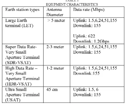
of equipment available are given in Table 1.(EIRP)
+Ls
+La+Gr
+228.6 TABLEIEQIUPMENT CHARACTERISTICS
C/N= (EIRP)+
Ls
+La+Gr /Ts
+228.6-10logTs-10logB
Earth stationtypes Antenna Datarate(Mbps)Diameter
G=-
1
59.59+
20logD
+
20logf
+
20log'q
|LargeEarth
>5meter Uplink: 1.5,6,24,51,155G~~-159.59 ±2OlogD ± 2Ologf ± 20logr~~~ terminal(LET) Downlink: 155
Uplink:622
V.DESIGN ASPECTS SuperData Rate- 2-3 meter Downlink:Uplink: 1.5,6,24,51,1551.2Gbps
SDR-VSAT (Supper high Data Rate-Very Small Aperture ApertureVerySmallTerminal
Downlink:
155 Terminal) and LET (Large Earth Terminal) have a TDMA (SDR-VSAT)(Time Domain Multiple Access) function by receiving reference HighData Rate- 1-2meter Uplink: 1.5,6,24,51,155
burst sent from WINDS (Wideband Internetworking Very Small Downlink:155
Engineering Test and Demonstration Satellite). [8] The Aperture Terminal
proposed ground station will be operated on both modes by UltraSmall 45 cm Uplink: 1.5,6 using electronically steerable beam antaean, +/-7degrees inthe ApertureTerminal Downlink: 155 north-south direction and+/-8 degreesintheeast-westdirection, (USAT)
which has antenna array with amplifiers and phase shifters
including and Asynchronous Transfer Mode (ATM) Switching Large Earth terminal (LET) and Super Data Rate-Very Small Router -a Layer-2 protocol commonly used in broadband Aperture Terminal (SDR-VSAT) can be operated at the data rate given in networks. Featuring advanced QoS control to multi-media Table1 by usingboth ofthe beams: Multi Beam Antenna(MBA)andActive
communication. [8] Phase Array Antenna. MBA and APAAboth can be operated in Onboard
The
analysis
demonstrates thatperformance
parameters
Aperture Terminalswitching and bent-pipe(HDR-VSAT) and Ultra Small Aperture Terminalmodes. Whereas High Data Rate -Very Small including EIRP and G/T of APAA (Active-phasedAntenna) are (USAT) can operate MBA switching mode.less thanATMswitched modeusing FixedBeam MBA
(Multi-beam antenna). Subsequently larger earth stations antenna is VI. LINK ANALYSIS required forAPAA.For ATM base band switching mode, Data
Transmission capacityinthe modedependsontheperformance The link budget provides the designer with values of ofWINDStransponder and the performance of proposed earth transmitter power and antenna gains for the various links in station. 155 Mbps and622Mbps arethe basic transmissionrate the ground station systems is one of the key items in a space in the WINDS network in both bent-pipe and ATM switched systems deign, revealing many characteristics of overall mode. The information for TDMA communication will be systems performance. The following tables show the link modulated by the mean ofbent-pipe mode.[8] performance of the proposed ground station facility to be
located in Malacca, Malaysia for WINDS System. The Design aspects of Malaysian Ground Facility
aim for maximum speed of 155Mbps for downlink (receiving)
[image:2.595.317.537.311.493.2]TABLE 2
LINK DESIGNFOR MBA2 TABLE 6
Parameters Uplink Down link APAA LINKDESIGNFOR 2.5mANTENNASIZE(OPTION-1)
Frequency 28.05 GHz 18.25 GHz Parameters Uplink Downlink
EIRP 72.6dBW 65.2dBW Frequency 28.05 GHz 18.25 GHz
G/T 17.7dB/K 24.5dB/K EIRP 71.2 dBW 54.3 dBW
EIRP 76.OdBW 80.0dBW Power(Tx) 19.4 dBW
Total Losses -215.8dB -210.1dB Antenna Gain 53.9 dBi (2.5m)
-TotalC/No 103.2dB.Hz 103.2dB.Hz Slant Range 40794.7 40794.7
RequiredEb/No 7.3dB BER5X10-4 Total Losses -374.4 dbW -379.5 dBW
RequiredCb/N0 100.2dB.Hz BER5X10-4 G/T 6.7 dB/K 24.5 dB/K
Bit Rate 88.9dB.Hz 782Mbps ReceivedC/No 89.6 dB.Hz 94.9 dB.Hz
RequiredC/No 88.7dB.Hz 93.9dB.Hz
LinkMargin 1.0dB 1.0dB
TABLE 3 Modulation QPSK QPSK
APAALINK DESIGNFOR 10.2 mANTENNASIZEOPTION-4) RequiredEb/NQ 7.3dB(BER:5.OE-4) 7.3dB (BER 5E-4)
Parameters Uplink Downlink
Bit Rate,,
78.7 dB.Hz
(74.0 Mb) 83.1dBHz (204 Mb)
Frequency 28.05 GHz 18.25 GHz
EIRP 81.1dBW 54.3dBW
Power(Tx) 17.0dBW VII. SUMMARY OF LINKANALYSIS
AntennaGain 66.3dBi(10 .2m)
SlantRange 40794.7 40794.7 For
option-I
in Table 6, the antenna size is less than Total Losses -374.4 dbW -379.5 dBW 2.5meter,Transmitting
Power is 87.0 W,EIRP
is71.2
dBW Received C/No 89.7 dB.Hz 101.4dB.Hz and Noise power density is -203.9 dBW/Hz with 1 dB linkRequiredC/No 88.7 dB.Hz 93.9 dB.Hz margin..
LinkMargin 1.0dB 7.5dB
Modulation QPSK QPSK For option-2 in Table 5, the antenna size is less than
Required
Eb/NQ
7.3 dB(BER:5.OE-4) 7.3 dB (BER 5E-4) 3.3meter,
Transmitting Power is 50.0W,
EIRP is 71.2 dBW [image:3.595.64.296.88.360.2] [image:3.595.337.565.89.239.2]Bit Rate,
78.7
dB.Hz (74.0 Mb) 83.dBHz(204 Mb) andNoise
power density is -203.9 dBW/Hz with link margins of 1 dB and 3.5 dB for uplink and downlinkTABLE 4
respectively.
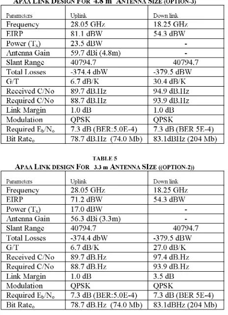
APAALINK DESIGN FOR 4.8m ANTENNA SIZE(OPTION-3)
Parameters Uplink Downlink For
option-3
in Table 4, the antenna size is less than Frequency 28.05 GHz 18.25 GHz 4.8 meter, TransmittingPower is 50.0 W,EIRP is 81.1 dBWEIRP 81.1 dBW 54.3 dBW and Noise power density is --202.4
dBW/Hz
with linkPower(Tx) 23.5 dBW
margins
of I dB and 7.5 dB foruplink
and downlinkAntennaGain 59.7dBi(4.8m) -
rgind
BkoSlant Range 40794.7 40794.7 respectively.
TotalLosses -374.4dbW -379.5dBW
G/T 6.7 dB/K 30.4dB/K For
option-4
inTable3,
theantenna size is lessthanReceivedC/No 89.7 dB.Hz 94.9 dB.Hz 10.2 meter, Transmitting Power is 225.0 W, EIRP is 81.1 RequiredC/No 88.7 dB.Hz 93.9 dB.Hz dBWand Noise power density is --202.4
dBW/Hz
with linkLinkMargin 1.0dB 1.0 dB
LinkuMagion
1.0K dBSK
1.0dmargins
of1 dB for bothuplink
anddownlink.
Modulation QPSK QPSK
RequiredEb/NQ 7.3dB(BER:5.OE-4) 7.3dB(BER 5E-4)
Bit
Rate0
78.7 dB.Hz (74.0 Mb) 83.1dBHz(204Mb)
Alloptions
based onthe ITU-Rantennapattern
29-251og0.All
optionsarebasedonanalysis performed for QPSK TABLE5 modulationScheme.All
analysis was carried out under clearAPAA LINKDESIGNFOR 3.3 mANTENNA SIZE ((OPTION-2))
sky
conditions. The linkmargins
aresubject
theavailability
Parameters Uplink Downlink of thelinks at a certain a certain time and location.
Frequency 28.05 GHz 18.25 GHz
EIRP 71.2dBW 54.3dBW
Power (Tx) 17.0 dBW
~~~VIII.
FREQUENCYCOORDINATIONPower(Tx) 17.0dBW AntennaGain 56.3dBi(3.3m)
SlantRange 40794.7 40794.7 For the proposed earth station and radio equipment, Total Losses -374.4 dbW -379.5dBW the technical regulation and operation methods
specified
in G/T 6.7 dB/K 27.0 dB/K the ITU radio Regulations and other local andinternational
ReceivedC/No 89.7 dB.Hz 97.4dB.Hz laws will be observed.
However,
a radio station license isRequired C/No 88.7 dB.Hz 93.9 dB.Hz req e t
Link Margin 1.0 dB 3.5 dB eurdtco utthexri n.
Modulation QPSK QPSK
RequiredEb/NQ 7.3 dB(BER:5.OE-4) 7.3 dB (BER5E-4) IX. RECOMMENDATIONS
BitRate0 78.7 dB.Hz (74.0 Mb) 83.1dBHz(204 Mb)
[image:3.595.64.296.397.717.2]Based on the analysis given above, werecommend the following for the Earth Station design using WINDS systematKuala Lumpur andMalacca, Malaysia:
The results given in Tables 5 & 6 demonstrate that the best available equipment for the options 1 & 2 is Super
Data Rate-VerySmall Aperture Terminal (SDR-VSAT)for APAA in both on
board switching and bent pipe modes.
The results given in Tables 3 & 4 demonstrate that the best available equipment for the options 3 & 4 is Large
Earth terminal (LET) for APAA in both on boardswitching and bent pipe
modes.
X. CONCLUSION
WINDS experiment to be conducted by JAXA, Japanis a good opportunity for the countries undercoverage to
verify
and validate Ka-band technology by conducting various experiments including but not limited to Tele-education, Tele-medicine, Propagation Modeling, Interference and compatibility analysis at ultraspeed.The proposed Earth Station Design is to conduct above-mentioned experiments at University Technical Malaysia, Malacca (UTeM) for acquiring technical know-howinKa-band communications Technolgy.
XI. REFERENCES
[1] GaryG.Whitworth, "Ground Systems Design andSizing", Space MissionAnalysis and Design,SpaceTechnology Library, MicrocosmPress, ELSegundo, California and Kluwer Academic publisher, London.
[2] Klements,H.D.1987.AirForceSatellite ControlFacility Space/Ground Interface. TOR-0059(6110-01).EL Segundo,CA:The Aerospace Corporation
[3] Martin, DonaldH. 1984.CommunicationsSatellite,1985to 1986.Report No. SD-TR-85-76.EL Segundo,CA:The Aerospace Corporation.
[4] Pratt,Timothy and Charles W.Bostian,1986.Satellite Coomunications.New York:JohnWilley& Sons.
[5] Roger L. Freeman,TelecommunicationsTransmission,4thed, A
willey-Interscience publication,NewYork. [6] Roger L. Freeman,Radio SystemDesign for
Telecommunications,2nded, WileyNewYork,1997. [7]"VSATSystems and EarthStations," Handbook of Satellite
Communications,3rded ITU-Radio Communication Bureau, Geneva,2002.
[8] WINDS'sDocumentsprovided by JAXA,JAPAN-2006.