AN INVESTIGATION OF MOTORCYCLE DISC BRAKE ROTOR USING FINITE ELEMENT METHOD
KAMAL RUZUAN B MAT HUSSIN
“I hereby verify that I have read this report and I find it sufficient in term of quality and scope to be awarded with the Bachelor Degree in Mechanical Engineering “
Signature : ………
Supervisor Name : ………
AN INVESTIGATION OF MOTORCYCLE DISC BRAKE ROTOR USING FINITE ELEMENT METHOD
KAMAL RUZUAN B MAT HUSSIN
This thesis report submitted to Faculty of Mechanical Engineering in partial fulfill Of the requirement of the award of Bachelor’s Degree of Mechanical Engineering
(Automotive)
Faculty of Mechanical Engineering
UNIVERSITI TEKNIKAL MALAYSIA MELAKA
“I hereby to declare that the work is my own except for summaries and quotations which have been duly acknowledge”
Signature : ……….
iii
DEDICATION
To him who is our source of grace, our source of commitment, and our source of knowledge,
And,
ACKNOWLEDGMENT
First of all I thank god for the blessing upon me to finish up this report. I would like to express my gratitude and appreciation to my supervisor, Mr. Ridzuan b. Mansor for his valuable suggestion and advice throughout this project.
v
ABSTRACT
ABSTRAK
vii
TABLE OF CONTENTS
CONTENTS PAGE
DECLARATION ii
DEDICATION iii
ACKNOWLEDGEMENT iv
ABSTRACT v
ABSTRAK vi
TABLE OF CONTENTS vii
LIST OF TABLES xi
LIST OF FIGURES xii
LIST OF SYMBOLS xv
LIST OF APPENDIX xii
CHAPTER 1 INTRODUCTION
1.1 Introduction 1
1.2 Overview of Disc Brake System 2
1.3 History of Disc Brake Rotor 4
1.4 Rotor 5
1.5 Brake Caliper 7
1.6 Brake pad 11
1.7 Objective 16
1.8 Research scope 16
1.9 Problem Statement 16
CHAPTER 2 LITERATURE REVIEW
2.1 Previous Research on Disc Brake
Thermal Analysis 18
2.2 Heat Transfer 21
2.5.1 Conduction Heat Transfer 22 2.5.2 Convection Heat Transfer 23 2.5.3 Radiation Heat Transfer 24
2.3 Finite Element Method (FEM) 26
2.3.1 Brief History 27
2.3.2 Type of Problem in Finite Element
Method 28
2.3.3 The Working Principle of Finite
Element Method 29
2.4 Theory of Failures 31
2.4.1 Fatigue Failures 31
2.4.2 Crack Initiation 32
2.4.3 Crack Nucleation 33
2.4.4 Crack Propagation 34
2.4.5 Thermal Fatigue 35
CHAPTER 3 METHODOLOGY
3.1 Introduction 37
3.2 Material Properties 37
3.2.1 Gray Cast Iron 38
3.3 Design the Rotor 40
3.4 Analysis 42
3.4.1 Pre-processing 43
ix
3.5 Finite Element Modeling 45
3.6 Safety Factor 47
3.7 Periodic Braking Operation 48
3.7.1 Braking Pattern 49
3.7.2 Heat Flux and Initial Temperature 50
3.8 Assumption of Simulation 53
3.9 Centre of Gravity 54
3.10 Height of Centre of Gravity 55
CHAPTER 4 RESULT AND DISCUSSION
4.1 Calculation 60
4.1.1 Calculation for determining Weight transfer 60 4.1.2 Calculation for determining Braking
Power and Generated Heat Flux 61 4.1.3 Calculation for determining Thermal
Boundary Condition (Convective Heat
Transfer Coefficient, h) 62
4.1.3.1 Braking Surface 62
4.1.3.2 Outer Ring Surface 63 4.1.3.3 Cross-drilled Holes 64
4.2 Result 66
4.2.1 Temperature Distribution on Rotor
Surface 66
4.2.1.1 Initial Temperature 66 4.2.1.2 First Cycle of Brake Fade Test
(Cooling Process) 67
4.2.1.3 First Cycle of Brake Fade Test
(Heating Process) 71
4.2.1.4 Maximum Temperature Distribution 73
4.2.2 Nodal Temperature 75
4.2.3 Maximum Stress Distribution and Maximum
4.3 Discussion 86
CHAPTER 5 CONCLUSION AND RECOMMENDATION
5.1 Conclusion 87
5.2 Recommendation 88
REFERENCES 90
BIBLIOGRAPHY 91
xi
LIST OF TABLES
TABLE TITLE PAGES
Table 3.1 The material distribution of Gray Cast Iron
composition in percentage 39
Table 3.2 The mechanical properties of Gray Cast Iron 39 Table 3.3 The thermal properties of Gray Cast Iron 40 Table 3.4 Geometric dimensions and material properties
of disc brake rotor 41
Table 3.5 Overall dimensions of Yamaha Lagenda 110Z
Motorcycle 41
Table 3.6 The elements properties for disc brake rotor
thermal analysis 45
LIST OF FIGURES
FIGURE TITLE PAGES
Figure 1.1 Simple diagram of braking system 3
Figure 1.2 Solid rotor 5
Figure 1.3 Ventilated rotor 5
Figure 1.4 Fixed Caliper 8
Figure 1.5 Floating Caliper 10
Figure 1.6 Riveted lining 12
Figure 1.7 Bonded lining 13
Figure 1.8 Aramid fibre 15
Figure 2.1 Finite element mesh 26
Figure 3.1 Current model of motorcycle disc brake rotors 40
Figure 3.2 Process Flow of ABAQUS 42
Figure 3.3 Work flow of thermal stress analysis 44 Figure 3.4 The location on the rotor that is constrained (in red colour) 46 Figure 3.5 The graph of motorcycle’s speed against time for single
cycle of brake fade test 49
Figure 3.6 The graph of motorcycle’s speed against time for overall
brake fade test 50
Figure 3.7 The graph of heat flux amplitude against time 51 Figure 3.8 Heat flux is applied to braking surface (indicated by red
colour surfaces) of rotor on both inboard and outboard
xiii
Figure 3.9 At the end of first cycle braking operation, the temperature of rotor is assumed to be at 50˚C. This is done by defining the whole rotor (red colour) experience
such condition 52
Figure 3.10 Static Load of Motorcycle on Level Position 54 Figure 3.11 Change of distance between centre of gravity to front axle
and rear axle when inclining 56
Figure 3.12 Static load on motorcycle on inclined position (rear axle is
elevated higher than front axle) 56
Figure 3.13 Static load on motorcycle on inclined position (front axle is
elevated higher than rear axle) 57
Figure 4.1 Corresponding Braking Surface 62
Figure 4.2 Corresponding Outer Ring Surface 63
Figure 4.3 Corresponding cross-drilled holes 64
Figure 4.4 The initial temperature of disc brake rotor 66 Figure 4.5 The flow of diagrams for first cooling cycle of disc brake
rotor at certain period of time 67
Figure 4.6 The temperature distribution on rotor interface for first
one second of cooling 67
Figure 4.7 The temperature distribution on rotor interface when
cooling speed is achieved 69
Figure 4.8 The temperature distribution on rotor interface at the end
of first cycle of cooling process 70
Figure 4.9 The flow of diagrams for first heating cycle of disc brake rotor taken at every second of five seconds heating period 71 Figure 4.10 The temperature distribution on rotor interface for first one
second of first cycle heating process 72 Figure 4.11 The temperature distribution on rotor interface at the end of
first cycle heating process 73
Figure 4.12 The maximum temperature distribution for ten cycle’s
periodic brake fade test 74
Figure 4.13 Graph temperature versus time at node number 349 75 Figure 4.14(a) Contour represents stress distribution
Figure 4.14(b) Contour represents stress distribution
on rotor model (front view) 82
Figure 4.14(c) Contour represents stress distribution
on rotor model (upper view) 82
Figures 4.14(d) Contour represents stress distribution
on rotor model at specific location 83 Figures 4.15(a) Contour represents displacement distribution
on rotor model (3 Dimensional View) 84
Figures 4.15(b) Contour represents displacement distribution
on rotor model (front view) 84
Figures 4.15(c) Contour represents displacement distribution
on rotor model (upper view) 85
Figures 4.15(d) Contour represents displacement distribution
xv
LIST OF SYMBOLS
WT
m total
a
CGH
WB
m moto
W moto
W total
% WT
KE
u
t brake
Pbrake
Pbrakefront
Abrake
Re
ω rotor
r outer ν air
Nu
h
k air
D outer
Pr ρ air = = = = = = = = = = = = = = = = = = = = = = = = =
Weight transfer to front axle (N) Total mass of motorcycle (kg) Deceleration of motorcycle (ms -2)
Center of gravity’s height of motorcycle (m) Wheelbase of motorcycle (m)
Mass of motorcycle (kg) Weight of motorcycle (N) Total weight of motorcycle (N)
The percentage of weight transfer to front axle Kinetics energy of motorcycle (J)
Speed of motorcycle (ms-1)
Time taken for braking process (s) Total braking power for motorcycle (W) Braking power at front axle (W)
Total brake surface area on rotor (m2) Reynold’s number
Rotational speed of rotor (rad s-1) Outer radius of brake rotor (m) Kinematics viscosity of air (m2 s-1) Nusselt’s number
Convective heat transfer coefficient (Wm-1˚C1) Thermal conductivity of air (Wm-1˚C-1)
Outer diameter of brake rotor (m) Prandtl’s number
u avg
µ air
dh
l
= = =
=
Average speed of motorcycle (ms -1) Dynamics viscosity of air (kgm-1 s-1)
Diameter of cross-drilled holes on rotor braking surface (m)
xii
LIST OF APPENDIX
FIGURE TITLE PAGES
CHAPTER 1
INTRODUCTION
1.1 Introduction
2 system along is incomplete without handling instrument such as steering system and braking system. Because the travel courses are not always straight and vehicle need to be maneuvered properly to prevent from going off the track. Braking system is not only provides the means to slowing down and stop a vehicle. It also ensures stationary position of vehicle can be maintained especially when standing on steep road. In spite of brake system is as crucial as it concerns to safety of passengers onboard, malfunction of even one component should be avoided as it tends to defect overall braking operation. Catastrophic disaster can be prevented from happening if precautions are taken. The counter measures like servicing critical components regularly and make sure that those components used are genuine part whose approved its quality thus reduce chance of brake fail.
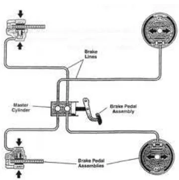
1.2 Overview of Disc Brake System
The purpose of braking system can be simplified into three objectives. First, to make the vehicle stop at certain instance when desired or to avoid collision. Second, to keep the vehicle sped at controllable velocity especially when downhill. And last one is to keep the stationary vehicle stand still under acceptable condition such as on low grade. Brake system operates by actuating the force from muscle through mechanical, electrical, hydraulic or combination of two or more media transmit the power to end components. Friction brakes do the job by converting kinetic energy of moving vehicle into frictional heat energy due to forced contact between rotating drum or brake disc with fixed pads or brake shoes. Substantial portion of heat generated during braking will be absorbed by rotating part (brake drum or rotor), and the remaining will be dissipated to ambient.
vehicle. The third one is hydraulic system; the system supplies braking force alternatively connects a system to other. Function of this system is to direct the braking force induced by the pressure of confined fluid through tubes and hoses to wheel brakes. The last system in braking structure which links by brake fluid is wheel brake cylinder or brake calliper. This component actuate as the braking force applied to pedal thus manipulate frictional part (brake pad or brake shoe) to press against rotating drum or rotor.
Generally the foundation of brake system can be short listed to several components. The combination of two or more components forms small subsystems which integrate together working as overall brake system. Brake system is distinguished by the two common things; disc brake and drum brake. Disc brake simply consists of disc brake rotor, brake pad and brake calliper. While drum brake contains pan-like drum, brake shoe and brake wheel cylinder.
Figure 1.1: Simple diagram of braking system (source: courses.gmtraining.com)
4 thus transmit braking force through fluid medium. Finally, fluid pressure will reach the brake caliper and actuate caliper piston inside. By attaching brake pad to the caliper piston, pressure will act the brake pad against rotating disc brake rotor and clamping both sides of disc brake rotor’s swept areas. As the pad linings touch rotor surface, frictional drag gradually increase to slow down the rotational speed of rotor thus decrease vehicle’s speed. In the end of braking operation driver will release brake pedal, hence the pressure inside brake hydraulic lines will relax. Here the self-adjustment regulates the position of brake pad back into release state by compensating slight wear of pad lining and the retraction of piston seal holding down caliper’s piston.
1.3 History of Disc Brake Rotor
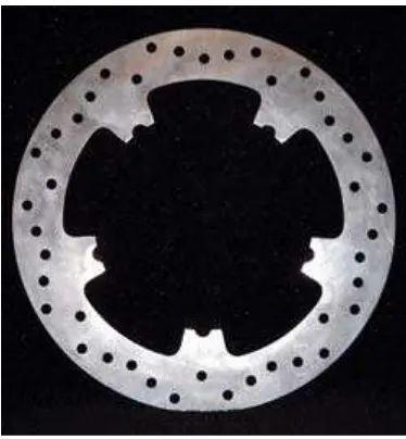
1.4 Rotor
In friction brake, the rotor serves by implementing braking mechanism of contact friction between two surfaces. So, the requirement of platform for contact interaction idealizes a structure called disc brake rotor. A simple construction of rotor has frictional surfaces and centre section. Solid rotor can be identified by the solid plane of frictional surface, sometimes with cross-drilled holes on it.
Figure 1.2: Solid rotor (Source: www.ebcbrakes.com)
Another design called ventilated rotor differs by additional ventilation vanes located at centre between inboard and outboard sides of rotor.