RECONFIGURABLE DUAL POLARIZATION ANTENNA
CHUA PEI YONG
This Report is Submitted in Partial Fulfillment of Requirements for the Bachelor Degree of Electronic Engineering
Faculty of Electronic and Computer Engineering Universiti Teknikal Malaysia Melaka
UNIVERSTI TEKNIKAL MALAYS IA MELAKA FAKULTI KEJURUTERAAN ELEKTRONIK DAN KEJURUTERAAN
KOM PUTER
BO RANG PENGESAHAN STATUS LAPORAN
PROJEK SARJANA MUDA II
Tajuk Projek : RECONFIGURAB LE DUAL POLARIZATION ANTENNA
Sesi Pengajian : 1 2 / 1 3
Saya CHUA PEI YONG
Mengaku membenarkan Laporan Projek Sarjana Muda ini disimpan di Perpustakaan dengan syarat-syara tkegunaan seperti berikut:
1. Laporan adalah hakmilik Universiti Teknikal Malaysia Melaka.
2. Perpustakaan dibenarkan membuat salinan untuk tujuan pengajian sahaja.
3. Perpustakaan dibenarkan membuat salinan laporan ini sebagai bahan pertukaran antara institusi pengajian tinggi.
4. Sila tandakan ( √ ) :
SULIT*
*(M engandungi maklumat yang berdarjah keselamatan atau kepentingan M alaysia seperti yang termaktub di dalam AKTA RAHSIA RASM I 1972)
TERHAD** **(M engandungi maklumat terhad yang telah ditentukan oleh organisasi/badan di mana penyelidikan dijalankan)
TIDAK TERHAD
Disahkan oleh:
__________________________ ___________________________________
iii
“I hereby declare that this thesis is the result of my own work except for quotes as
cited in the references.”
Signature : ……….
Author : CHUA PEI YONG
iv
“I hereby declare that I have read this thesis and in my opinion this thesis is sufficient in terms of the scope and quality for the award of Bachelor of Electronic Engineering
(Wireless Communication) With Honours.”
Signature : ……….
Supervisor’s Name : MR. ABD SHUKUR BIN ABD JAAFAR
v
vi
ACKNOWLEDGEMENT
First of all, I’ll like to express my sincere gratitude to my supervisor, Mr. Abd. Shukur bin Jaafar and my co-supervisor Mr. Mohamad Zoinol Abidin bin Abd. Aziz for giving me encouragement, guidance, critics, advice, information and motivation throughout this project.
Besides, I would also like to extend my appreciation to all my friends who provided assistance at various occasions and giving me some useful view and tips.
vii
ABSTRACT
viii
ABSTRAK
Oleh kerana isyarat tidak bergerak hanya atas garisan penglihatan, ia sampai ke destinasi melalui pelbagai laluan dan menyebabkan kesan berbilang laluan yang mungkin melemahkan penerimaan isyarat. Dwi polarisasi antena dapat mengatasi masalah ini di mana ia boleh menangani kesan berbilang laluan, meningkatkan prestasi sistem, mengurangkan gangguan, dan meningkatkan keupayaan saluran. Selain itu, ciri konfigurasi membolehkan jenis polarisasi antena boleh dipilih. Objektif utama projek ini adalah untuk mereka bentuk, simulasi dan fabrikasi dwi polarisasi antena yang boleh konfigur. Antena ini boleh beroperasi pada frekuensi salunan 2.4GHz dengan kehilangan pulangan -10dB dan jenis polarisasi boleh tukar dengan menggunakan diod PIN. Proses reka bentuk antena bermula dari antena tunggal linear polarisasi dan antena tunggal polarisasi bulat, antena dwi polarisasi dan akhir sekali dwi polarisasi antena yang boleh konfigur. Kemudian, antena akan disimulasikan dengan menggunakan perisian CST, fabrikasi dan pengukuran. Keputusan untuk simulasi dan pengukuran menunjukkan bahawa antena direka bentuk mempunyai frekuensi salunan 2.4GHz dan mampu menghasilkan dwi polarisasi iaitu polarisasi membulat tangan kiri dan polarisasi membulat tangan kanan. Tambahan pula, jenis polarisasi dapat bertukar dengan adanya kuasa luar yang
dibekalkan kepada diod PIN untuk mencetuskan keadaan ‘buka’ dan ‘tutup’. Antena
ix
TABLE OF CONTENT
CHAPTER TITLE PAGE
PROJECT TITLE i
THESIS VERIFICATION STATUS ii
DECLARATION iii
SUPERVISOR’S APPROVAL iv
DEDICATION v
ACKNOWLEDGEMENT vi
ABSTRACT vii
ABSTRAK viii
TABLE OF CONTENTS ix
LIST OF TABLES xiii
LIST OF FIGURES xiv
LIST OF ABBREVATION xvii
LIST OF SYMBOLS xviii
LIST OF APPENDICES xx
I INTRODUCTION
1.1 INTRODUCTION 1
1.2 PROBLEM STATEMENT 2
1.3 OBJECTIVE 3
1.4 SCOPE OF WORK 3
1.5 METHODOLOGY 4
x
II LITERATURE REVIEW
2.1 MICROSTRIP PATCH ANTENNA 6
2.2 RECONFIGURABLE ANTENNA 7
2.3 RECONFIGURABLE TECHNIQUES 7
2.4 LINEAR POLARIZATION ANTENNA 9
2.5 CIRCULAR POLARIZATION ANTENNA 10
2.6 DUAL POLARIZATION ANTENNA 11
III DESIGN OF RECONFIGURABLE DUAL
POLARIZATION ANTENNA
3.1 DESIGN SPECIFICATION 13
3.2 LINEAR POLARIZATION ANTENNA 15
(DESIGN A)
3.2.1 Rectangular Patch Antenna with Inset Feed 15 Line (Design A1)
3.2.2 Circular Patch Antenna with Coaxial 17 Probe (Design A2)
3.2.3 Circular Patch Antenna with Feed Line 18 (Design A3)
3.3 CIRCULAR POLARIZATION ANTENNA 19
(DESIGN B)
3.3.1 Truncated Corner Rectangular Patch 20 Antenna (Design B1 and Design B2)
3.3.2 Dual Slot Circular Patch Antenna with 21 Coaxial Probe (Design B3 and Design B4)
xi
3.4 DUAL POLARIZATION ANTENNA (DESIGN C) 23 3.4.1 Dual Slot Circular Patch Antenna with 23
Dual Feed Line (Design C1)
3.4.2 Improved Dual Slot Circular Patch 25 Antenna with Dual Feed Line by Adding
Stubs, Slits and Stacked Patch (Design C2)
3.5 RECONFIGURABLE DUAL POLARIZATION 28
ANTENNA (DESIGN D)
3.6 SIMULATION PROCESS 29
3.7 FABRICATION PROCESS 30
3.8 MEASUREMENT PROCESS 31
IV RESULTS AND DISCUSSION
4.1 LINEAR POLARIZATION ANTENNA 32
(DESIGN A)
4.2 CIRCULAR POLARIZATION ANTENNA 35
(DESIGN B)
4.3 DUAL POLARIZATION ANTENNA (DESIGN C) 43
4.4 RECONFIGURABLE DUAL POLARIZATION 46
ANTENNA (DESIGN D)
4.4.1 Comparison between Design C2 and 54 Design D
4.5 OVERALL COMPARISON FOR ALL ANTENNA 55 DESIGN
V CONCLUSION AND SUGGESTION
5.1 CONCLUSION 57
xii
REFERENCES 59
APPENDIX A 63
APPENDIX B 64
APPENDIX C 66
xiii
LIST OF TABLES
NO TITLE PAGE
2.1 Comparison between Reconfiguration Techniques 8
3.1 Design Specification 14
4.1 Comparison on Antenna Parameter of Linear Polarization 35 Antenna (Design A)
4.2 Comparison on Antenna Parameter for Circular Polarization 37 Antenna (Design B)
4.3 Surface Current for Design B1 and B2 38
4.4 Surface Current for Design B3 and B4 39
4.5 Surface Current for Design B5 and B6 41
4.6 Comparison on Antenna Parameter for Dual Polarization 44 Antenna (Design C)
4.7 Surface Current for Design C 45
4.8 Simulation Result on Antenna Parameter for Reconfigurable 50 Dual Polarization Antenna (Design D)
4.9 Surface Current for Design D when Diode A is ‘ON’ 51 4.10 Surface Current for Design D when Diode B is ‘ON’ 52 4.11 Comparison on Antenna Parameter for Design C2 and 55
Design D
xiv
LIST OF FIGURES
NO TITLE PAGE
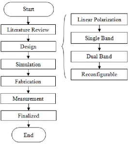
1.1 Project Flowchart 4
2.1 Basic Microstrip Patch Antenna 6
2.2 Reconfigurable Techniques (a) PIN diode (b) FET 8 (c) RF MEMs Switch
2.3 Linear Polarization (a) Vertical (b) Horizontal 9 2.4 Type of Linear Polarization Antenna (a) Inset Feed 9
Rectangular Patch (b) Four Element Electromagnetically Coupled Patch
2.5 Circular Polarization (a) Right-handed (b) Left-handed 11 2.6 Type of Circular Polarization Antenna (a) Circular Slot 11
Antenna (b) Square Slot Antenna
2.7 Type of Dual Polarization Antenna (a) Square Patch 12 Antenna with Dual Feed (b) Slot Ring Antenna with
CPW Feed (c) Single Layered Antenna
3.1 Rectangular Patch Antenna (Design A1) 15
3.2 Parametric Study of g on S-Parameter for Design A1 17 3.3 Circular Patch Antenna with Coaxial Probe (Design A2) 17 3.4 Parametric Study of Pc on S-Parameter for Design A2 18 3.5 Circular Patch Antenna with Feed Line (Design A3) 19 3.6 Parametric Study of Wf on S-Parameter for Design A3 19 3.7 Truncated Corner Rectangular Patch Antenna for 20
xv
3.8 Parametric Study of Ltc on (a) S-Parameter and 21 (b) AR for Design B1
3.9 Dual Slot Circular Patch Antenna with Coaxial Probe for 22 (a) Right-handed Circular Polarization (Design B3)
(b) Left-handed Circular Polarization (Design B4)
3.10 Dual Slot Circular Patch Antenna with Feed Line for 23 (a) Right-handed Circular Polarization (Design B5)
(b) Left-handed Circular Polarization (Design B6)
3.11 Dual Polarization Antenna (Design C) 24
3.12 Improved Dual Polarization Antenna (Design C2) 25 (a) Front View without Stacked Patch (b) Stacked Patch
(c) Side View
3.13 Parametric Study of stub on Gain for Design C2 (Port 1) 26 3.14 Parametric Study of slit on S-parameter for Design C2 27
(Port 1)
3.15 Parametric Study of gstack on Gain for Design C2 (Port 1) 27 3.16 Parametric Study of Sstack on Gain for Design C2 (Port 1) 27 3.17 Reconfigurable Dual Polarization Antenna (a) Position of 28
Gap (b) Position of Diodes and Jumper (c) Side View
3.18 Waveguide Port for (a) Feed Line and (b) Coaxial Probe 29
3.19 Flowchart of Fabrication Process 30
3.20 Measurement Setup for (a) S-parameter 31
(b) Radiation Pattern
4.1 Linear Polarization Antenna (a) Design A1 (b) Design A2 33 (c) Design A3
4.2 Simulation Result on S-Parameter for Design A 34 4.3 Circular Polarization Antenna (a) Design B1 (b) Design B2 35
(c) Design B3 (d) Design B4 (e) Design B5 (f) Design B6
4.4 Simulation Result on S-parameter for Design B 37 4.5 Dual Polarization Antenna (a) Design C1 (b) Stacked Patch 42
of Design C2 (c) Design C2
xvi
4.8 Simulated Result on S-parameter for Design D 47 4.9 Measured Result on S-parameter for Design D (a) Port 1 48
(b) Port 2
4.10 Comparison between Simulated and Measured Result on 49 S-parameter when All Diode is (a) ‘ON’ and (b) ‘OFF’
xvii
LIST OF ABBREVATIONS
AUT - Antenna Under Test
CPW - Coplanar Waveguide
CST - Computer Simulation Technology
dB - decibel
FET - Field-effect Transistor
GHz - Gigahertz
IEEE - Institute of Electrical and Electronics Engineers LAN - Local Area Network
LTE - Long Term Evolution
MEMs - Microelectromechanical system
MHz - Megahertz
RF - Radio Frequency
xviii
LIST OF SYMBOLS
AR - Axial Ratio
BW - Bandwidth
c - Speed of light
D - Directivity
Ɛr - Dielectric Constant
- Effective Dielectric Constant
E - Efficiency
- Resonant Frequency
g - Gap
gstack - Gap between Stacked Patch and Circular Patch
G - Gain
h - Height of Copper
hs - Height of Substrate
hstack - Height of Stacked Patch
- Effective Length Lf - Length of Feed Line
Lp - Length of Patch
Ls - Length of Substrate
Ltc - Length of Truncated Corner
Pc - Coordinate of Coaxial Probe
Pif - Position of Inset Feed Line
Rbs - Radius of Big Circular Slot
RL - Return Loss
Rp - Radius of Patch
xix
slit - Size of Square Slit
Sstack - Size of Stacked Patch
stub - Size of Square Stub
- Tangential loss
Wf - Width of Feed Line
Wp - Width of Patch
Ws - Width of Substrate
xx
LIST OF APPENDICES
NO TITLE PAGE
A Circular Patch Antenna with Feed Line (Design A3) 63 B Dual Slot Circular Patch Antenna with Coaxial Probe 64
(Design B3 and Design B4)
C Dual Slot Circular Patch Antenna with Feed Line 66 (Design B5 and Design B6)
1
CHAPTER I
INTRODUCTION
This chapter is discussed about the introduction of the antenna design of reconfigurable dual polarization antenna. Moreover, this chapter also explains on the problem statement, objective, scope of work and methodology.
1.1 Introduction
Antenna is any conductor that can radiate signal. It is needed for systems and devices to transmit and receive signal. Hence, systems and devices can communicate with each other through the aid of antenna. There are a few types of antenna that will be often seen and used in daily life. They are the antenna built in
the phone, router’s antenna, antenna on the radio base station, yagi-uda antenna and Astro antenna used on television. Mobile phone communicate with Wi-Fi router to get the Wi-Fi service while communicate with radio base station to make or receive a phone call. All this can only be done through antenna.
2
There are several antenna parameters that are used to measure antenna performances such as radiation pattern, directivity, gain, resonant frequency, return loss, type of polarization and more. This project will be study on polarization of antenna. Polarization is divided into three main types. They are linear polarization, circular polarization and elliptical polarization. In linear type polarization it is further divided into vertical and horizontal polarization. Meanwhile circular polarization is further divided into right-handed and left-handed polarization. Type of polarization can be observed at the end of the antenna.
Antenna can only communicate with each other if they are in the same polarization which means a vertical linear antenna can only communicate with vertical linear antenna. So a single system with a dual polarization antenna will be able to communicate with more than one other system.
1.2 Problem Statement
Signals are not travelling in line of sight only. They might undergo reflection, diffusion and scattering. Hence, signals usually reach the destination in many ways and this phenomenon known as multipath effects. If the signal travelled from different path and reach the destination 90 degrees out of phase, the signal tends to cancel out each other. Thus, reduce the performance of the antenna. Thus, dual polarization antenna is used to combat the multipath effect [1-5]. If a dual polarization antenna is being used, there were two type of polarization signal travel from the same antenna. Then, these signals reach the same destination as two individual signals. So, they will not recognize each other and the cancellation of signal will not happen. At the same time, it is important in polarization diversity for enhances system performance; reduce the multipath effect and the interference [1-6]. Furthermore, dual polarization antenna can increase the effective channel capacity [6]. This is due to dual polarization antenna can used to communicate with more than one system without extra use of bandwidth or transmit power.
3
external control [7-12]. The properties of the antenna that can be change are polarization, feed, resonant frequency and other. In this project, the polarization of the antenna will be changed. For example the polarization can be change from right-handed polarization to left-right-handed polarization.
1.3 Objective
The main objective of this project is to design, simulate and fabricate the reconfigurable dual polarization antenna. The design antenna will be able to reconfigure the dual polarization which is consisting of linear polarization, right-handed polarization and left-right-handed polarization. Besides, the antenna will be operating at the resonant frequency of 2.4GHz. Furthermore, the designed antenna should meet the minimum requirement where the return loss of the antenna must be less than -10dB and the axial ratio of the linear polarization must be more than 3dB while less than 3dB for circular polarization.
1.4 Scope of Work
The scope of work for this project is divided into four parts which are design, simulation, fabrication and measurement. First is to design reconfigurable dual polarization antenna that can be operate at 2.4GHz where the return loss should be less than -10dB. The dual polarization can be the linear polarization and the circular polarization. The antenna designation will be simulated by using Computer Simulation Technology (CST) software on the parameters such as resonant frequency, polarization, return loss, gain directivity and efficiency. The material that used for fabrication is FR4 board by using the techniques of chemical etching
4
1.5 Methodology
Figure 1.1 explains the methodology used to complete this project. The project started with doing the literature review by study on journals and books regarding the topics of reconfiguration, linear polarization, circular polarization and dual polarization. Then, start to design the antenna of single linear polarization, single right-handed polarization, single left-handed polarization, dual polarization and reconfigurable dual polarization. The dual polarization antenna could be design form combining two single polarization antennas. Then, simulate the entire designed antenna by using CST software. If the result is not desirable, optimization step will be needed; otherwise, move on the fabrication stage. After that, measurement will be made on the antenna prototype.
[image:24.596.188.454.339.644.2]