UNIVERSITI TEKNIKAL MALAYSIA MELAKA
QUALITY INVESTIGATION OF LASER WOOD MACHINING
This report submitted in accordance with requirement of the Universiti Teknikal Malaysia Melaka (UTeM) for the Bachelor Degree of Manufacturing Engineering
(Process) (Hons.)
by
FONG YAN LI B050910014 891227-08-5494
UNIVERSITI TEKNIKAL MALAYSIA MELAKA
BORANG PENGESAHAN STATUS LAPORAN PROJEK SARJANA MUDA
TAJUK: QUALITY INVESTIGATION OF LASER WOOD MACHINING.
SESI PENGAJIAN: 2012 / 2013 - SEMESTER 2
Saya FONG YAN LI
mengaku membenarkan Laporan PSM ini disimpan di Perpustakaan Universiti Teknikal Malaysia Melaka (UTeM) dengan syarat-syarat kegunaan seperti berikut:
1. Laporan PSM adalah hak milik Universiti Teknikal Malaysia Melaka dan penulis. 2. Perpustakaan Universiti Teknikal Malaysia Melaka dibenarkan membuat salinan
untuk tujuan pengajian sahaja dengan izin penulis.
3. Perpustakaan dibenarkan membuat salinan laporan PSM ini sebagai bahan pertukaran antara institusi pengajian tinggi.
(Mengandungi maklumat TERHAD yang telah ditentukan oleh organisasi/badan di mana penyelidikan dijalankan)
Alamat Tetap:
12, Hala Pengkalan Indah 5,
Bandar Pengkalan Indah,
APPROVAL
This report is submitted to the Faculty of Manufacturing Engineering of UTeM as a partial fulfillment of the requirements for the degree of Bachelor of Manufacturing Engineering (Process) (Hons.). The member of the supervisory is as follow:
DECLARATION
I hereby, declared this report entitled “Quality Investigation of Laser Wood Machining” is the results of my own research except as cited in references.
Signature : ……….
Author‟s Name : FONG YAN LI
i
ABSTRAK
ii
ABSTRACT
iii
DEDICATION
iv
ACKNOWLEDGEMENT
I would like to thank to my project supervisor Prof. Madya Ir. Dr. Sivarao who assisted and guided me in order to accomplish this project. The title of the project was “Laser Cutting of Wood” which is a combination of research and experimental based research. This investigation is proposed to wood carving industry in order to solve the problem meet by the industry which using conventional method, jigsaw as the cutting tool for the production. In conjunction to this, I would like to offer my deepest gratitude to Mr. Sivarao from the bottom of my heart for all the support, encouragement, and inspirations manage to obtain all the way through of this project. The excellent working relationship between my supervisor and me has provided me with bountiful knowledge and experience for the future. The help rendered to me is priceless, be in from the smallest of its kind to the largest.
v
TABLE OF CONTENT
Abstrak i
Abstract ii
Dedication iii
Acknowledgement iv
Table of Content v
List of Tables viii
List of Figures x
List of Abbreviations, Symbols, and Specialized Nomenclatures xiii
CHAPTER 1: INTRODUCTION 1
1.1 Background 2
1.2 Problem Statement 7
1.3 Objective 8
1.4 Scope 8
1.5 Proposed method: Laser Cutting 9
1.5.1 Types of Laser 13
1.5.2 Advantages and Limitations of Laser Cutting 16
vi
CHAPTER 2: LITERATURE REVIEW 25
2.1 Laser Cutting 26
2.2 Laser Cutting on Metallic Materials 27
2.3 Laser Cutting on Non-metallic Materials 29
CHAPTER 3: METHODOLOGY 40
3.1 Primary Investigation 41
3.2 Material Selection 41
3.3 Process Parameters: Screening 42
3.4 Selection on Parameters 43
3.5 Experimental Matrix and Design of Experiment (DoE) 45
3.5.1 Factorial Design 47
3.5.2 Level 48
3.5.3 Variable 48
3.6 Experimental Setup 51
3.7 Output Analysis 52
CHAPTER 4: RESULTS AND DISCSSION 54
4.1 Surface Roughness 54
4.1.1 Parallel to Wood Trachieds 55
4.1.2 Perpendicular to Wood Trachieds 60
vii
4.2.1 Top and Bottom Kerf Width 64
4.2.2 Variance of Kerf Width 70
4.3 Discussions 77
CHAPTER 5: CONCLUSION & RECOMMNDATION 82
5.1 Recommendation (Future Work) 83
REFERENCES 85
APPENDIX
A – Example Graphs on Roughness Results B – Data Collections
viii
LIST OF TABLES
1.1 Steps for manually or conventional wood carving process 4
3.1 Inputs and response used in laser cut of wood materials 42 3.2 Frequency for input parameters and responses 43 3.3 The parameters and responses which had arranged
according to descending order 44
3.4 Summary of input and output parameters for laser wood
carving 45
3.5 Basic Specification of Laser Machine Helius – 2531 46 3.6 General cutting parameters for wooden material in previous record 46
3.7 Parameter used for experiment 48
3.8 Number of experiment and parameters used (full
factorial) 50
4.1 Average Ra value measured parallel to wood trachieds 58 4.2 Average Ra value measured perpendicular to wood trachieds 61 4.3 Average kerf width for top and bottom surface 66 4.4 Example measured value for top and bottom kerf width 72
ix
4.6 Comparison of Ra between two cut surfaces 78
x
LIST OF FIGURES
1.1 Wood carving product which used to decorate fence or
staircase 3
1.2 Example of wood carved pattern 9
1.3 Laser cutting descriptions 11
1.4 Examples of three different focal points 13
1.5 Poor cut quality due to high cutting speeds, the sample
thickness 6mm construction steel 19
1.6 A comparison of (a) CW laser cutting and (b) pulsed laser
cutting 20
1.7 Effect of CW and pulsed laser cutting at sharp corner 21 1.8 An illustration of the effect of focal position on cutting
performance (a) Focal distance too high, 3mm (b) Focal distance too low, -2.5mm, (c) Focal distance correct,
0.0mm 23
1.9 Nozzle geometry definitions and nozzle standoff distance 24
3.1 Flow chart for approach the study 40
3.2 Flow of experimental method 51
3.3 Pre-machining design for sample 52
3.4 Measurement of kerf width 53
xi
3.6 Surface roughness measurement across the striation 54
3.7 Surface roughness measurement 54
4.1 Microscopy image of striation (white arrowed) 56 4.2 Laser cut perpendicular (a) and parallel (b) to the wood
trachieds (fibres) 57
4.3 Relationship between Ra value and cutting speed for various gas
pressure at laser power (a) 2.8kW and (b) 2.2kW 59 4.4 Relationship between Ra value and gas pressure for various
laser power at cutting speed (a) 1500mm/min and (b) 1700mm/min 60 4.5 Relationship between Ra value and gas pressure for various
cutting speed at laser power (a) 2.5kW and (b) 2.2kW 63 4.6 Relationship between Ra value and cutting speed for various
laser powers at gas pressure (a) 9 bar and (b) 10 bar 64 4.7 Kerf width for top surface (Kt) and bottom surface (Kb) 66
4.8 Top surface (a) and bottom surface (b) of material after laser cutting 67 4.9 Influence of cutting speed to kerf width at constant laser power
for top surface (a) and bottom surface (b) 69
4.10 Effect of laser power on Kerf width in constant cutting speed for
top surface (a) and bottom surface (b) 70
4.11 Kerf width obtained from results 71
4.12 Zero taper, negative taper, positive taper 74
4.13 Effect of cutting speed on variance of kerf width in laser power
xii
4.14 Effect of laser power on variance of kerf width in cutting speed
(a) 1300mm/min and (b) 1700mm/min 76
4.15 Illustration of wood‟s macrostructure cut parallel and
xiii
LIST OF ABBREVIATIONS, SYMBOLS, SPECIALIZED
NOMENCLATURES
% – percent
°C – degree Celsius AC – alternating current
AFRP – aramid fibre reinforce polymer
Al/SiCp – Aluminium matrix/Silicon Carbide particulate CAD – Computer Aided Design
CFRP – carbon fibre reinforced polymer
cm – centimetre
CO2 – Carbon Dioxide
CW – continuous wave DC – direct current
DoE – Design of Experiment FP – focal point
g – Gram
GaAs – Gallium Arsenide
GFRP – glass fibre reinforce polymer
GP – gate pulse
xv
Ra – arithmetic average of the roughness profile RF – radio frequency
RSM – response surface methodology
s – Second
S.O.D – stand of distance
W – Watt
1
CHAPTER 1
INTRODUCTION
2
Generally, the carved components are depicted in three incision modes: relief, perforated or a combination of both (Ismail and Ahmad, 2001). Some of the components are wall panels, ventilation panels of door or window, door leaves, railings, gables and their boards, and fascia boards that dominate the elevation of the buildings. The degree of complexity in carving varies from one component to particularly Cengal, Balanocarpsus Heimii sp. (Ismail, 2002). Apart from the skilfulness of the woodcarvers as one of the determining factors in creating the carving, the other factor is the abundance of tropical hardwood species. Thus timber constructions such as house, mosque, palace, entranceway or gateway, tomb and pavilion, and boat are made from heavy hardwood species which are strong and durable and resist the attacks of fungi, powder-post beetles and termites.
1.1 Background
It was interested to figure out the method used by most of the wood carving industry and learnt on it. One visitation on wood carving industry had been done to gather the information needed to approach on this study.
3
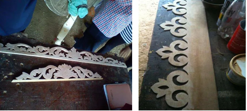
sculptural is jigsaw, driller, and grinder. The wood sculptural produce by Mr. Mustazarin is more on decorations for building (which used to hang on the wall), wooden boxes, and small cupboards. Figure 1.1 shows the wood carving products which made by Mr. Mustazarin.
Figure 1.1: Wood carving product which used to decorate fence or staircase
There are three types of materials used to produce the products. They are Meranti (Merah and Putih) – Shorea sp., Mersawa – Anisoptera grossivenia sp., and plywood. Each wood are with different thickness: Meranti (1 cm – 2 cm), Mersawa (1.8 cm – 1.9 cm), and plywood (3 mm, 5mm, and 9 mm). Each type of wood will then used for different profiling.
4
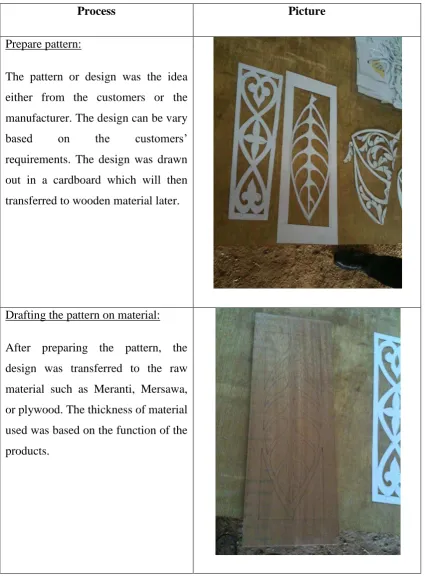
Table 1.1: Steps for manually or conventional wood carving process
Process Picture
Prepare pattern:
The pattern or design was the idea either from the customers or the manufacturer. The design can be vary
based on the customers‟
requirements. The design was drawn out in a cardboard which will then transferred to wooden material later.
5 Drilling:
Drilling was used to create a starting point for profiling. This is because the carving pattern was with the hollow parts in the centre of the wood. After drilled a hole, the blade can insert through the hole and start for the profiling process.
Profiling: