accredited by DGHE (DIKTI), Decree No: 51/Dikti/Kep/2010 555
An Approach to Minimising Estimated Pincushion
Camera Distortions
Folorunso Olufemi Ayinde*1, Mohd Shahrizal Sunar2, Adekiigbe Adebanjo3, Obasan Olukayode4
UTMVicubeLab, Department of Computer Graphics and Multimedia, Universiti Teknologi Malaysia, 81310 Skudai, Malaysia
e-mail: [email protected],[email protected], [email protected], [email protected]
Abstrak
Peminimalan distorsi kamera akhir-akhir ini telah menjadi fokus penelitian photorealism. Dari beberapa jenis distorsi kamera, peneliti berkonsentrasi pada distorsi radial yang menjadi bagian paling parah pada penyimpangan lensa. Seringkali, aproksimasi polinomial dengan memperkenalkan parameter distorsi- khusus ke dalam model kamera dijadikan metode evaluasi distorsi. Dari dua jenis distorsi radial, barel, adalah yang paling mungkin dibicarakan karena dominasinya di lensa sudut-lebar yang murah. Pada makalah ini diusulkan sebuah pendekatan untuk mengestimasi dan meminimalkan distorsi bantalan dengan menggunakan sifat area permukaan dasar dari gambar terdistorsi. Makalah ini mengungkapkan secara signifikan pentingnya topik dan implikasinya pada kamera. Demonstrasi menggunakan empat lensa kamera menunjukkan kekokohan dari teknik ini pada kondisi panjang focal yang berbeda. Keandalan dari pendekatan ini dibuktikan dengan membandingkan hasil dengan pengamatan fisik menggunakan uji statistik t-test (dua sisi).
Kata kunci: Distortion centre, image geometry, pincushion distortion, Surface area, lens aberration
Abstract
Minimizing camera distortion has been a focus of recent photorealism researches. Of the several types of camera distortions, researchers concentrated on the radial distortion being the most severe part of the total lens aberrations. Often, polynomial approximations by introducing distortion-specific parameters into the camera model have been methods of evaluating distortions. Of the two types of radial distortions, barrel, is the most discussed probably because of its dominance in cheap wide-angle lenses. In this paper, an approach to estimating and minimizing pincushion distortion by using fundamental surface area properties of the distorted image is proposed. This paper is significant as it reveals the importance of the topic and its implications on the camera. Demonstrations using four camera lenses show the robustness of this technique under different focal lengths conditions. The reliability of the approach is justified by comparing the results with the physical observations using (two tailed) t-test statistic.
Keywords: camera, image geometry, pincushion distortion, surface area, lens aberration
1. Introduction
An augmented reality system must be structured to combine both the real and the virtual world, provide interactivity in real time and registration in 3D [1],[2]. For effective 3D registration, distortions estimation and minimization are crucial factors [3]. The radial distortions have been viewed as inherent errors of any lens [4], although some scholars including [5] have attributed this to design and or manufacturing errors.
of the image is affected by either an increase or a decrease. The visual effect of pincushion distortions and barrel distortions on image geometry is illustrated in Figures 1 and 2.
Figure 1. (a) Showing effect of negative and (b) positive pincushion distortion on images. The dashed line represents the actual image without any distortion.
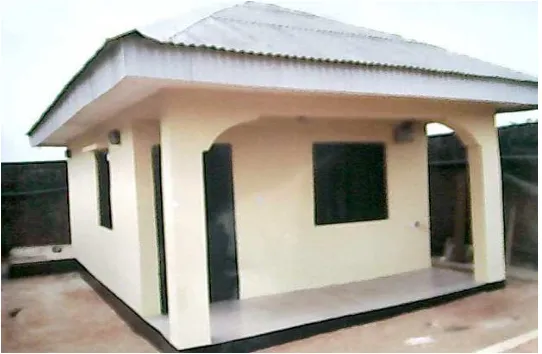
Figure 2. Showing effect of pincushion distortion on an image slightly corrected +6.0.
*Fig. 2 Images source: EFVI Derivatives, Lagos
Modern digital cameras with zoom lenses are often the victims of this type of lens aberrations. In some researches including [1], [6], [7], pincushion distortion has been estimated as the amount a reference line is bent to the percentage of the image height. Most consumer digital cameras retain a pincushion distortion much lower than that of the barrel distortion with 0.62% being a typical value [5].
Applications areas such as the augmented reality (AR) rely heavily on the correctness of camera‘s positioning (both real and virtual). For obvious reasons of misalignments, repeated calibration has often been an approach to reducing overall camera aberrations. This approach has been found daunting due to much human-involvement which is disadvantageous for automated applications where time is a factor [10]. In literatures, two methods are common for calibrating cameras lenses more efficiently: (1) the camera self-calibration method by [10] and (2) the Dynamic camera self-calibration from controlled motion sequences by [11]. Camera calibration is performed by observing an object whose geometry in 3D space is known. The calibration objects are orthogonally placed planar objects.
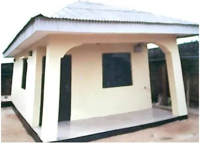
Like any other types of distortions, pincushion distortions are quite difficult to notice in photography except when the camera is used to capture a building or a horizon with straight lines or edges as shown in Figure 2. Some image manipulating software like the Photo-Brush is often employed to handle pincushion distortions using high quality bi-cubic interpolations integrated into its program logic. The output is often a high-quality image without “any” traces of manipulation as shown in Figure 11. The limitation of this however is the rigidity of its application and inapplicability to all types of pincushion distortions. In addition, estimation of pincushion distortion is a neglected issue in those applications and recent researches [3], [9], [11]. Therefore, the understanding of the digital camera pincushion distortion estimation and minimization is a significant topic in photography and photorealistic researches. This paper is significant as it reveals the importance of the topic and its implications on the camera as a device.
2. Research Method
We propose a mathematical model for pincushion distortions based on the geometric view area (of the image) as captured by the camera lens. The model does not incorporate the use of either the intrinsic or the extrinsic camera parameters. The approach is most useful where minimisation of pincushion effects is desired especially in viewing of horizons and buildings that have straight boundaries and lines. A basic assumption in this paper is that the planar object is squared. This paper is organised thus: First, a model for estimating the total area of an image and the total area affected by pincushion distortions as a way of estimating them is presented. This is followed by the generalised cameral model which was expanded to encompass the geometrical based pincushion distortion. A mathematical approach for estimating pincushion distortion using the derived function is developed lastly some examples to validate the robustness of the proposed technique are presented.
2.1 Pincushion Distortion Model
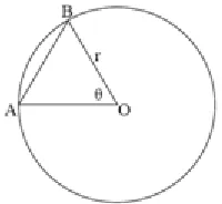
Basic Assumption: Assuming that the image under consideration is planar and squared. The modelling of pincushion distortion is achieved by the understanding of the area covered by a minor segment AB of a circle centre O radius r and angle θ as shown in Figure 3.
Figure 3. Showing circle centre O radius r and angle θ.
By definition, the area of segment AB denoted henceforth as (sAB) equals the area of sector AOB minus the area of triangle AOB, that is,
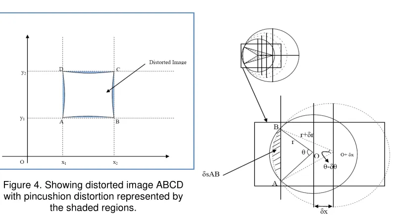
Since the image is assumed planar on the x-y plane, (say): Assuming coordinates A(x1,y1), B(x2,y1), (x2,y2), D(x1,y2), for the image vertices as shown in Figure 4. The area covered by the distorted image (dIA) is thus:
݀ܫܣ= (xଶ− xଵ)ଶ−ݎଶ(0.03492θ − 2ݏ݅݊θ) (3)
Figure 4. Showing distorted image ABCD with pincushion distortion represented by
the shaded regions.
Figure 5. Showing changing distortion areas
δsAB as r and θ changes.
Figure 6. Showing the distorted image and the distortion areas generated by varying θ
and r.
2.2 The Camera Model
The modelling follows the conventional relationship between a 3D point Pi and its projection image pj described by [4] as:
ߙ=ܫሾܧሿܲ݅ (4)
Where α is non-zero arbitrary scale factor, I and E are the intrinsic matrix and the extrinsic parameters respectively. Camera intrinsic matrix I is given as:
ܣ=൭ܽ ߣ ݔ0 ܾ ݕ
0 0 1
where x and y are coordinates of the image‘s principal point, a and b are the scale factors in image x and y axes, and λ is the skewness of the two image axes. Camera extrinsic parameter E is the rotation and translation matrices which relate the world coordinate system to the camera coordinate system often denoted by:
ܧ=ܴ| −ܴݐ (6)
In all, six parameters must be estimated, 3 intrinsic and 3 extrinsic. The extrinsic parameters could be estimated using method described by [3]. This method provided solution through minimizing an algebraic distance which is described as “physically meaningless” but was refined by using the maximum likelihood inference. The maximum likelihood estimate was obtained by minimizing a nonlinear minimization problem, which was solved with the Levenberg-Marquardt Algorithm. The algorithm is well described and implemented by [1], [6], [12], [14].
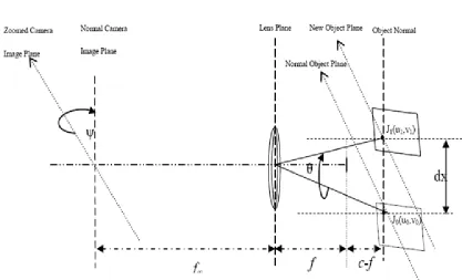
During calibration, either the camera or the planar object is rotated, or translated or both which creates the distortion. For most practical applications λ- the skewness, is zero, simply because the planar object is placed on (say) a table. In this research, a slightly different view from this is upheld by assuming that an arbitrary point J0(u0,v0) in the planar image is shifted from z=0 to z=dx in 3D (object space) to J1(u1,v1), sweeping the lens‘ view through angle θ as shown in Figure 7. Where f and f∞ are the focal lengths of the camera lens and image, c is a parameter local to the camera mapping function, and ψ is the zooming angle. By applying the geometric relation assumption proposed by [5], it follows that:
݀ݔ=ܿ∗ݏ݅݊θ (7)
Figure 7. Showing geometric relationships based on the assumptions
For ease of computations, c could be approximated to be equivalent to the focal length of the camera.. Since logట→±ట(ܿ−݂) = 0 and any arbitrary point Pi(xi,yi) in the planar coordinates and the corresponding point pj(xj,yj) in the virtual image must satisfy the model described in equation (4), and because the camera and the planar object are no longer perpendicular to each other relative to the z axis, it follows that the skewness of the two image axes λ = λ+cα, where α is a constant of displacement. By placing the camera lens at a chosen distance far away from the image plane such that f∞ >>> f, It follows therefore from (4) that:
ߙ=൭
Polynomial approximation has been a preferred method for modelling radial distortions. It is often expressed as [8]: distortions, second or forth order d is sufficient [1],[6],[8]. The proposal for pincushion distortions therefore is:
u = d(u୧,k)
(10c)
with d = rଶ(0.03492Ѳ − 2sinѲ) (10d)
Where θ is the angle (in degrees) swept by the camera lens from point J0(u0,v0) to J1(u1,v1) through distance dx as shown in Figure 6. r is the image distortion radius.
2.4 Estimating Pincushion Distortions
Since ψ is the zooming angle of the camera, it is obvious that the zoomed camera image plane, the normal object plane and the new object plane (from Figure 7) are parallel. By using the frequently used model of camera perspective it follows that:
tanψ =ୢ୶
(11)
or ߰=ݐܽ݊ିଵ ௗ௫
Now, since the desired image should be pincushion-distortion free, it follows that:
In the neighbourhood of rr++ (or when r is ‘reasonably large’) as a result of increased zooming angle, the image is distortion free. The same results can be obtained by reducing the zooming angle. Since dx is a constant and f is known, this makes the computation (of the tPD) very easy. When compared to a similar research by [1], [5], [16] this pincushion distortion estimate is entirely a function of only the focal length of the camera.
3. Results and Discussion
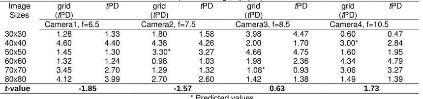
To validate the propositions above, the null hypothesis is stated thus: There is no significant difference between the pincushion distortion obtained from practical and theoretical estimates using (14). Pincushion distortions were estimated by using four cameras lenses with focal lengths (6.5mm, 7.5mm, 8.5mm, 10.5mm) and six objects with dimension (30x30)mm2,(40x40)mm2, (50x50)mm2, (60x60)mm2, (70x70)mm2 and (80x80)mm2. Each of the cameras lenses are used to capture images of the objects by moving the lens through distances dx= {40mm, 50mm, 60mm, 70mm and 80mm} corresponding to the length of each object (as illustrated in Figure 6). The images are printed out using HP DeskJet F4280 printer and placed on pre-printed square grids (of 1mm-squared) dimensions. The pincushion distortions on the images were estimated using the square grids denoted by grid(tPD). Theoretically the tPD described in this paper was also calculated for each view of the objects by each of the cameras using their focal lengths described in (14).
The pincushion distortions estimates obtained from both the grid-based and the theoretical (with (14)) are compared using a repeated-measure t-test statistic as shown in Table 1. The obtained t-values are not extremely high enough to fall in the critical region (±2.571). The t-distribution table is consulted for a two-tailed test with significance level α = 0.05, df = 5.
Therefore, we fail to reject the null hypothesis and conclude that there is no significant difference between the two sets of data. The theoretically determined results using (14) are easier to compute, it is therefore suggested for future use in estimation of pincushion distortions.
Table 1. Pincushion distortions estimates in (mm2) obtained from the practical (grid-based estimate) and using eq. (14).
Camera1, f=6.5 Camera2, f=7.5 Camera3, f=8.5 Camera4, f=10.5 30x30 1.28 1.33 1.80 1.58 3.98 4.47 0.60 0.47
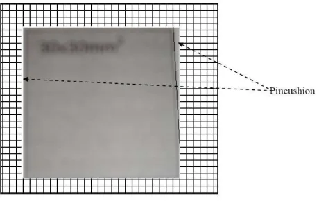
captured and printed images is superimposed on a uniformly ordered 1mm2 tiles grid as shown in Figure 10. In an example with camera lens focal point f = 6.5, only 0.32 cells are within the distortion on each side of the superimposed squared image for the (30x30) mm2.
Figure 8. Showing bar chart for distortions obtained (y-axis) with both methods using Camera1 lens.
Figure 9. Showing t-value progression with changing and increasing camera focal lengths.
Therefore, grid( tPD) = 0.32*4 = 1.28mm2. Figure 11 shows an example of image with distortion removed.
Figure 11. Showing effect on image geometry after removing distortions (Images source: EFVI Derivatives, Lagos)
For ease of computation, only one side is determined and multiplied by 4 since the pincushion distortion obviously affects all the four edges. Pincushion distortion at one of the edges is sufficient to estimate the total for the whole image; visual variances observed at any other edges are largely due to ignorable human errors that gives pointers to more researches in the near future.
4. Conclusion
This paper presents an approach to estimating and minimizing pincushion distortion by making using fundamental surface area properties of the distorted images. It reveals the importance of the topic and its implications on the camera. The experimental results obtained from four camera lenses shows the robustness of this technique under different focal lengths conditions. The reliability of the approach is justified by comparing the results with the physical observations using (two tailed) t-test statistic.
Acknowledgements
Support for this research was received from the Yaba College of Technology, Lagos, Vi-CubeLab research group, Faculty of Computer Science and Information Systems, Universiti Teknologi Malaysia and Obasan Kayode, EFVI Derivatives, Lagos for help rendered in performing repeated camera calibrations for the purpose of the examples described in this paper. Finally, appreciation also goes to the Universiti Teknologi Malaysia for providing necessary atmosphere for the research.
References
[1] Carlos Ricolfe-Viala and Antonio-Jose Sanchez-Salmeron. Lens distortion models evaluation. Applied Optics. 2010; 49(30): 5914-5928.
[2] Ronald T. Azuma. A Survey of Augmented Reality. In Presence: Teleoperators and Virtual Environments. 1997; 6(4): 355-385.
[3] Zhang Z. A Flexible New Technique for Camera Calibration. Microsoft Research. Microsoft Corporation. December, 1998.
[5] Perš J, ovaˇciˇcS. K. Nonparametric, Model-Based Radial Lens Distortion Correction Using Tilted Camera Assumption. Proceedings of the Computer Vision Winter Workshop. Bad Aussee, Austria. 2002: 286–295
[6] Jiang L. Precision grating for measuring microscope lens distortions. International Journal of Metrol. Qual. Eng. 2010; 1(2): 83-88
[7] Sobolewski VC. Using moiré patterns to determine the distortion of graphics displays and graphics input devices. Proceedings of the IEEE. 1970; 58(4): 567-576.
[8] Tsai RY. A versatile camera calibration technique for high- accuracy 3D machine vision metrology using off-the-shelf TV cameras and lenses. IEEE Journal of Robotics and Automation. 1987; RA-3(4): 323-334.
[9] Zhengyou Z. The epipolar geometry between two images with lens distortion. In proceedings of International Conference on Pattern Recognition. 1996: 407-411.
[10] Abdullah J. & Martinez. Camera Self – Calibration for ARToolkit. 2002.
[11] Dron L. Dynamic Camera Self Calibration from Controlled Motion Sequences. In proceedings of IEEE Conference on Computer Vision and Pattern Recognition. 1993: 501-506.
[12] More J. The levenberg-marquardt algorithm, implementation and theory. In G. A.Watson, editor,
Numerical Analysis, Lecture Notes in Mathematics 630. Springer-Verlag. 1977.
[13] Levenberg K. A Method for the Solution of Certain Non-linear Problems in Least Squares. Quarterly of Applied Mathematics. 1944; 2(2): 164–168.
[14] Lampton M. Damping-Undamping Strategies for the Levenberg-Marquardt Nonlinear Least-Squares Method. Computers in Physics Journal. 1997; 11(1): 110–115.
[15] Folorunso OA, Mohd S, Ikotun AM. Augmented Reality Prototype for Visualising Large Sensors’ Datasets. TELKOMNIKA Indonesian Journal of Electrical Engineering. 2011; 9(1): 161-170