DOI: 10.12928/TELKOMNIKA.v15i2.4981 560
Low-Cost Contact Angle Measurement System for QCM
Sensor
Setyawan P. Sakti*, Rizal Y. Aji, Layli Amaliya, Masruroh
Department of Physics, Brawijaya University, Jl Veteran, Malang 65145, INDONESIA *Corresponding author, e-mail: [email protected]
Abstract
Hydrophobicity is one of the importance factors in the surface properties of materials. This work presents the development of a low-cost contact angle measurement system based on goniometric measurement using an inexpensive digital camera, tilt control system for surface alignment and curvature approximation algorithm to determine the contact angle between the solid and spherical cap of a water droplet. The design is specifically targeted for measuring the contact angle of a Quartz Crystal Microbalance sensor in the form of HC-49/U with a disc diameter of 8.7mm.The contact angle measurement using goniometric measurement depends on the quality of captured image and calculation method for the angle determination. Proper alignment of the sample surface is required to minimize the discrepancy of the angle measurement of water drop surface profile caused by gravity. A PIC18F4550 microcontroller is used to control the motorized tilt platform to reduce the gap between left and right contact angle value. Circle fit algorithm to determine the contact angle value from the captured image is used. Using the motorized tilt control system and circle fit algorithm, the developed contact angle measurement system able to measure the contact angle with discrepancy less than 1O.
Keywords: contact angle, motorized tilt control, goniometric, QCM
Copyright © 2017 Universitas Ahmad Dahlan. All rights reserved.
1. Introduction
Hydrophobicity is one from many importance factors of surface properties. Studies on the material surface properties related to the hydrophobicity can be found in many research work until now. The hydrophobicity of the surface not only attractive for the large surface study but also in the nanotechnology development. Nanostructuring to manipulate the surface hydrophobicity is still in progress in many studies [1-4].
Hydrophobicity plays an importance role in the interaction of materials, macromolecules folding, protein folding, protein-protein recognition, surface wetting, and many other process and mechanism. In the development of quartz crystal microbalance (QCM sensor), hydrophobicity affects biomolecule immobilization on the sensor surface. Hydrophobicity is one importance factor on the adsorption and orientation of antibody on the surface [5]. Physical adsorption of biomolecules on a solid surface, where hydrophobicity plays an importance role is widely known [6-7]. Physical adsorption, for example, is also used in the QCM immunosensor, where the antibody immobilized on top of polystyrene surface [8]. Sequence-specific DNA immobilization on a glass carbon electrode is also able to be done by physical adsorption [9].
However, a smaller water droplet will evaporate in a short time so that the image capture should be done as quickly as possible. Contact angle calculation is based on the drop shape method [10] and others [11-14].
Larger water droplet can affect the profile of the water droplet caused by the gravitational force. The water droplet is flattened in the center. Also, a larger water droplet can also cause difficulties in the measurement due to the alignment of the sample surface to the camera. This method requires a condition that the sample surface must be perpendicular to the gravitation force direction, or it must be in a horizontal direction about the earth surface. For a flat specimen, putting the sample surface horizontal is not difficult. This case is not easy for irregular shape or a geometry shape where horizontal surface sample placement is challenging. Hysteresis may also occur in the contact angle measurement caused by many factors [15]. The particular approach needs to be taken when the solid surface is convex or concave shape [16].
QCM sensor made from a commercial quartz resonator in the form of HC49/U has a quartz disc placed in a holder with electrical leads. This mechanical construction makes additional constraints in the contact angle measurement of the sensor surface. The quartz surface, unfortunately, is not always well aligned with the holder. Two sides of the sensor disc are not perfectly planar surface. When the water droplet is larger, the water droplet geometry is asymmetric caused by gravitational force. The gravitational force makes water contact angle on the right side, and the left side of the measured image is not equal. The difference results in an inaccuracy of the contact angle measurement.
Therefore, it is importance to have a system where the sliding angle of the QCM sensor surface can be eliminated by adjusting the surface angle about the gravitational force before the water droplet is put on the surface. Further alignment can be done after putting the water droplet on the sample surface. A motorized tilt platform control system is required to adjust the horizontal alignment smoothly. This work presents the development of a low-cost contact angle measurement system. The proposed system has a tilt control system to make the system works for various shapes of the sample not limited to a flat sheet sample only. The developed system consists of a low-cost digital camera, motorized tilt platform system, and contact angle calculation software.
2. Method and Procedure
The system development is done by developing the hardware and software system. The hardware of the system consists of motor stepper control for the tilt platform and image capture. The software system consists of motor stepper control, image capture and contact angle calculation based on the captured water drop image.
Calibration for the tilt platform is done to get the speed and resolution of the tilt platform at different stepper motor step movement. Calibration and calculation are done by capturing the plate image of the tilt platform. The resulting line image of the tilt platform surface is then calibrated to a horizontal image line. Maximum resolution of the tilt angle platform is taken from the gradient of the platform angle to the motor stepper movement at quarter step mode.
The following procedure is used for the contact angle measurement of the QCM sensor sample. At first, the sensor is placed in the sensor holder on top of the tilt platform. The tilt platform angle is adjusted until the sensor surface aligned horizontally. A 30µL distilled water was dropped on top of the sensor surface. The droplet image was captured using the image capturing software integrated into the tilt platform control. The resulting black and white image are then passed to the contact angle calculation program.
3. Result and Discussion 3.1. Contact Angle Calculation
program is required to calculate the best approximate circle of the water drop. The calculation is done using circle fit method function developed by Izhak Bucher [17] in Matlab program.
The drop shape method is calculated based on the assumption that the water drop forms a perfectly spherical cap. This assumption is only good for a small water drop [10]. Calculation using the assumption of an ideal sphere is valid for the maximal volume of 10µL with a surface contact angle between 10 and 140 [14, 18]. For a big water drop, the shape does not form an ideal spherical cap caused by the gravitational force and also a sliding surface. In this work, we calculated the contact angle by assuming two different spherical caps. One is a spherical cap for the left side and another one on the right side of the drop shape. As described before, the alignment of the sensor surface is not horizontal, and the sensor surface not always flat. Therefore the program is modified to fit the drop shape image as two circles. One circle is calculated for the left contact angle and the other one to calculate the right contact angle.
(a) (b)
Figure 1. Drop shape model for acute angle (a) and obtuse angle (b)
(1)
(2)
3.2. Image Capture Sub-System
The low-cost digital camera has been used for many application based on image capture system [19, 20]. A digital camera used in a digital microscope has a built-in image processing to for contrast and brightness to get the best droplet image [21]. For some application, the resolution and In this design, a low-cost digital microscope camera is used to capture the droplet image. The camera has a CMOS sensor with a maximum physical resolution of 2M-Pixel and magnification ratio of 50 to 500 times. Focus length of the camera is 3mm to 40 mm. Maximum resolution of the digital camera is 1600x1200 pixels. This low-cost digital camera is commonly used as a camera for a low-cost digital microscope or digital inspection system. The camera system can capture a live video with a speed of 30 frames per seconds. This speed is adequate to capture the image of the liquid drop on top of the sensor surface. The digital camera and the personal computer are connected via USB data communication.
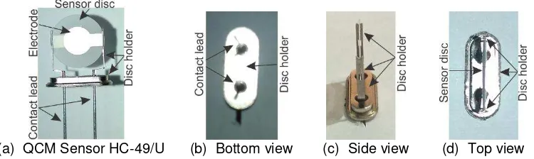
(a) QCM Sensor HC-49/U (b) Bottom view (c) Side view (d) Top view
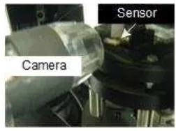
Figure 3. Sensor and camera position
The resonator disc and holder design of the QCM sensor (made from HC-49/U resonator) limit the position between the digital camera and the sensor. Figure 2 shows the perspective view of the QCM sensor to be measured. The base metal of the resonator disc holder blocks the disc view from the bottom (Figure 2b). The lead contact also prevents the view from the left and right side of the disc (Figure 2c). The only possible view is from the top of the sensor disc (Figure 2d). Therefore the position of the camera should be placed from the top view of the sensor.
Figure 3 shows the position of the camera to capture the droplet image and sensor. The sensor is fitted horizontally. The camera is placed inline with the sensor disc surface to get the droplet image from the top view of the sensor disc. The distance of the sensor to the camera is arranged in the range of focal length of the low-cost digital microscope.
3.3. Tilt control
The position of the sensor disc in the sensor holder is not always perfectly aligned. This misalignment results in a sliding surface of the sensor disc. Sliding sample surface may result in contact angle measurement error because of the discrepancy of the water droplet contact angle between the right part and left part. Figure 4 shows a figurative condition of a water droplet on top of a solid surface. When a water droplet is placed on top of a solid surface, the surface profile of the water droplet forms a spherical cap, depends on the surface hydrophobicity of the solid surface. If the solid surface is perfectly flat and perpendicular to the gravitational force, the spherical cap of the water droplet is symmetric.
(a) (b)
Figure 4. Water droplet on a horizontal surface (a) and a sliding surface (b)
Figure 4(a) shows an illustration of a water droplet on a solid surface perpendicular to the gravitational force direction. The contact angle of the left side (L) and right side (R) is equal. When the surface position makes an angle (S) with the horizontal, the left angle and right angle is unequal. The water droplet profile is skewed as in Figure 4(b). This inequality results in the accuracy of the contact angle measurement. Many samples, however, not always in the form of a flat sheet.
angle to the horizontal surface. Turning the stepper motor to the right direction moves the stroke upward, and turning the stepper motor to the left moves the stroke downward.
The stepper motor is driven using IC DRV8825 stepper motor controller from Texas Instruments. The controller has two H-bridge driver and micro stepping indexer. Each driver can deliver a maximum of 2.5A current. The specification is adequate to be used as a controller for the LSDQ-5S2.
Figure 5. Technical drawing and photograph of the two-axis motorized tilt platform LSDQ-5S2
3.4. Overall System Design and User Interface
Block diagram of the system is depicted in Figure 6, and the photograph of the developed system is presented in Figure 7. It can be seen that the position of the sensor is in front of the camera. The main part of the system consists of a mechanical part for QCM sensor surface alignment, image capture subsystem, and contact angle calculation program and software interface. The connection of the image capture subsystem and the microcontroller to the computer is made via USB communication to minimize the cable connection. The mechanical sub-system is responsible for the surface alignment of the sensor. Motion control of the motor driver of the stepper motor for the tilt stage is done by using a PIC 18F4550. The digital camera as the core of the image capture subsystem transfers the image to the image capture program and the contact angle calculation program via the digital camera driver provided by the manufacturer.
Figure 6. Block diagram of the system Figure 7. Photograph of the system
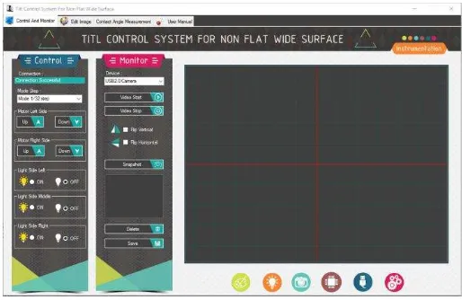
user interface is tilt platform control in the left part and water drop image area in the right part of the graphical user interface.
The software sends a command to the tilt platform via USB interface. Tilt adjustment selects the axis (left or right axis), controls the speed and direction of movement. The image capture software shows the horizontal alignment of the sensor visually. The command is sent to the PIC18F4550 which then translate the command to control the movement of the tilt platform axis.
Figure 8. User interface of the contact angle measurement system
3.5. Tilt Platform Resolution and Contact Angle Measurement
Successful horizontal alignment is a key factor in the contact angle measurement using the drop shape method for a water drop more than 10µL. Therefore the tilt angle control is importance. Angle change caused by the stepper motor movement needs to be known. Angle change caused by the stepping angle of the motor stepper was measured to know the lowest change to align the sensor surface. The measurement was conducted for stepping control of full step, half step and quarter step.
Figure 8 to 10 shows the tilt angle change of the tilt platform for each step movement. The angle change of the tilt platform has a linear relation with the motor stepper movement. This linear relationship makes an effort to control the tilt platform in a horizontal alignment easier. The graphs show that the left stroke and right stroke movement does not exactly result in the same angle change of the tilt platform. For the full step (Figure 8), the gradient of the left angle change is 0.1262 and for the right angle is 0.1119. Thus every single step of the motor stepper in full step mode changes the left angle of 0.1262 and right angle of 0.1119. Maximum tilts angle 5 as in the datasheet specification of the LSDQ-5S2 is reached after 40 full step.
Finest stepping movement results in smaller gradient. For the quarter step movement, each step caused a change in the tilt angle of 0.0325 for the left angle and 0.0330 for the right angle as presented in Figure 11. It means that we can obtain the smallest angle change to align the platform surface, hence the sensor surface, horizontally is 0.03 by using quarter step movement. Theoretically, a single step of full step movement equals to four steps of quarter step. Angle change caused by a full step movement should be equal to four times of the quarter step. The result of the experiment is lower than expected. The full step angle change is 3.9 and 3.6 times of the quarter step one.
captured and further processed by contact angle calculation program. Figure 12 shows an example of captured water droplet image in the contact angle calculation program.
Figure 9. Tilt angle change caused by full step movement
Figure 10. Tilt angle change caused by half step movement
Figure 11. Tilt angle change caused by quarter step movement
Theoretically, the right angle and left angle of the measurement should be equal. Determination of contact angle is assuming no discrepancy in the contact angle measurement of the droplet. Therefore, only one value of contact angle is determined. In our experiment, the circle fitting program calculates the contact angle on the left side of the spherical cap image and right side contact angle. Circle fitting is done separately by taking a fraction of the spherical cap image on the left side for the left side contact angle and fraction of the spherical cap image on the right side for the right side contact angle.
On the successful calculation, the program draws a resulted circle model on the image. Figure 12 shows a green line circle on top of the droplet image. The circle is drawn based on the resulted data from the fitting program. Because of the small different in the contact angle value, the fitting circle from the left side contact angle overlaps with the fitting circle from the right side contact angle. Figure 13 shows a resulted calculation and fitting from a droplet image which has noticeable different contact angle on the left side and right side. The fitting circle line left angle is drawn with the yellow line and the right side contact angle with the green line.
Figure 12. Overlaid circle drawing on droplet image has a same fitted circle for the right part
image and left part image of the droplet
Figure 13. Droplet image with different fitted circle on the right part image and left part
image of the droplet
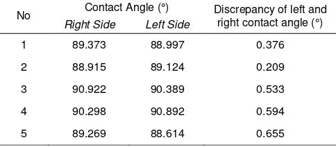
The resulted contact angle measurement is presented in Table 1. The contact angle value is close to 90. Although the sensor surface has been aligned horizontally, the resulting contact angle measurement results in a discrepancy between the contact angle of the left side image and contact angle on the right side image. The different between two contact angles is less than 1%.
Following to the measurement of the contact angle, the sensor with polystyrene coating was heated in an oven at a heating temperature of 100C. The contact angle measurement of the water droplet image is presented in Table 2. Based on the measurement value, it can be seen that the contact angle of the sensor is larger than 90. The discrepancy between the left side and right side image is less than 0.5.
Ultraviolet radiation alters the surface property of polystyrene. The mechanism involves photo-oxidation and breakdown of polymeric C–C bonds [23]. UV radiation makes the polystyrene surface to be more hydrophilic as reported in [24, 25]. The UV radiation method is used to produce a hydrophilic surface for this experiments. The sensor with polystyrene surface is irradiated using UV with a wavelength of 254nm for 1 hour. The contact angle of the sensor surface is then measured using the system. The contact angle value is presented in Table 3. The contact angle of the polystyrene surface after UV irradiation is less than 90°.
Table 1. Difference contact angle value between the left side and right side of a surface with a contact angle close to 90O
No Contact Angle (°) Discrepancy of left and right contact angle (°)
Right Side Left Side
1 89.373 88.997 0.376
2 88.915 89.124 0.209
3 90.922 90.389 0.533
4 90.298 90.892 0.594
5 89.269 88.614 0.655
Table 2. Difference contact angle value between the left side and right side of a surface with a contact angle > 90O
No Contact Angle (°) Discrepancy of left and right contact angle (°)
Table 3. Difference contact angle value between the left side and right side of a surface with a contact angle < 90O
No Contact Angle (°) Discrepancy of left and right contact angle (°)
The low-cost contact angle measurement with tilt control has been successfully developed using a low-cost digital microscope camera. The resolution of the tilt platform angle adjustment is 0.03 at quarter step movement of the stepper motor. Contact angle measurement the QCM sensor with different polystyrene can be done using the developed system. The resulted contact angle of a water drop with a volume of 30mL still has a small contact angle discrepancy between the left side and right side contact angle. The discrepancy of the contact angle between the left side and right side of the water droplet is less than 1. Improvement for the proposed low-cost contact angle measurement system can be made by implementing automatic tilt alignment of the sample.
Acknowledgements
This work is supported by Ministry of Research, Technology and Higher Education of the Republic of Indonesia under the PUPT Brawijaya University scheme project.
References
[1] Wang F, Wu H. Molecular origin of contact line stick-slip motion during droplet evaporation. Scientific
Reports. 2015; 5: 17521.
[2] Bonn D, Eggers J, Indekeu J, Meunier J, Rolley E. Wetting and spreading. Reviews of Modern
Physics. 2009; 81(2): 739-805.
[3] Gharabaghi M, Aghazadeh S. A review of the role of wetting and spreading phenomena on the flotation practice. Current Opinion in Colloid and Interface Science. 2014; 19(4): 266-282.
[4] Maestro A, Guzmán E, Ortega F, Rubio RG. The contact angle of micro- and nanoparticles at fluid interfaces. Current Opinion in Colloid & Interface Science. 2014; 19(4): 355-367.
[5] Wiseman ME, Frank CW. Antibody Adsorption and Orientation on Hydrophobic Surfaces. Langmuir. 2012; 28(3): 1765-1774.
[6] Bhakta SA, Evans E, Benavidez TE, Garcia CD. Protein adsorption onto nanomaterials for the development of biosensors and analytical devices: A review. Analytica Chimica Acta. 2015; 872: 7-25.
[8] Sakti SP, Wahyuni F, Juswono UP, Aulanni’am. Development of QCM immunosensor with small sample solution for detection of MMP-3 antibody. Sensors and Transducers. 2013; 149(2): 143-148. [9] Cai H, Wang Y, He P, Fang Y. Electrochemical detection of DNA hybridization based on
silver-enhanced gold nanoparticle label. Analytica Chimica Acta. 2002; 469(2): 165-172.
[10] Yuan Y, Lee TR. Contact Angle and Wetting Properties. In: Bracco G, Holst B. Editors. Springer Series in Surface Sciences. Berlin, Heidelberg: Springer Berlin Heidelberg; 2013).
[11] Xu Z. An inclined plane based dynamic contact angle algorithm and its validity in application of hydrophobicity measurement for insulating materials. IEEE Transactions on Dielectrics and Electrical
Insulation. 2013; 20(5): 1832-1835.
[12] Dimitrov AS, Kralchevsky PA, Nikolov AD, Noshi H, Matsumoto M. Contact angle measurements with sessile drops and bubbles. Journal of Colloid And Interface Science. 1991; 145(1): 279-282.
[13] Fu H, Liu J, Yang T, Li S. Research on Fast Low-Cost Measurement of Contact Angle Surface
Tension and Viscosity. 2015 International Conference on Fluid Power and Mechatronics. 2015:
691-695.
[14] Gu H, Wang C, Gong S, Mei Y, Li H, et al. Investigation on contact angle measurement methods and wettability transition of porous surfaces. Surface and Coatings Technology. 2016; 292: 72-77. [15] Eral HB, ’t Mannetje DJCM, Oh JM. Contact angle hysteresis: a review of fundamentals and
applications. Colloid and Polymer Science. 2013; 291(2): 247-260.
[16] Wu D, Wang P, Wu P, Yang Q, Liu F, et al. Determination of contact angle of droplet on convex and concave spherical surfaces. Chemical Physics. 2015; 457(1): 63-69.
[17] Bucher I. Circle Fit: circfit.m. Mathworks. 2004.
[18] Extrand CW, Moon SI. When Sessile Drops Are No Longer Small: Transitions from Spherical to Fully Flattened. Langmuir. 2010; 26(14): 11815-11822.
[19] Putra IKGD, Cahyawan A, Perdana Y. Low-Cost Based Eye Tracking and Eye Gaze Estimation.
Telkomnika. 2011; 9(2).
[20] Fadlil A. An Automatic Identification System of Human Skin Irritation. Telkomnika. 2010; 8(3): 255-264.
[21] Hartati S, Harjoko A, Supardi TW. The Digital Microscope and Its Image Processing Utility.
Telkomnika. 2011; 9(3): 565-574.
[22] Sakti SP, Rahmawati E, Robiandi F. Solvent effect on polystyrene surface roughness on top of QCM sensor. The 4th International Conference on Theoretical and Applied Physics (ICTAP) 2014. 2016; 30017: 30017.
[23] Yousif E, Haddad R. Photodegradation and photostabilization of polymers, especially polystyrene: review. SpringerPlus. 2013; 2(1): 1-32.
[24] Zhang D, Dougal SM, Yeganeh MS. Effects of UV irradiation and plasma treatment on a polystyrene surface studied by IR-visible sum frequency generation spectroscopy. Langmuir. 2000; 16(10): 4528-4532.
[25] Jaleh B, Shayegani Madad M, Farshchi Tabrizi M, Habibi S, Golbedaghi R, et al. UV-Degradation Effect on Optical and Surface Properties of Polystyrene-TiO2 Nanocomposite Film. Journal of the