ISSN: 1693-6930
accredited by DGHE (DIKTI), Decree No: 51/Dikti/Kep/2010 695
Optimal Design of Fuel-cell, Wind and Micro-hydro
Hybrid System using Genetic Algorithm
Soedibyo, Heri Suryoatmojo, Imam Robandi, Mochamad Ashari
Department of Electrical Engineering, Sepuluh Nopember Institute of Technology (ITS) Sukolilo, Surabaya, (60111), Indonesia, Telp: 031 5947302
e-mail: [email protected]
Abstrak
Target dari sistem hibrida yang beroperasi mandiri adalah untuk mensuplai beban dengan reliability yang tinggi dan ekonomis. Sebuah teknik optimasi menggunakan kecerdasan buatan diperlukan untuk mendisain sistem ini. Penelitian ini menggunakan Algorithma Genetika untuk menentukan kapasitas optimum dari hidrogen, turbin angin dan mikro-hidro dengan biaya yang minimum. Biaya minimum berhubungan dengan biaya operasi dan perawatan tahunan,biaya penggantiantahunan dan biaya kerusakan tahunan. Metode yang diusulkan akan digunakan untukmengoptimasi sistem di Desa Leuwijawa, Jawa Tengah, Indonesia.Hasil simulasi menunjukkan bahwa konfigurasi optimum dapat diperolehkapasitas tanki hydrogen sebesar 19,85 ton, turbin angin 21 unit x 100 kW dan 1 unit micro-hydro 610 kW.
Kata kunci: algoritma genetika,angin, hidrogen, mikro-hidro, optimisasi
Abstract
The target of stand-alone hybrid power generation system was to supply the load demand with high reliability and economically as possible. An intelligent optimization technique using Genetic Algorithm is required to design the system.This study utilized Genetic Algorithm method to determine the optimal capacities of hydrogen, wind turbines and micro-hydro unit according to the minimum cost objective functions.The minimum cost valutes to these two factors. In this study, the cost objective function included the annual capital cost, annual operation maintenance cost, annual replacement cost and annual customer damage cost. The proposed method will be used to optimize the hybrid power generation system located in Leuwijawa village in Central Java of Indonesia. Simulation results showed that the optimum configuration can be achieved using 19.85 ton of hydrogen tanks, 21x100 kW wind turbines and 610 kW of micro-hydro unit respectively
Keywords: genetic Algorithm, hydrogen, micro-hydro, optimization,wind
1. Introduction
Nowadays, renewable energy has been explored to meet the load demand. Utilization of renewable energy is able to secure long-term sustainable energy supply, and reduce local and global atmospheric emissions [1], [2]. Micro-hydro (Hyd) and Wind Turbine (WT) units are become the promising technologies for supplying the load demand in remote and isolated area. However, there are several weakness faced by such resources. One of the weaknesses is the power generated by wind and micro-hydro energy is influenced by the weather conditions.The variations of power generated by these sources may not match with the time distribution of demand. In addition, the intermittent power from wind and micro-hydro power may result in serious reliability concerns in both design and operation of micro-hydro and wind turbines system. For simplicity, to overcome the reliability problem, over sizing maybe can be applied. However, installing the components improperly will increase overall cost system.
battery are complicated. The last back-up unit goes to utilization of fuel cell equipped with electrolyzer and hydrogen tank.
The most important challenge in design of such systems is reliable supply of demand under varying weather conditions, considering operation and investment costs of the components. Hence, the goal is to find the optimal design of a hybrid power generation system for reliable and economical supply of the load [3]. Several methods have been done by another researcher; many papers offer a variety of methods to find the optimal design of hybrid wind turbine and photo-voltaic generating systems [3-5]. In [3-4] and [6] Genetic Algorithm (GA) finds optimal sizes of the hybrid system components and power flow. In some letterresearch, PSO is successfully implemented for optimal sizing of hybrid stand-alone power system, assuming continuous and reliable supply of the load [5].However, none of them working with the micro-hydro system.
This paper proposes the method to find the optimal design of hybrid power generation system consists of micro-hydro, wind turbine and fuel-cell in the system.The target is to find the optimal size of components respect with minimum total annual cost system (ACS). In this way, genetic algorithm is utilized to minimize cost of the system over its 20 years of operation, subject to reliability constrain. Wind speed and stream flow data are available for Leuwijawa village in Central Java, Indonesia and system costs include Annualized Capital Cost (ACC), as well as costumers dissatisfaction cost. Next section briefly describes the hybrid system model.
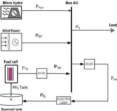
2. System Configuration
Block diagram of a hybrid Micro-hydro, Fuel-cell and Wind turbines system is depicted in Figure 1. The hybrid system consists of 3 types of power generator; Wind turbines unit, Micro-hydro and Fuel-cellunit connected to the load system through the inverter.The storage system consists of electrolyzer, hydrogen storage tank and fuel-cell required to store all excess power. Detailed component model and their specification, used in this study will be explained in the following sections.
Figure1.Configuration of proposed system
Figure 2. Daily load profile
3. Modeling of Renewable Energy Components 3.1. Wind Turbine Generator
The output power of each wind turbine unit is based on the rated capacity and the specification given by the manufacture. In this study, 100kW wind turbine is considered as a power generator. It has a rated capacity of 100 kW and provides alternating current (AC) at the output side.The output power from wind turbines can be described by equation (1).
0 5 10 15 20 25
4.5 5 5.5 6 6.5 7
7.5x 10
5
Time (hour)
L
o
a
d
d
e
m
a
n
d
(
W
Table1. Specification of wind turbine
Rated power (kW) 100
Cut-in (m/s) 3.5
Cut-out (m/s) 25
Rated (m/s) 12
Swept area of rotor(m2
) 314.16
Efficiency (%) 30
Figure 3. Wind speed data
Figure 4. Flow rate data
3.2. Micro-hydro Power
The electrical power generated by the hydro turbine can be determined using the following equation [5].
t calculated using the following equation [7].
) turbine. It can be calculated using the following equation [7].
whereQAvis the flow rate available to the hydro turbine (m3/s),Qminis the minimum flow rate of the
hydro turbine (m3/s),Qmaxis the maximum flow rate of the turbine (m3/s) [7]. Qmin is the minimum
flow rate, the minimum allowable flow rate through the hydroturbine; it is assumed that the hydro turbine can operated only if the available stream flow is equal to or exceeds this minimum value. It can be calculated using the following equation [7]:
D Qmaxis the maximum acceptable flow rate through the hydro turbine, expressed as a percentage
of the turbine’s design flow rate [7]. This simulation uses this input to calculate the maximum flow rate trough the hydro turbine, and hence the actual flow rate through the hydro turbine.
D
Basically, electrolyzer work based on the water electrolysis. A direct current is passed between two electrodes then submerged in water and decomposes into hydrogen and oxygen. Then, the amount of hydrogen can be collected from the anode side. Usually, the hydrogen produces by the electrolyzers at a pressure around 30 bars. Also, the reactant pressures within a Proton Exchange Membrane Fuel Cell (PEMFC) are around 1.2bar. For assumption, the electrolyzer is directly connected to the hydrogen tank. Transferred power from electrolyzer to hydrogen tank can be defined as follows [5]:
el Where
η
elis the efficiency of electrolyzer.3.4. Hydrogen Tank
The basic principle of energy stored in the hydrogen tanks is the same as in the battery banks. Everyhour energy stored in the hydrogen tanks can be described by using the following equation [5]: efficiency is 98%. Meanwhile, the mass of stored hydrogen, at any time step t, is calculated as follows [5]: Where, the Higher Heating Value (HHV) of hydrogen is equal to 39.7kWh/kg. The energy stored in the hydrogen tanks cannot exceed the constraint as follows [5]:
FC x FC k P inv FC
P − = tan −
η
(11) 3.6. Inverter
Inverter is an electrical device to convert electrical power from DC into AC form at the desired frequency of the load [5].
inv . INV P FC P L INV
P − =( + )
η
(12)
where
η
invis inverter efficiency.
4. Reliability and Objective Function
In this study, the objective function is the annual cost of system (ACS). Meanwhile, all economical components can be seen at Table 2. The ACS model is suitable to find the best benchmark of cost analysis. Annual cost of system convert the annual capital cost (ACC), annual operation maintenance (AOM), annual replacement cost (ARC) and annual customer damage cost (ADC). The components to be considered are windturbine, micro-hydro, electrolyzer, hydrogen tank, fuel-cell and inverter. ACS is calculated in the following equation [1]:
ADC ARC AOM ACC
ACS= + + +
(13)
Annual capital cost of each unit that does not need replacement during project lifetime is calculated as follows:
y) CRF(i cap C
ACS= ,
(14)
whereCcap is the capital cost of each component in US$, y is the project lifetime in year. CRF is
capital recovery factor, a ratio to calculate the present value of a series of equal annual cash flows. This factor is calculated as follows:
1 ) 1 (
) 1 (
− +
+ =
y i
y i i CRF
(15)
whereiis the annual real interest rate. The annual real interest rate includes the nominal interest and annual inflation rates. This rate is calculated as follows:
) 1 (
) ' (
f f i i
+ − =
(16)
wherei’ is the loan interest and f is the annual inflation rate. The annual operation and maintenance cost of the system (AOM) as a function of capital cost, reliability of components λ
and their lifetime can be determined using the following equation:
y cap
C
AOM = (1−
λ
)/(17)
) , (i yrep SFF rep C ARC=
(18)
whereCrep is the replacement cost of fuel cell and electrolyzer in US$, yrep is the lifetime of
electrolyzer and fuel cell in year. In this case the replacement cost of battery banks is similar to its capital cost. SFF is the sinking fund factor, a ratio to calculate the future value of a series of equal annual cash flows. This factor is calculated as follows:
1 ) 1
( + −
=
y i
i SFF
(19)
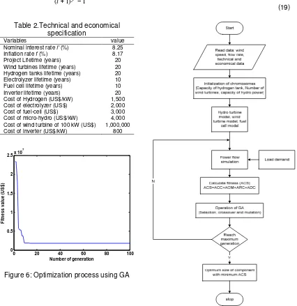
Table 2.Technical and economical specification
Variables value
Nominal interest rate i' (%) 8.25
Inflation rate f (%) 8.17
Project Lifetime (years) 20
Wind turbines lifetime (years) 20 Hydrogen tanks lifetime (years) 20 Electrolyzer lifetime (years) 10
Fuel cell lifetime (years) 10
Inverter lifetime (years) 20
Cost of Hydrogen (US$/kW) 1,500
Cost of electrolyzer (US$) 2,000
Cost of fuel-cell (US$) 3,000
Cost of micro-hydro (US$/kW) 4,000 Cost of wind turbine of 100 kW (US$) 1,000,000
Cost of inverter (US$/kW) 800
Figure 5.Optimization process using Genetic Algorithm
Figure 6: Optimization process using GA
5. Optimization Procedure using Genetic Algorithm
Simulation method utilizes genetic algorithm (GA) to determine the optimal sizing of the hybrid system. The concept of GA is different from traditional search and optimization method used to solve the engineering problems. The basic idea of GA is taken from genetic process in
0 20 40 60 80 100
0 0.5 1 1.5 2
2.5x 10
7
Number of generation
F
it
n
e
s
s
v
a
lu
e
(
U
S
$
biology that used artificially to optimal solution based on na find the optimum size of hydro To process this stud demand are initially set as th micro-hydro are randomly c consists of three genes in form NWT is the number of wind tu population, the annual powe power supply are repeated for in the beginning of the sim preserved and compared with best chromosome in the final hybrid system. In order to sele processing the next generati selection process. In this sim 0.75 and 0.015, respectively
The convergence curve be seen that the optimal value can be considered as a fair ter
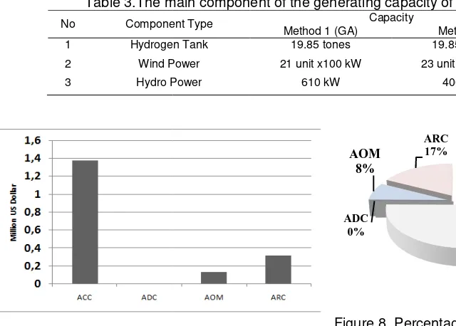
6. Results and Analysis Table 3 depicts the (method 1) and trial and erro Leuwijawa hybrid power syste optimum system using Geneti
Table 3.The m
No Compone
1 Hydrogen
2 Wind P
3 Hydro P
Figure 7.Cost element of pro
The optimum capacity turbine generator units each1 to design such system is US$ of US$ 0.14 million and ARC results can be seen in the Fi
to build search algorithms. This technique is intro natural selection. The main objective of the propo rogen tanks, number of wind turbines and number udy, the annual data of flow rate of river, wind the inputs. Then, the size of hydrogen tanks, w chosen to become the GA chromosomes. Ea rm of [NHyT, NWT, NHyd]; where NHyT is the number o turbines and NHyd is number of micro-hydro. After wer supply simulations are performed. The simu for each chromosome until it reaches the final gene imulation process. Each generation of the best
ith the best chromosome obtained from the next al generation is considered as the optimum param elect the chromosomes subjected to the crossover ation population, the roulette wheel method is co
imulation, the crossover and mutation probability
ves of the GA for the system under study is shown lues can be obtained closed to 70 generations. Hen termination criterion.
he capacity of each component that was optim rror (method 2). The optimum system size will be
stem, located in Central Java, Indonesia. The co etic Algorithm is presented in Figure 7.
main component of the generating capacity of hybr
nent Type Capacity
Method 1 (GA) Method 2
en Tank 19.85 tones 19.85 tone
Power 21 unit x100 kW 23 unit x100
Power 610 kW 400 kW
proposed configuration Figure 8. Percentages ocost
city of the components are, hydrogen tank of 19.8 h100k Wand micro-hydro power of 610kW. In this $1.83 million. This cost composed of ACC ofUS$ 1 RC isUS$0.3 million and requires no annual cos
troduced to find the posed method is to er of micro-hydro. nd speed and load , wind turbines and Each chromosome r of hydrogen tanks, ter setting the initial ulations of annual neration as defined st chromosome is ext generation. The ameter value of the er and mutation for considered as the ity are assumed as
n in Figure 6. It can ence, 100 iterations
ptimized using GA is case overall cost $ 1.35 million, AOM ost for ADC.These of the cost of each
part of the cost is; annual capital cost=75%, annual peration and maintenance= 8 %, annual replacement cost=17% and annual customer damage cost=0% interruption the value is zero. It means that the proposed configuration has 100% reliability.
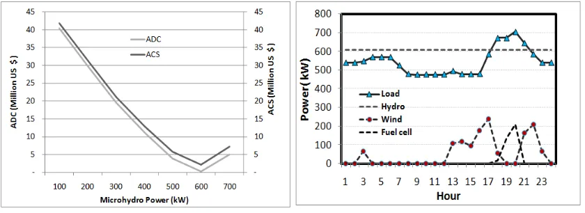
Figure 9. Optimization for Micro-hydro PowerVs ADC and ACS
Figure 10. Operation of each power system in 24 hour
Figure 9 illustrates the optimum condition provided by genetic algorithm that the Micro-hydro size is 610 kW. Other components are 21 units of wind turbine with each capacity is 100 kW,the annual cost of systemis US$ 2.08 million.In this condition, the cost for annual customer damage is zero. However, the annual capital cost of method 2 was found as US$ 12.83 million
Figure 10 demonstrates the daily profile of optimum component sizes to meet the load. The hydro supplies constantly at 610 kW for 24 hour. When the load is lower the micro-hydro power, the remaining energy is for producing micro-hydrogen whilethe fuel-cell does not supply any power to the load. Then, during the peak load, the fuel-cell contributes power to the load, sharing with the micro-hydro.
7. Conclusion
Intelligence method by mean of genetic algorithm has been successfully tested to find the optimal size of hydrogen, wind turbines and micro-hydro system for remote island application. The simulation resultsachieving an optimum configuration consist of 19.85 Tons of hydrogen tanks, 610kW of micro-hydro unit and 21 units of wind turbine with each capacity is 100kW. The annual cost of system isUS$ 2.08 million, while the annual capital cost is US$ 1.35 million.This system is planned to be used for electrification in the Leuwijawa village Central Java, Indonesia.
References
[1] H Suryoatmojo, AA Elbaset, T Hiyama. Economic and Reliability Evaluation of Wind-Diesel-Battery System for Isolated Island Considering CO2 Emission. IEEJ Trans. PE. 2009; 129 (8): 1000-1008.
[2] Doaa M Atia, Faten H Fahmy, Ninet M Ahmed, Hassen T Dorrah. Modeling and Control PV-Wind Hybrid System Based On Fuzzy Logic Control Technique.TELKOMNIKA. 2012; 10(3): 431-441. [3] H Suryoatmojo, T Hiyama, AA. Elbaset, M Ashari. Optimal Design of Wind-PV-Diesel-Battery
System using Genetic Algorithm. IEEJ Trans.PE.2009; 129(3): 413-420.
[4] Mithun M Bhaskar, Sydulu Maheswarapu. A Hybrid Genetic Algorithm Approach for Optimal Power Flow. TELKOMNIKA. 2011; 9(2): 211-216.
[5] A Kashefi Kaviani, GH Riahy, SHM Kouhsari. Optimal Design of A Reliable Hydrogen-Based Stand-Alone Wind/PV Generating System Considering Component Outages. Renewable Energy. 2009; 34: 2380-2390.
[6] R Dufo Lopez, JL Bernal-Agustin. Design and Control Strategies of PV-Diesel Systems using Genetic Algorithms. Solar energy. 2005; 79: 33-46.