UNIVERSITI TEKNIKAL MALAYSIA MELAKA
DEVELOPMENT OF THIN FLAT CHASSIS OF
MULTIPURPOSE REMOTE CONTROLLED POWERED
PLATFORM
This report submitted in accordance with requirement of the Universiti Teknikal Malaysia Melaka (UTeM) for the Bachelor’s Degree in Mechanical Engineering
Technology (Automotive Technology) with Honours.
by
AHMAD DANIAL BIN ZAKARIA B071210506
900422-03-5427
i
TAJUK: Development of thin flat chassis of multipurpose remote controlled powered platform.
SESI PENGAJIAN: 2015/16 Semester 1.
Saya AHMAD DANIAL BIN ZAKARIA
mengaku membenarkan Laporan PSM ini disimpan di Perpustakaan Universiti Teknikal Malaysia Melaka (UTeM) dengan syarat-syarat kegunaan seperti berikut:
1. Laporan PSM adalah hak milik Universiti Teknikal Malaysia Melaka dan penulis. 2. Perpustakaan Universiti Teknikal Malaysia Melaka dibenarkan membuat salinan
untuk tujuan pengajian sahaja dengan izin penulis.
3. Perpustakaan dibenarkan membuat salinan laporan PSM ini sebagai bahan pertukaran antara institusi pengajian tinggi.
4. **Sila tandakan ( )
BORANG PENGESAHAN STATUS LAPORAN PROJEK SARJANA MUDA
(Mengandungi maklumat yang berdarjah keselamatan atau kepentingan Malaysia sebagaimana yang termaktub dalam AKTA RAHSIA RASMI 1972).
(Mengandungi maklumat TERHAD yang telah ditentukan oleh organisasi/badan di mana penyelidikan dijalankan)
** Jika Laporan PSM ini SULIT atau TERHAD, sila lampirkan surat daripada pihak berkuasa/organisasi
berkenaan dengan menyatakan sekali sebab dan tempoh laporan PSM ini perlu dikelaskan sebagai
SULIT atau TERHAD.
TIDAK TTERHAD TERHAD
ii
DECLARATION
I hereby, declared this report entitled “Development of Thin Flat Chassis of Multipurpose Remote Controlled Powered Platform” is the results of my own
research except as cited in references.
Signature : ……….
Author’s Name : AHMAD DANIAL BIN ZAKARIA
iii
APPROVAL
This report is submitted to the Faculty of Engineering Technology of UTeM as a partial fulfillment of the requirements for the degree of Bachelor’s Degree in Mechanical Engineering Technology (Automotive Technology) with Honours.The member of the supervisory is as follow:
iv
ABSTRAK
Laporan ini memperkenalkan kerangka nipis dan rata untuk kenderaan kawalan
jauh. Kerangka ini akan diaplikasikan pada kenderaan Formula Varsity (FV).
Rekabentuk kerangka keluli dilaksanakan menggunakan perisian CAD iaitu CATIA
V5R20. Dua kes agihan beban ke atas galang, kerosakan dan daya telah dianalisa.
Kesemua tiga paksi; paksi-x, paksi-y, dan paksi-z terlibat dalam analisis-analisis itu.
Keputusan dari analisis-analisis tersebut termasuklah tekanan Von Mises, sesaran,
dan tekanan utama tensor. Selain itu, analisis-analisis yang dilakukan adalah untuk
mengkaji kesesuaian kerangka tersebut dengan konsep kereta lumba. Dari
analisa-analisa yang telah dijalankan, kajian menunjukkan tekanan Von Mises maksima
ialah 6.79 x 10⁶ N/m² dan pemesongan maksima ialah 0.00356mm untuk
pemesongan pulasan longitude. Kerangka tersebut mengalami tekanan ketegangan
pada paksi x, y, dan z dengan nilai 1.07 x 10⁶ N/m², 5.82 x 10⁶ N/m², and 7.48 x 10⁵
N/m² masing-masing. Kajian selanjutnya dengan membina prototaip sebenar dan menjalankan uji kaji terhadap rolling, yawing dan pitching untuk kestabilan
v
ABSTRACT
vi
DEDICATION
To my beloved wife Adibah binti Razali, my son Ahmad Adwa, my kind parents Zakaria bin Seman and Anita binti Ahmad,
my mother in law Ruslah Binti Omar, and my supportive family members.
vii
ACKNOWLEDGEMENT
I would like to express my utmost appreciation to Mr. Muhammad Zaidan bin Abdul Manaf who is my final year project supervisor. The supervision and support that he gave truly help the progression and smoothness of completing this project. The co-operation is much indeed appreciated.
My grateful thanks also go to all lecturers who always give advices and motivate me to work harder and smarter. I believe that success is not a dime a dozen.
I am also heartily thankful my wife for her endless support and encouragement. She made me agree that verily with every hardship, there is relief.
viii
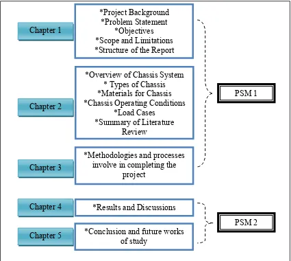
1.4 Scope and Limitations 3
1.5 Structure of the Report 4
CHAPTER 2 5
2.1 Introduction 5
2.2 Chassis System 5
2.2.1 Definition of Chassis 5
2.2.2 Chassis Structures 6
2.2.3 Functions of Chassis 6
2.3 Chassis Design 6
2.3.1 Types of Chassis 7
2.3.2 Comparison Between Different Types of Chassis 11
2.3.3 Requirements of the Chassis Design 13
2.4 Materials for Chassis 13
2.4.1 Types of Materials for the Chassis 13
2.4.2 Materials Selection 16
ix
2.6.3 Combined Bending and Torsion 26
2.6.4 Lateral Loading 26
CHAPTER 3 28
3.0 Introduction 28
3.1 Project Steps 28
3.2 Phase 1: Identifying Customer Needs 30
3.2.1 Define the Vehicle Purpose 30
3.2.2 Define the Size and Configurations 31
3.2.3 Define the Load for Components and System 33
3.3 Design Base Structure 36
3.4 Phase 2: Topology (remove material) 37
3.4.1 Using topology method to remove, unnecessary material. (Objective:
light weight). 37
3.5 Phase 3: Analysis structure (base run) 39
3.5.1 Realization concept using CAD software. 39
3.5.2 Analysis model 41
CHAPTER 4 49
4.1 Introduction 49
4.2 Analysis for Deformation 49
4.2.1 Vertical Bending Deformation 50
4.2.2 Logitudinal Torsion Deformation 53
4.2.3 Lateral Bending Deformation 56
4.3 Analysis for Force 59
4.3.1 Vertical Force 59
4.3.2 Longitudinal Force 61
4.3.3 Lateral Force 63
x
CHAPTER 5 67
5.1 Conclusion 67
5.2 Significance of the Study 67
5.3 Recommendations 68
REFERENCES 69
APPENDIX 71
A: Gantt Chart 71
B: Executive Summary 72
xi
LIST OF TABLES
TABLE TITLE PAGE
2.1 Advantages, disadvantages and application of chassis 11
2.2 Elements involved in translation step 17
3.1 Criteria and specification 32
3.2 Information for the short item 34
3.3 Component and mass 35
3.4 Information for the short item 37
4.1 Description of analysis results 49
xii
2.5 Lotus Elan backbone chassis. 10
2.6 Example of space frame chassis structure for race car 11
2.7 Steps for materials selection 17
2.8 Automobile life cycle 20
2.9 Vertical bending deformation mode 21
2.10 Longitudinal torsion deformation mode 22
2.11 Lateral bending deformation mode 23
2.12 Horizontal lozenging deformation mode 23
2.13 Bending load case 25
2.14 Torsion load case 26
2.15 Combined bending and torsion load case 26
2.16 Lateral loading case 27
3.6 Direction of dynamic loads 35
3.7 Design base structure 37
3.8 Topology method to remove unnecessary material 38
xiii
FIGURE TITLE PAGE
3.10 Manikin concept using CATIA software 41
3.11 Arrow for the analysis tests 42
3.12 Material Properties Data 42
3.13 Vertical Bending Deformation (load applied at equally in driver cabin)
43
3.14 Longitudinal Torsion Deformation (load applied at equally in driver cabin)
44
3.15 Lateral Bending Deformation (load applied at equally in driver cabin)
45
3.16 Longitudinal force (load applied at bulk head front suspension) 46 3.17 Vertical force (load applied at lower front suspension) 47 3.18 Lateral force (load applied at right side front suspension) 48
4.1 Translational Displacement of Vertical Bending Deformation 50 4.2 Von-Mises stress distribution for a side members center force 51 4.3 Maximum Principal Stress Vertical Bending Deformation 52 4.4 Displacement Longitudinal Torsion Deformation 53
4.5 Von Mises stresses during Torsional Test 54
4.6 Maximum Principal Stress Longitudinal Torsion Deformation 55
4.7 Displacement Lateral Bending Deformation 56
4.8 Von Misses stresses during Side Impact Test 57 4.9 Maximum Principal Stress Lateral Bending Deformation 58 4.10 Von Mises stress during vertical force analysis (load applied at
lower front suspension)
59
4.11 Maximum Principal Stress Vertical Force 60
4.12 Von Mises stress during longitudinal force (load applied at bulk head front suspension)
61
4.13 Maximum Principal Stress Longitudinal Force 62
4.14 Von Mises stress during lateral force 64
xiv
LIST OF ABBREVIATIONS
2D - Two Dimession 2WD - Two Wheel Drive CAD - Computer-Aided Design CAE - Computer-Aided Engineering CG - Center Gravity
1 structural system that supports other components of a physical construction. Design is one of the main processes in producing the new vehicle. This will help to make a new vehicle that follows the criteria needed by the designer and the customer. Design, usually considered in the context of applied arts, engineering, architecture, and other creative endeavors, is used both as a noun and a verb. As a verb, to design refers to the process of originating and developing a plan for a product, structure, system, or component. As a noun, a design is used for either the final solution plan, for example proposal, drawing, model, description or the result of implementing that plan, for example object produced, result of the process. More recently, processes in general have also been treated as products of design, giving new meaning to the term process design. There are three main sections in the frame such as body-on-frame, chassis and sub frame. All of these sections are important to support the entire body of the new Vehicle. The design and the analysis of these three sections will be done based on the criteria of the new vehicle.
2
parts and components together. Having a well-designed chassis is important to ensure the safety, performance and any the place.
1.2 Problem Statement
This study is conducted to seek a solution regarding car chassis which powered by electric motor system. The limitation for that particular chassis design is it uses more space to locate electric motor, battery, and other components related to electric system. Therefore, development of thin flat chassis will enable all components in the electric system utilize the chassis space. Other than that, electrical components such as electric motor, battery, and other components can be located in their specific yet the most suitable area.
The current available chassis is heavy when all components are joined together is the other problem which drives to realization of this study. In fact, mass is the most important point to be considered in determining the vehicle’s performance. Therefore, this project is done to design and develop lighter chassis which provides equivalent strength with the heavier one when dealing with specified amount of loads.
1.3 Objectives
The main goal of this project is to develop the chassis system for multipurpose remote controlled powered platform. In order to achieve this aim, this study is conducted based on these specific objectives:
i. To design the thin flat ladder chassis concept.
ii. To reduce the weight of chassis using topology optimization method.
3
1.4 Scope and Limitations
The project scope of the chassis system for the thin flat chassis of multipurpose remote controlled powered platform are limited to the several process and equipment that have been provided. Hence, a few scope have been drawn and they are;
a) To study about the design of the chassis of current vehicle. b) Conceptual design.
c) Develop designs for the thin flat ladder chassis of multipurpose remote controlled powered platform.
d) Analyze the performance using CAE of the new designs that follow the requirements of the new vehicle.
4
1.5 Structure of the Report
5
CHAPTER 2
LITERATURE REVIEW
2.1 Introduction
This chapter will be focused on the research information and the outcome of the study. This information then will be used as the guideline to find the most suitable material and design based on the factor and the supported theory to finalize the design of the development of thin flat chassis of multipurpose remote controlled powered platform.
2.2 Chassis System
This section discusses on several issues related to the chassis system such as its definition, functions, requirements of its design, and also types of the chassis. These basic information will provide an overview for the project.
2.2.1 Definition of Chassis
Chassis is a French term which provides two distinct definitions according to vehicle category (H. Crouse & Rajput, 2008):
i. Heavy vehicle - the overall shape of the vehicle except the body.
ii. Light vehicle of mono construction – the entire body except additional fittings in the body.
6
and stability to the vehicle under various conditions. The rigidity, stiffness, and bending of the vehicle is thus highly depending on the chassis (Linton, 2002).
2.2.2 Chassis Structures
Chassis structures are categorized into 3 prime categories (Demir, 2012): i. Frame – separated from the body
ii. Underbody – unitized body iii. Sub-frame – auxiliary structure
2.2.3 Functions of Chassis
Generally, functions that are expected to be fulfilled by an automobile chassis are as follows (Linton, 2002):
i. provide mounting points for the mechanical parts ii. carry the maximum load safely
iii. provide rigidity for accurate handling
iv. protect the occupants against external impact v. hold all components together while driving vi. endure shock loading
vii. accommodate twisting on even road surface
2.3 Chassis Design
7 2.3.1 Types of Chassis
Different types of the chassis are including: i. Ladder
ii. Twin tube iii. Four tube iv. Monocoque
v. Backbone vi. Spaceframe
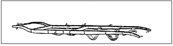
2.3.1.1 Ladder
As the name implies, it is a ladder-like shape with two longitudinal rails as depicted by Figure 2.1 below. Several lateral and cross braces are connected to those rails. In this chassis design, large diameter tubes are used. Weight of the vehicle uses ladder chassis is sustained by the axles. The ladder chassis is one of the oldest forms of the automobile chassis which used in car construction until 1950’s. It was also applied for racing until the mid of 1930’s (Linton, 2002). Ability to resist the bending is taking into account for its design. However, torsional stiffness is not considered for this type of chassis (Linton, 2002). In the 1930s, additional cruciform bracing was helpful in increasing the torsional stiffness to the chassis. It is still be used in some Sports Utility Vehicles (SUV) available in today’s market.
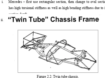
8 2.3.1.2 Twin Tube
In the mid 1930’s, the ladder frame chassis was modified to enhance its operation’s efficiency by improving torsional stiffness. It is known as ‘twin tube’ chassis which shown by Figure 2.2. Design of side rails of the ladder chassis is made deeper and boxed. Through the improved design, torsional stiffness is approximated to be thousand times greater than an open section as before. Disadvantage of twin tube chassis is low efficiency due to the weight of the large tubes. Some examples of twin tube chassis are:
i. Mercedes – first use rectangular section, then change to oval section which has high torsional stiffness as well as high bending stiffness due to increased section depth.
ii. Auto Union – use tubular section.
Figure 2.2: Twin tube chassis.
2.3.1.3 Four Tube
9
Figure 2.3: Four tube chassis
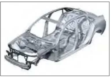
2.3.1.4 Monocoque
Monocoque chassis is best to be described as a single piece structure which defines the final shape of an automobile. Example of monoque chassis is illustrated in Figure 2.4. Steel plated monocoque chassis are used for 99% of vehicles produced today due to the low cost and suitability for robotized production offered (Chandra, Sreenivasulu, & Hussain, 2012).
Figure 2.4: Monocoque chassis.
It is manufactured through sequence of processes as follows: i. Pressing of metal sheets using big stamping machines.