PEMBANGUNAN SISTEM PENDORONGAN KENDERAAN HIBRID DUA ALAM
UNTUK OPERASI PENYELAMATAN MARIN
(DEVELOPMENT OF HYBRID AMPHIBIOUS VEHICLE PROPULSION SYSTEM
FOR MARINE SAFETY AND RESCUE OPERATION)
MUHAMMAD ZAIDAN ABDUL MANAF
RESEARCH VOTE NO:
PJP/2012/FKM(17C)/S01109
JABATAN TEKNOLOGI KEJURUTERAAN MEKANIKAL
FAKULTI TEKNOLOGI KEJURUTERAAN
UNIVERSITI TEKNIKAL MALAYSIA MELAKA
i
ACKNOWLEDGEMENT
First of all, I express my gratitude to Allah Almighty on the completion of this project. A great appreciation to research members especially to final year student under supervision of Dr Muhammad Zahir Hassan who developed the prototype of hybrid propulsion system. Finally, thanks to Universiti Teknikal Malaysia Melaka for financial support under Short Term Grant vote no: PJP/2012/FKM(17C)/S01109.
ii
PEMBANGUNAN SISTEM PENDORONGAN KENDERAAN HIBRID DUA ALAM UNTUK OPERASI PENYELAMATAN MARIN
(Kata kunci: Sistem dorongan hybrid elektrik, kenderaan dua alam)
Dalam laporan ini, pembangunan sistem penggerak hibrid elektrik bagi penggunaan kenderaan dua alam dibentangkan. Kenderaan hibrid dua alam – Amphibious Hybrid Vehicle (AHV) dibangunkan sebagai pengangkutan yang boleh beroperasi di atas tanah dan air yang berguna untuk pasukan penyelamat dalam operasi menyelamat. AHV digerakkan oleh motor elektrik di atas tanah, manakala di atas air, AHV dikemudikan oleh enjin pembakaran dalaman – Internal Combustion Engine (ICE) dan ICE juga berperanan untuk menjanakan tenaga elektrik. Definasi kenderaan hibrid elektrik (HEV) adalah menggunakan sumber kuasa daripada gabungan antara motor elektrik dan enjin pembakaran dalaman. Masalah pada kenderaan elektrik (EV) yang menggunakan motor elektrik semata-mata sebagai sumber kuasa penggerak mempunyai kelemahan pada sistem penyimpanan tenaga. Laporan ini bertujuan untuk membangunkan satu sistem penggerak hibrid elektrik yang optimum yang mempunyai kebolehpercayaan yang tinggi, minimum dalam penggunaan bahan api, dan mudah untuk dibangunkan. Kaedah kajian yang digunakan adalah; reka bentuk, pembangunan dan analisa kenderaan. Faktor utama yang perlu dipertimbangkan dalam usaha untuk membangunkan sistem penggerak elektrik hibrid adalah kuasa yang diperlukan oleh bateri untuk menghantar kepada motor elektrik bagi menggerakkan kenderaan. Setelah reka bentuk gabungan antara ICE dan motor elektrik selesai, maka analisis eksperimen akan dijalankan untuk menentukan kebolehpercayaan dan ketahanan. Keputusan analisis Matlab Simulink berdasarkan model matematik dijalankan untuk menentukan kuasa yang diperlukan sebelum proses fabrikasi pembangunan berlaku.
Penyelidik:
Muhammad Zaidan Bin Abdul Manaf (Ketua)
Dr Muhammad Zahir Bin Hassan, Mohd Hafidzal Bin Mohd Hanafi, Mohd Noor Asril Bin Saadun, Khairul Azha Bin A Aziz, Faiz Bin Arith
iii
DEVELOPMENT OF HYBRID AMPHIBIOUS VEHICLE PROPULSION SYSTEM FOR MARINE SAFETY AND RESCUE OPERATION
(Keywords: Hybrid electric propulsion system, amphibious hybrid vehicle.)
In this report, the development of hybrid electric propulsion systems for amphibious vehicle is presented. Amphibious Hybrid Vehicle (AHV) was developed as a transportation that can operate on land and water which is useful for rescue teams in rescuing operations. AHV is driven by an electric motor on the land, while on the water, AHV is propelled by an Internal Combustion Engine (ICE) and ICE also acts to generate the electrical energy. Definition of hybrid electric vehicle (HEV) is a combination of resources from the electric motor and the internal combustion engine. Problems in the electric vehicle (EV) using the electric motor alone as the driving power source has a weakness in the energy storage system. This report aims to develop a hybrid electric propulsion systems that are optimized with high reliability, minimum fuel consumption, and easy to develop. The methodology used in this study is; the design, development and analysis of the vehicle. The main factor to be considered in order to develop a hybrid electric propulsion system is power required by the battery to deliver to the electric motor to drive the vehicle. After the design of combination ICE and electric motor completed the analysis of experiments will be conducted to determine the reliability and durability. The results of analysis Matlab Simulink based on mathematical model is conducted to determine the required power before the fabrication process development take place.
Key-researchers:
Muhammad Zaidan Bin Abdul Manaf (Principal)
Dr Muhammad Zahir Bin Hassan, Mohd Hafidzal Bin Mohd Hanafi, Mohd Noor Asril Bin Saadun, Khairul Azha Bin A Aziz, Faiz Bin Arith
iv
TABLE OF CONTENTS
ACKNOWLEDGEMENT ... i
PEMBANGUNAN SISTEM PENDORONGAN KENDERAAN HIBRID DUA ALAM UNTUK OPERASI PENYELAMATAN MARIN ... ii
DEVELOPMENT OF HYBRID AMPHIBIOUS VEHICLE PROPULSION SYSTEM FOR MARINE SAFETY AND RESCUE OPERATION ... iii
TABLE OF CONTENTS ... iv
LIST OF FIGURES ... vi
LIST OF TABLES ... vii
LIST OF SYMBOLS AND ABBREVIATIONS ... viii
LIST OF APPENDICES ... x
CHAPTER 1 ... 1
PROJECT BACKGROUND ... 1
PROJECT OBJECTIVES ... 2
PROJECT SCOPES ... 3
CHAPTER II ... 4
MODEL DEVELOPMENT ... 4
DEVELOPMENT PROCESS ... 4
Design process ... 4
DeterminingHybrid Configuration ... 5
Determiningthe tractive force ... 6
Determining power ... 8
CHAPTER III ... 9
ANALYSIS RESULTS ... 9
POWER ANALYSIS ... 9
v
FABRICATION PROCESS ... 12
FABRICATION OF THE HYBRID ELECTRIC PROPULSION SYSTEM ... 12
CHAPTER V ... 13
CONCLUSIONS... 13
CONCLUSIONS ... 13
RECCOMENDATIONS ... 13
REFERENCES ... 14
APPENDICES ... 18
APPENDIX A: HYBRID’S COMPONENTS ... 18
APPENDIX B: VEHICLE CONFIGURATIONS ... 22
APPENDIX C: HYBRIDS’S SYSTEM ELECTRICAL CIRCUIT ... 25
vi
LIST OF FIGURES
Figure 1 Planning of the power flow in a AHV. ... 5
Figure 2 Mathematical model of vehicle. ... 7
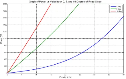
Figure 3 Graph of Power vs. Velocity on 0, 5, and 10 Degree of Road Slope. ... 10
Figure 4 Internal combustion engine. ... 18
Figure 5 Electric motor controller. ... 19
Figure 6 Battery pack. ... 19
Figure 7 Electric motor. ... 20
Figure 8 Power inverter. ... 20
Figure 9 Rectifier. ... 21
Figure 10 Charger. ... 21
Figure 11 Vehicle’s front view. ... 22
Figure 12 UTeM’s Amphibious Hybrid Vehicle. ... 22
Figure 13 Vehicle’s top view. ... 23
Figure 14 Indiacator, switch and connecter. ... 23
Figure 15 Electrical hybrid propulsion system. ... 24
Figure 16 Hybrid system electrical circuit. ... 25
vii
LIST OF TABLES
viii
LIST OF SYMBOLS AND ABBREVIATIONS
Overall efficiency Gearbox efficiency Driveshaft efficiency Wheel efficiency Power
Power experienced by wheel
Required mechanical power
Real power needed from battery to electric motor
Aerodynamic drag
Rolling resistance force
Gradient force
Acceleration force
Total traction force
Air density
Drag coeffiecint
Vehicle frontal area
Velocity
Rolling resistance coefficients
Mass
ix
Gravity acceleration
Angle
Acceleration
Wheel raduis
ICE Internal Combustion Engine
EV Electric Vehicle
HEV Hybrid Electric Vehicle
AHV Amphibious Hybrid Vehicle
DC Direct Current
AC Alternating Current
CO2 Carbon Dioxide
DOF Degree-of-Freedom
PM Permanent Magnet
BLDC Brushless Direct Current (Motor) VRLA Valve-Regulated Lead-Acid NiMH Nickel-Metal Hydride Li-Ion Lithium-Ion
NiCd Nickel-Cadmium
x
LIST OF APPENDICES
APPENDIX A: HYBRID’S COMPONENTS ... 18
APPENDIX B: VEHICLE CONFIGURATIONS ... 22
APPENDIX C: HYBRIDS’S SYSTEM ELECTRICAL CIRCUIT ... 25
1
CHAPTER 1
INTRODUCTION
PROJECT BACKGROUND
Hybrid vehicle means combination of two or more power source to increase the overall efficiency (Ogawa et al, 2003). The types of hybrid can be classified based on driveline configuration. There are three common types of hybrid design configuration which are series, parallel, and series-parallel.
Although further improvements on vehicle fuel economy since the last 40 years has been done, the average efficiency in the use of gasoline ICE normal operation is only at 15%. While other 85% is lost to the environment as engine heat, exhaust gas heat, aerodynamic drag, rolling resistance of the tires, losses at the driveline and during braking (Germen, 2003). Addition of an electric motor and electric energy storage from ICE can increase diversity of efficiency significantly, depends on the system design.
Common features of most hybrids that improve fuel economy are: (i) Idle stop
2
(Germen, 2003). While during others time, fuel can be saved by turning off the engine when the vehicle is under deceleration, thus CO2 emissions is not released. The idle stop is possible because restarting the engine happen at very low engine speed. The mix of air-fuel is combust at crank speed of 400 rpm. (Ogawa et al, 2003)
(ii) Regenerative braking
During deceleration or braking driving phase, the system will absorb the braking energy and store it in an energy storage device such battery or other components for future use, and it is also helps in charging the battery (Halderman, 2009).
(iii) Power-assist
The electric motor gives additional power to the ICE when the vehicle is accelerated. Assistance from the power-assist module can reduce the size of the engine and improve the fuel efficiency without reducing the overall performance of the vehicle. Application of power-assist in Toyota Prius shows that the performance of 1.8cc ICE is comparable to 2.4cc performance with power-assist (Toyota, 2012).
(iv) Engine efficiency
The ICE efficiency is low during low speed and low load operation. Therefore, to increase system efficiency during this condition, the electric motor can be used as alternative power supply. Hence, fuel consumption and emission is zero at this time.
PROJECT OBJECTIVES
The objectives of the project are:
1. To design the electric hybrid propulsion system for amphibious vehicle.
3
3. To provide tehnical information for amphibious electric hybrid propulsion system.
PROJECT SCOPES
The scopes of the project are as follows: 1. For objectives #1
- Benchmark the current electric hybrid systems use in vehicle.
- Select the suitable propulsion system concept for land and water operation. 2. For objective #2
- Run multiple hybrid components configuration to get minimum power loss value. - Test suitable parameter setting to get maximum power from hybrid system. 3. For objective #3
4
CHAPTER II
MODEL DEVELOPMENT
DEVELOPMENT PROCESS
In development of the hybrid electric propulsion system, the following considerations need to be adhered:
i. Design of hybrid configuration. ii. Power requirement.
iii. Component selection and arrangement. iv. Vehicle size.
The first two criteria are very important parameters in order to design a hybrid electric propulsion system. Apart from that, we also have to make assumption of the following:
i. Vehicle moving in constant velocity without acceleration. ii. There is no energy loss from ICE.
Design process
5
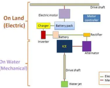
Figure 1 Planning of the power flow in a AHV.
Determining Hybrid Configuration
The AHV hybrid system in Figure 1 consists of seven main components as correlation in the hybrid system of vehicle. When the ICE is running, the alternator that be linked to the crankshaft of ICE will generate the electricity according to the rotation of the crankshaft. The increase speed of crankshaft rotation will increase the production of Alternating Current (AC). Then, the regulator will regulate the unstable rectified AC to the steady at 12Volt of direct current (DC). The 12Volt DC from regulator is recharged the 12 Volt batteries which is used as a power bank. Next, the inverter will amplify the 12Volt DC to the 240Volt DC. The amplified current is then use to run the charger. Charger is use to charge the 60Volt DC battery pack that is required by the electric motor to operate. AHV also come with plug-in charging system to charge power bank as an alternative to ICE charging system.
6
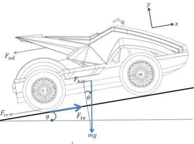
The factors that determine the amount of the power from batteries which can transmit to motor electric are: tractive force. It is a summation of aerodynamic resistance force, rolling resistance force, hill climbing force, and acceleration force (Rozaini, 2011). As shown in Figure 2, the vehicle with mass, m moving at velocity, von the slope with an angle, θ should overcome all the opposing force.
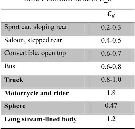
Table 1 Common value of C_d.
Sport car, sloping rear 0.2-0.3 Saloon, stepped rear 0.4-0.5 Convertible, open top 0.6-0.7
Bus 0.6-0.8
Truck 0.8-1.0
Motorcycle and rider 1.8
Sphere 0.47
Long stream-lined body 1.2
Determining the tractive force
7
Figure 2 Mathematical model of vehicle.
The following equations are derived to develop the mathematic model for power calculations.
The aerodynamics resistance force:
(1)
The rolling resistance force:
(2)
Hill climbing force:
(3)
Inertial force:
(4)
Total tractive force:
(5)
Power required by batteries for motor electric:
8
Determining power
9
CHAPTER III
ANALYSIS RESULTS
POWER ANALYSIS
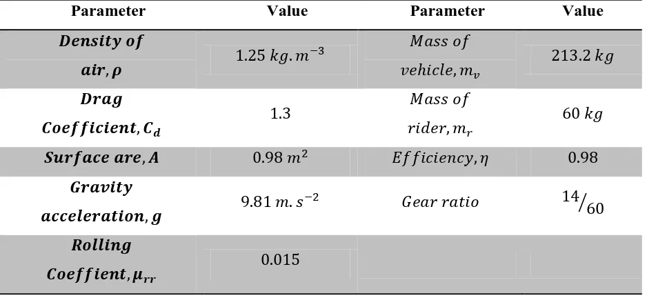
The analysis is focus only on electric motor and the result of analysis is determined by equations (1) to (6). The equation parameter is shown in Table 2. From Figure 2, the frontal area of vehicle is calculated as stated in Table 2. From Table 1, there is no common value of drag coefficient for this type of vehicle, so the value is assumed as in Table 2. Total of mass
is where the mass of rider is to be assumed with typical weight around . The
vehicle is assumed moving on incline road surface gradient of , and degrees. Table 2 Assumption and parameter.
Parameter Value Parameter Value
⁄
10
With all parameters and assumptions, the result for analysis on power required for vehicle is shown on the graph in Figure 3. The analysis is conducted by using Matlab Simulink Analysis and the block diagram is shown in appendix.
Figure 3 show that the required power of the vehicle to move at any constant velocity is absolutely differences. Power required by battery is proportional with the vehicle speed. Therefore, the speed of the vehicle is depends on the capacity of the power bank. According to the graph, when the vehicle is move on a flat road at speed of , the battery need to supply the power of to the electric motor. By using the same battery power, if the vehicle move along the slope of , the vehicle can speed up to . The speed of vehicle is up to when vehicle move along of slope.
11
12
CHAPTER IV
FABRICATION PROCESS
FABRICATION OF THE HYBRID ELECTRIC PROPULSION SYSTEM
13
CHAPTER V
CONCLUSIONS
CONCLUSIONS
In this paper, the development process of the hybrid electric propulsion system is properly demonstrated. It started with proper power planning, then the components integration and finally system testing and analysis. Maximum 3kW rated power of the electric motor capable to propel the vehicle more than 40 km/h. However due to safety factor, the maximum speed of the vehicle is limited to 40 km/h. The installation of electric motor really assists in reduction of fuel consumption and vehicle emission.
RECCOMENDATIONS
Several recommendations are stated here to improve the propulsion system developed: 1. Analysis on the hybrid vehicle model on overall speed with variety load both on
simulation and experimental.
2. Analysis on the maximum distance actual vehicle can go until battery depleted. 3. Complete analysis of the vehicle while on the water. In house water test bed facility
need to be develop for this experiments.
4. Analyze the hybrid performance using other hybrid configurations. 5. Analysis on power management.