AUTOMATIC CRASH NOTIFIER SYSTEM FOR MOTORCYCLISTS
EDZMIR BIN REDZUAN
This Report Is Submitted In Partial Fulfilment of Requirement for Bachelor Degree of Electronic Engineering (Computer Engineering)
Fakulti Kejuruteraan Elektronik Dan Kejuruteraan Komputer
Universiti Teknikal Malaysia Melaka
ii
UNIVERSTI TEKNIKAL MALAYSIA MELAKA
FAKULTI KEJURUTERAAN ELEKTRONIK DAN KEJURUTERAAN KOMPUTER BORANG PENGESAHAN STATUS LAPORAN
PROJEK SARJANA MUDA II
Tajuk Projek : AUTOMATIC CRASH NOTIFIER SYSTEM FOR MOTORCYCLISTS
Sesi Pengajian : 1 5 / 1 6
Saya ……….. (HURUF BESAR)
mengaku membenarkan Laporan Projek Sarjana Muda ini disimpan di Perpustakaan dengan syarat-syarat kegunaan seperti berikut:
1. Laporan adalah hakmilik Universiti Teknikal Malaysia Melaka.
2. Perpustakaan dibenarkan membuat salinan untuk tujuan pengajian sahaja.
3. Perpustakaan dibenarkan membuat salinan laporan ini sebagai bahan pertukaran antara institusi pengajian tinggi.
4. Sila tandakan ( √ ) :
SULIT* *(Mengandungi maklumat yang berdarjah keselamatan atau
kepentingan Malaysia seperti yang termaktub di dalam AKTA RAHSIA RASMI 1972)
TERHAD** **(Mengandungi maklumat terhad yang telah ditentukan oleh
organisasi/badan di mana penyelidikan dijalankan)
TIDAK TERHAD
Disahkan oleh:
__ ________________________ ___________________________________
(TANDATANGAN PENULIS) (COP DAN TANDATANGAN PENYELIA)
Tarikh: ……….. Tarikh: ………..
EDZMIR BIN REDZUAN
iii
iv
“I acknowledge that I have read this report and in my opinion this report is sufficient in term of scope and quality for the award of Bachelor of Electronic Engineering
v Dedicated to my beloved parents for their support and understanding, to my supervisors
vi
ACKNOWLEDGEMENT
First of all, I would like to express my appreciation and thankfulness to my supervisors, Mr. Nik Mohd Zarifie bin Hashim and Dr. Norhashimah binti Mohd Saad for their contribution, advice, support and guidance in this project and motivation to complete this project whenever I face obstacles.
My deepest appreciation also goes to Faculty of Electronic Engineering and Computer Engineering (FKEKK) that schedule this final year project as a compulsory task in order for the final year student to graduate. This helps us, the final year student use all the information given during the classes and give us the great experience when dealing with problems and skills and method on solving the problem. This appreciation also goes to Universiti Teknikal Malaysia Melaka on their facilities and equipment for me to complete this project. The guidance from the technician in the laboratory was also helpful when dealing with my project.
vii
ABSTRACT
viii
ABSTRAK
ix
TABLE OF CONTENT
CHAPTER TOPIC PAGE
TITLE i
REPORT VERIFICATION STATUS FORM ii
DECLARATION iii
SUPERVISOR DECLARATION iv
DEDICATION v
ACKNOW LEDGEMENT vi
ABSTARCT vii
ABSTRAK viii
TABLE OF CONTENT ix
LIST OF TABLES xi
LIST OF FIGURES xii
LIST OF ABBREVIATIONS xiv
1 INTRODUCTION
1.1 Project Background 1
1.2 Problem Statement 2
1.3 Objectives 2
1.4 Scope of Work 3
1.5 Thesis Outline 3
2 LITERATURE REVIEW
2.1 Statistics 5
2.2 Arduino 7
2.3 GPS & NMEA Encoding 14
2.4 Gyroscopes & Its Sensor 20
2.5 GSM & Texting 23
x
3 METHODOLOGY
3.1 System Overview 34
3.2 Project Methodology 36
3.3 System Development 37
3.4 Hardware and software development 38
3.5 Arduino & GSM 38
3.6 Arduino & Gyroscope 40
3.7 Arduino & GPS 42
4 RESULTS AND DISCUSSION
4.1 Hardware Integration 46
5 CONCLUSION AND RECOMMENDATION
5.1 Conclusion 49
5.2 Recommendation 50
xi
LIST OF TABLES
TABLE NO TITLE PAGE
2.1 Road Safety And Traffic Data 6
2.2 Arduino MEGA specification 9
2.3 Comparison Between Arduino Boards 11
2.4 GPS NMEA Sentences And Short Descriptions 18
2.5 U-Blox Neo-6M Specifications 20
xii
LIST OF FIGURES
FIGURE NO TITLE PAGE
2.1 Road Fatalities By Road User Group 6
2.2 Arduino Uno Prototype Board 8
2.3 Arduino IDE Splash Screen 9
2.4 Screenshot Of Arduino IDE 10
2.5 Arduino MEGA Board 13
2.6 General GPS System Diagram 15
2.7 Control Data In The GPS System 17
2.8 Representation Of NMEA Encoding 19
2.9 U-Blox Neo-6M GPS Module 19
2.10 Gyro Model 21
2.11 Basic Form Of Gyroscope 21
2.12 Gyroscopic Sensor 22
2.13 GSM System Structure 25
2.14 GSM Model Overview 26
2.15 The ATK-SIM900A GSM/GPRS Modem (Front
View) 26
2.16 ATK-SIM900A GSM/GPRS (Back View) 27
2.17 Resources Of ATK – SIM900A 27
2.18 Overall PIS system flow 28
xiii
2.20 Schematic of Automobile Black Box System 30
2.21 Sensors interfaced 31
2.22 System flowchart 32
3.1 General flow of system 35
3.2 Project flow chart 36
3.3 Flow chart of system development 37
3.4 Connection scheme for the GSM module 38
3.5 Interface between Arduino and a PC 39
3.6 Connection scheme for gyroscopic sensor 40
3.7 ACX values when on a table 41
3.8 ACX values when tilted to the left 41
3.9 ACX values when tilted to the right 42
3.10 Connection scheme for the GPS module 43
3.11 Arduino running sketch provided by Mikal Hart 43
3.12 Obtained Latitude and Longitude values 44
4.1 Main program serial output 46
4.2 Received text message 47
4.3 Full circuit 47
4.4 System enclosure 48
xiv
LIST OF ABBREVIATIONS
PDRM Royal Malaysian Police GPS Global Positioning Satellite
GSM Global Service for Mobile
IDE Interactive Development Environment
UART Hardware Serial Port
USB Universal Serial Bus
AC Alternating Current
DC Direct Current
PWM Pulse Width Modulation
NMEA National Marine Electronics Association
SIM Subscriber Identity Module
BSS Base Station Subsystem
NNS Network and Switching Subsystem
OSS Operation Support Subsystem
MS Mobile Station
MSC Mobile Switching Centre
BSC Base Station Controllers
CHAPTER I
INTRODUCTION
1.1 PROJECT BACKGROUND
2
That means that the project will make use of the Arduino MEGA prototyping board for the programming, 6DOF MPU6050 Module which has an integrated gyroscope to detect the upright position of the motorcycle whether it is upright or not, a Global Positioning Satellite (GPS) module to detect the location of an accident and a Global Service for Mobile (GSM) module used to send out text messages to the authorities.
1.2 Problem Statement
The number of accidents that involve motorcyclists in Malaysia is significant and could be seen increasing within the recent years. In 2012, there was a stagnation in the number of road fatalities, with 6 917 road deaths compared to 6 877 in 2011 (+0.58%). The number of severe and slight crashes decreased by 3.7% and 0.4% respectively [1].
Besides that, a system capable of automatically notifying the appropriate authorities about the overall fatality of an accident by analysing the impact measurement and location of the accident is absent from the current market.
1.3 Objectives
The objectives of this project are to:-
1. Design a microcontroller system that has the ability to detect the upright position of a motorcycle, pin-point the location of a crash and send the details of a crash to the proper authorities.
3
1.4 Scope of Work
1. This project will only be implemented onto a motorcycle.
2. An embedded gyro sensor and accelerometer will detect the upright position and the force of impact should one occur respectively.
3. Authorities such as the Malaysian Royal Police force and the hospital staff will also contribute to this project as they represent the receiving end of this notifier system.
4. If an accident should occur, a detailed text message will be sent to the authorities as well as the closest relative to the motorcyclist.
5. This project will be focused on a system design which uses an Arduino microcontroller board, a gyroscopic sensor, GPS module and a GSM module.
1.5 Thesis Outline
This thesis consist of five chapters which include introduction, literature review, methodology, results and discussion and conclusion and recommendation for this project.
Introduction to the project is the Chapter 1. In this chapter, project background, problem statement, objectives, scope of projects and report structure are explain. The concept and overall overview of this project will be discussed in Chapter 1.
Chapter 2 is about the Literature Review. This literature review will give more insight on the concepts regarding to this notification system and also a comparison of several journals by researchers of the past.
4
5
CHAPTER 2
LITERATURE REVIEW
In this chapter, the key concepts that play specific roles for this project is explained in detail. In addition to that, journals explaining the concepts will also be included to aid comprehension.
2.1 Statistics
6
amount of deaths must not be ignored as it is a significant amount. This fact also is proof that a system such as this is required as an added safety measure for the motorcyclists [1].
Table 2.1 reports the number of people involved in fatalities, injury crashes, deaths per 100,000 population, deaths per 10,000 registered vehicles and the number of deaths per billion vehicle kilometres from the year 1990 to 2012.
Table 2.1: Road safety and traffic data [1]
Figure 2.1 shows the percentage of road fatalities according to each road user group which are the pedestrians, motorcyclists, cyclists, car occupants, van, bus, lorry, 4 wheelers and other type of vehicles from the year 2010 to 2012.
7
2.2 Arduino
Arduino is an open-source platform used for constructing and programing of electronics [2]. It can receive and send information to most devices, and even through the internet to command the specific electronic device. It uses a hardware called Arduino Uno circuit board and software programme (Simplified C++) to programme the board.
In these modern day, Arduino boards are used a lot in microcontroller programing among other things due to its user friendly or easy to use setting. Like any microcontroller, an Arduino is a circuit board with chip that can be programmed to do numerous types of tasks, it sends information from the computer programme to the Arduino microcontroller and finally to the specific circuit or machine with multiple circuits in order to execute the specific command.
The Arduino platform has become well acquainted with people into electronics [2]. Unlike most previous programmable circuit boards, the Arduino does not have a separate piece of hardware in order to load new code onto the board, users can simply use a USB cable to upload the program. The software of the Arduino uses a simplified version of C++, making it easier to program, and it provides users with an easier environment that bypass the functions of the micro-controller into a more accessible package.
8
Figure 2.2: Arduino Uno prototype board [2]
The board itself consists of numerous components that make it work but these components below represent the main components on the Arduino board:
USB Plug: This is the first part of the Arduino because it is used to upload a programme to the microcontroller and has a regulated power of 5 V which also powers the Arduino board.
External Power Supply: This is only used to power the board and has a regulated voltage of 9 V to 12 V.
Reset button: This button resets the Arduino when it when it’s pressed in another command was uploaded.
Microcontroller: This is the device that receive and send information or command to the respective circuit.
Analog Pins (O-5): These are analogue input pins from A0 to A5. Digital I/O Pins: These are the digital input and output from Pins 2 to l3. In-Circuit Programmer: This is another source to upload or programme. Digital and analogue Ground pins
9
Figure 2.3 is displayed when the Arduino IDE software was initialised. This is to show that the program is loading.
Figure 2.3: Arduino IDE splash screen
10
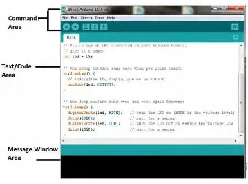
Figure 2.4: Screenshot of Arduino IDE. [2]
The Arduino IDE software is a set of instructions that informs the hardware on what to do and how to do it. The software interface is divided into three main parts:
Command Area: This is the area where menu items such as File, Edit, Sketch, Tools, Help and Icons like Verify Icon for verification, Upload Icon for uploading the programme, New, Open, Save and Serial Monitor used for sending and receiving of data between the Arduino and the IDE.
Text Area: This is where code writing is done. It uses a simplified version of C++ programming language that makes it easier to write programmes, which is also called a sketch. When writing the code there are mainly two important parts :
o The setup function: Before the setup variables need to be initialised so that
![Figure 2.1: Road fatalities by road user group. [1]](https://thumb-ap.123doks.com/thumbv2/123dok/471563.51561/20.612.194.458.453.649/figure-road-fatalities-road-user-group.webp)
![Figure 2.2: Arduino Uno prototype board [2]](https://thumb-ap.123doks.com/thumbv2/123dok/471563.51561/22.612.139.518.73.312/figure-arduino-uno-prototype-board.webp)