ISSN: 1693-6930
accredited by DGHE (DIKTI), Decree No: 51/Dikti/Kep/2010 523
A Thermoelectric Generator Replacing Radiator for
Internal Combustion Engine Vehicles
Nyambayar Baatar1, Shiho Kim2
1Department of Electrical Engineering, Chungbuk National University 2
School of Integrated Technology and Yonsei Institute of Convergence Technology Yonsei UniversitySongdo, Incheon 406-840, Korea Ph./Fax: +82-327495836
e-mail: [email protected], [email protected]
Abstrak
Pada makalah ini diusulkan dan dikembangkan sebuah generator termoelektrik (TEG) temperatur rendah menggunakan pendingin air mesin untuk kendaraan ringan. Hasil eksperimen dari kendaraan uji, yang mana ukuran mesin adalah sekitar 2,0 liter, menunjukkan bahwa purwarupa generator termoelektrik yang dibuat dapat membangkitkan lebih dari 75W untuk kondisi pengemudian 80 km/jam, dan daya output adalah sekitar 28W selama kondisi diam. Hasil penelitian menunjukkan bahwa TEG yang diusulkan dapat menggantikan radiator konvensional tanpa penambahan pompa air atau peranti mekanis, kecuali untuk komponen dasar sistem pendingin air radiator.
Kata kunci: generator termoelektrik, kendaraan ringan, pendingin air mesin, pipa panas
Abstract
We have proposed and developed a low temperature thermoelectric generator (TEG) using engine water coolant of light-duty vehicles. Experimental results from test vehicle, of which engine size is about 2.0 liters, show that fabricated prototype Thermoelectric Generator generates more than 75W for driving condition of 80 km/hour, and output power is about 28W during idle condition. The proposed TEG can replace conventional radiator without additional water pumps or mechanical devices except for basic components of legacy water cooling system of radiator.
Keywords: engine water coolant, heat pipe, light-duty vehicles, thermoelectric generator
1. Introduction
Conversion of waste heat to electricity using thermoelectric generators(TEG) in internal combustion engine (ICE) powered vehicles has been focused as a green energy technology to improve fuel economy and consequently to reduce emission of the green house gas of CO2 [1-4].
TELKOMNIKA Vol. 9, No. 3, December 2011 : 523 - 530
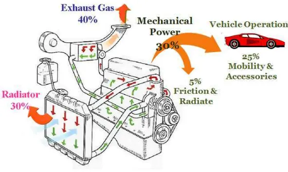
Only 30% of the fuel combustion energy is converted to mechanical energy, while about 40% is wasted through exhaust gas, and waste heat of engine coolant constitutes up to 30% of the fuel consumption energy [1-2]. Only about 25% of the fuel consumption energy is used for vehicle operations due to frictional losses. A recent study revealed that the fuel economy of ICE vehicles can be increased by up t0 20 percent simply by capturing the waste heat of gas and conveting about 10% of it to electricity[1-2]. Every major automobile manufacturer is working with waste heat recovery system for improving the fuel economy of ICEV, and some of them are trying to develop Thermoelectric Hybrid Electric vehicles [1-3]. A hybrid vehicle using Rankine cycle co-generation system has been developed, increasing overall engine efficiency by 3.8% in 100km/h constant driving mode [3]. In order to utilize advantages and benefits of an high temperature of exhaust gas which is more than 500˚C near the engine manifold, most of automotive manufacturing companies are working for developing thermoelectric generator systems using only exhaust gas [1-3]. Since the engine coolant is an important source of waste energy, we need to develop thermoelectric generators using engine coolant as well as exhaust gas to improve the overall fuel economy. Figure 2 shows a configuration of dual generation waste heat recovery system for passenger vehicles [5-6].
Figure 2. Dual thermoelectric generation waste heat recovery system [5-6]
We have proposed and developed a low temperature thermoelectric generator using engine water coolant of passenger vehicles, of which engine size is about 2.0 liters. We tried to substitute conventional radiator for proposed TEG without additional water pumps or mechanical devices except for basic components of legacy water cooling system based on radiator. We also proposed a SPICE equivalent electrical model of the engine coolant thermoelectric generator.
2. Proposed Engine Coolant Termoelectric Generator
We have aimed to substitute conventional radiator for proposed TEG without additional water pumps or mechanical devices except for basic components of legacy water cooling system of radiator. Since the proposed thermoelectric system generates electricity from waste heat of coolant, it takes a heat out of the engine coolant.
(a) by proposed thermoelectric g cooling system.
e illustration with detailed parts (a) and side view (b erator. (c) The inner structure of hot side block. The rection of coolant flowing Dimension is in mm scale.
has inlet and outlet ports of engine coolant to l g plates and hot side block are placed like a sa n be attached on both side of the hot side block. Th ctive surface area of the hot side block as illustrat side block with partition-walls enables proper trans thermoelectric modules and uniform distribution lectric generator. The Cold side of proposed TEG h t pipes and a heat spreader. The dimension of f H) × 740mm(L), which is same length and almost cle. 72 thermoelectric modules and 128 heat pipe thermoelectric generator. We can replace the con generator without additional devices or redesign
EG has an efficient heat spreading structure consis pe is a heat transfer device that combines the p
TELKOMNIKA Vol. 9, No. 3, December 2011 : 523 - 530
The heat energy is transferred from cold side block to heat sink by the internal processes of heat pipe. At the hot interface within a heat pipe, pressurized fluid in contact with a thermally conductive solid surface turns into a vapor by absorbing the latent heat of that surface. The vapor naturally flows through the system at atomic speeds, because of the low pressure, and condenses back into a liquid at the cold interface, releasing this latent heat. The liquid then returns to the hot interface through either capillary action or gravity action where it evaporates once more and repeats the cycle.
3. Expermental Results
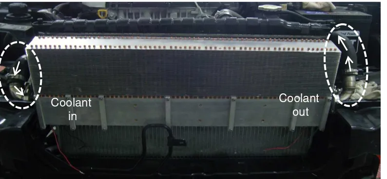
The proposed TEG system was fabricated and mounted on a test vehicle with engine size of about 2.0 liters after radiator was eliminated as shown in Figure 4. The test vehicle is a remodeled ICE vehicle simulator having engine, front wheel drive-train and electric powder break system. We can simulate actual driving condition on the road using the test vehicle in an indoor experimental laboratory. During experiment, we placed 72 Bismuth telluride(Bi2Te3) thermoelectric(TE) modules with area of 4.0mm × 4.0mm to the TEG. The experiment was performed under both idle and driving condition of vehicle.
Figure 4. Fabricated prototype TEG mounted on the ICE vehicle with engine size of about 2 liters. Fabricated prototype TEG replaces radiator as a cooling device.
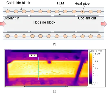
Figure 5 shows a structure and thermal imager for measuring temperature profile of TEG during operation. Infra red images were taken from the bottom part of the TEG. Figure 6 is a temperature profile across the Hot side block and Cold side block along with the strait line marked in Figure 5(b) The temperature profile was measured after the test vehicle was in steady state.In idle condition the temperature profile result of hot side block was ranged from 90˚C to 95˚C, and cold side temperature profile was about 70˚C. In this condition the temperature difference between hot side and cold side of the thermoelectric modules is about 25˚C.
In driving condition of 80km/hour, the temperature distribution of hot side block was from 95˚C to 100˚C , and cold side temperature profile was about 45˚C. In this condition the temperature difference between hot side and cold side of the thermoelectric modules is about 55˚C. The cold side temperature in driving condition of 80km/hour is lower than that of idle condition, thanks to an assistance of incoming cooling air flow since the vehicle is running. The radiator air-cooling fan of the test vehicle was off during experiment in the driving mode to make an equivalent condition.
Experiment results in the idle condition, the measured open-circuit voltage (OCV), short circuit voltage (ISC) and power at the maximum point were 30V, 3.8A, and 28.5 Watts,
Coolant
in
respectively. We used 72 thermoelectric modules (TEM) during experiments, so the maximum output power is about 0.4 W per module at the idle condition.
(a)
(b)
Figure 5. (a) Bottom side view of the proposed TEG. (b) Infra-red image when the vehicle of was operating in driving condition of 80 km/hour.
Figure 6 Temperature profile across the Hot side block and Cold side block along with strait line marked in Figure 5.(b)
Hot side block
Coolant in
Heat pipe
Cold side block
TEM
TELKOMNIKA Vol. 9, No. 3, December 2011 : 523 - 530
Figure 7. Simulation and experimental result of Voltage versus current characteristics of proposed TEG, when the vehicle was in idle and driving conditions.
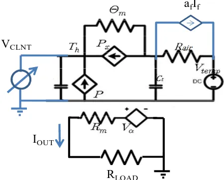
In driving mode, the increment of hot side temperature is about 5˚C, on the other hand, reduction of cold side temperature due to incoming air-cooling is about 25˚C. The measured OCV, ISC and maximum power point were 50V, 6A, and 75Watt, respectively. The maximum output power is about 1.04W per module at the driving condition.The electro-thermal behavior of a thermoelectric module has modeled as an equivalent electric circuit with model parameters of thermal resistance(Θm),Seebackcoefficient(αm),electric resistance(Rm), thermal capacitance and thermal resistance of heat spreader(Rair)[8]. Figure 8 shows a proposed electro-thermal equivalent electric model of an engine coolant thermoelectric generator. VCLNT is a heat supplied by engine coolant; andafIf is an incoming cooling air flow when a vehicle is running. During idle mode incoming air flow is zero and VCLNT is 368V, which is representation of absolute temperature of 95˚C. Measured Rm is about 8.0 Ω, andαm is 1.36V/˚C at idle condition and 0.95V/˚C at the driving condition.
Figure 8. SPICE equivalent electrical model of the engine coolant thermoelectric generator. WhereVαis α(Th-TC).
Maximum Power point tracking scheme and Lead-acid battery charging system for conventional ICE vehicle was reported [9]. The SPICE equivalent electrical model of the engine
a
fI
fR
LOADV
CLNTcoolant thermoelectric generator will be helpful to develop a battery charge system of both internal combustion engine vehicles and Hybrid Electric vehicles.
4. Discussions
The efficiency of the TEG in automotive applications can be estimated by [1, 4],
ε
=
where ZT is a figure of merit, and TH and TC are the hot-side and cold-side temperatures of the thermoelectric materials, respectively. We used Bi2Te3 TE modules with ZT ≈ 0.7. Calculated efficiency of the TEG is 3.2% and 10.0%, in the experimental condition of idle and driving mode, respectively.
Coolant flow speed for typical ICE vehicle is need to mechanically driven water pump vary between from 1.0 to 1.7 L/min/KW [10]. The maximum power of test vehicle is about 100kW. The flow rate of engine coolant is about from 100 to 170 L/min. Since about 30 percent of combustion energy is waste through engine coolant, the maximum waste power is about 30KW, which is huge amount of energy loss.
The output power of the fabricated TEG was only 75W at driving condition of 80Km/hour, the overall efficiency of electric power generation from waste heat of engine coolant is only about 0.4%, we estimate that the waste heat through engine coolant is about 18kW during the driving condition with 100 KW engine.
The overall efficiency is only 0.4%, it means that we still have a lot of room to regenerate electric energy from the waste heat of engine coolant. If we increase the number of thermoelectric module attached on the TEG, the output power can be increased significantly. Improvement of figure of merit of thermoelectric device is highly required for the automotive applications.
5. Conclusion
We have proposed and developed a low temperature thermoelectric generator using engine water coolant of passenger vehicles, of which engine size is about 2.0 liters. We also carried out the experimental and computational modeling works to demonstrate the performance of the proposed TEG. In the experimental results, maximum estimated output power from proposed TEG is about 75W and calculated efficiency of the TEG is about 10.0%, overall efficiency of electric power generation from waste heat of engine coolant is about 0.4% in the driving mode of 80km/h. The proposed TEG can replace conventional radiator without additional water pumps or mechanical devices except for basic components of legacy water cooling system of radiator.
Acknowledgment
This research was supported in part by the MKE, Korea, under the “IT Consilience Creative Program” support program supervised by the NIPA (NIPA-2010-C1515-1001-0001)
References
[1] Stabler F. Automotive Applications of High Efficiency Thermoelectrics. Proceedings of DARPA / ONR / DOE High Efficiency Thermoelectric Workshop. 2002: 1-26.
[2] Fairbanks J. DOE’s Launch of High-Efficiency Thermoelectrics Projects’. DEER Conference. 2004.
[3] Kadota M, Yamamoto K. Advanced Transient Simulation on Hybrid Vehicle Using Rankine Cycle System. SAE international. 2008.
[4] Bell L. Cooling, Heating, Generating Power and Recovering Waste Heat with Thermoelectric Systems. 2008; 321: 1457-1461.
[5] Park S, Yoo J, Kim S. Low and high Temperature Dual Thermoelectric Generation Waste Heat Recovery System for Light-Duty Vehicles. DEER Conference. 2009.
TELKOMNIKA Vol. 9, No. 3, December 2011 : 523 - 530
[7] Lineeykin S, Ben-Yaakov S. Modeling and analysis of thermoelectric modules. IEEE Transc. On Industrial Electronics. 2007; 43(2): 505-512.
[8] Kim R, Lai J, York B, Koran A. Analysis and design of Maximum Power point tracking scheme for thermoelectric battery energy storage system. IEEE Transc. On Industrial Electronics. 2009; 56(9): 3709-3716.
[9] Brace CJ, Burnham-Slipper H, Wijetunge RS, Vaughan ND, Wright K, Blight D. Integrated Cooling Systems for Passenger Vehicles. SAE international. 2001
[10] Kim S, Park S, Rhi S. A Thermoelectric Generator Using Engine Coolant for Light-Duty Internal Combustion Engine-Powered Vehicles. Journal of Electronic Materials. 2011; 40(5): 1-5.
![Figure 2. Dual thermoelectric generation waste heat recovery system [5-6]](https://thumb-ap.123doks.com/thumbv2/123dok/237131.502280/2.595.130.462.293.498/figure-dual-thermoelectric-generation-waste-heat-recovery.webp)