THE PERFORMANCE ANALYSIS OF HIGH SPEED
STEEL TOOL IN HIGH SPEED DRILLING.
RAZIF BIN MUDZLAN
B050810147
UNIVERSITI TEKNIKAL MALAYSIA MELAKA
This report submitted in accordance with requirement of the Universiti Teknikal Malaysia Melaka (UTeM) for the Bachelor Degree of Manufacturing Engineering
(Manufacturing Process) (Hons.)
by
RAZIF BIN MUDZLAN B 050810147 890727-14-6121
FACULTY OF MANUFACTURING ENGINEERING 2012
UNIVERSITI TEKNIKAL MALAYSIA MELAKA
BORANG PENGESAHAN STATUS LAPORAN PROJEK SARJANA MUDA
TAJUK: THE PERFORMANCE ANALYSIS OF HIGH SPEED STEEL TOOL IN HIGH
SPEED DRILLING
SESI PENGAJIAN: 2011/12 Semester 2
SayaRAZIF BIN MUDZLAN
mengaku membenarkan Laporan PSM ini disimpan di Perpustakaan Universiti Teknikal Malaysia Melaka (UTeM) dengan syarat-syarat kegunaan seperti berikut:
1. Laporan PSM adalah hak milik Universiti Teknikal Malaysia Melaka dan penulis.
2. Perpustakaan Universiti Teknikal Malaysia Melaka dibenarkan membuat salinan
untuk tujuan pengajian sahaja dengan izin penulis.
3. Perpustakaan dibenarkan membuat salinan laporan PSM ini sebagai bahan
pertukaran antara institusi pengajian tinggi. atau kepentingan Malaysia yang termaktub di dalam AKTA RAHSIA RASMI 1972)
I hereby, declared this report entitled “The Performance Analysis of High Speed Steel in High Speed Drilling” is the results of my own research except as cited in
references.
Signature : ……… Author’s Name : Razif Bin Mudzlan Date : 29 June 2012
This report is submitted to the Faculty of Manufacturing Engineering of UTeM as a partial fulfillment of the requirements for the degree of Bachelor of Manufacturing Engineering (Manufacturing Process). The members of the supervisory committee are as follow:
ABSTRAK
ABSTRACT
ACKNOWLEDGEMENT
TABLE OF CONTENT
List of Abbreviations and Nomenclature xii
CHAPTER 1: INTRODUCTION 1
2.1.5 Differentiation between Conventional and High Speed 9
2.3.2.2 Abrasive Wear 18
3.1.3 Determine Objectives and Scope of Project 24
3.1.4 Gather Information 24
3.1.5 Gantt Chart 24
3.2 Parameter and Controlled Condition 26
3.3 Performance Measured 27
3.5.4 Surface Roughness Tester 30
3.5.5 Horizontal Band Saw 31
3.6 Experiment Process 32
CHAPTER 4: RESULT & DISCUSSION 34
4.1 Introduction 34
4.2 Tool Wear 34
4.3 Surface Roughness 40
CHAPTER 5: CONCLUSION & RECOMMENDATIONS 44
LIST OF TABLES
2.1 Differentiation between Types of Speed 6
2.2 Differentiation between Conventional and High Speed 10
3.1 Gantt Chart 25
3.2 Drilling Cutting Parameters 26
3.3 Result Table at Constant Feed Rate 27
3.4 Result Table at Constant Speed 27
3.5 Process of Experiment 32
4.1 Flank Wear at Constant Feed Rate 36
4.2 Flank Wear at Constant Spindle Speed 38
4.3 Surface Roughness at Constant Feed Rate 41
LIST OF FIGURES
2.1 Conventional, High Speed and High Velocity Machining 6
2.2 Parts Of Twist Drills 7
2.3 Small (Low) and Big (High) Helix Angle 8
2.4 Differentiation of Tool Design 9
2.5 The Hardness of Various Tool Materials as A Function Of Temperature 12
2.6 Flank Wear versus Machining Time 14
2.7 Flank Wear versus Machining Time (Constant Speed) 14 2.8 Estimation of Tool Wear Based On the Cutting Speed and Feed Rate 15
2.9 Different Types of Wear 16
2.10 Optical Micrograph of Cross-Sectioned Hob Tooth after Cutting
Austenitic Stainless Steel 18
2.11 Typical Appearance of Abrasive Wear 19
2.12 Arithmetical Mean Roughness 20
2.13 Maximum Peak of Roughness (Ry) 21
2.14 Ten Point Mean Roughness (Rz) 21
3.1 Flow of the Project 23
3.2 CNC 5 Axis MAHO 29
3.3 HSS Twist Drill 29
3.4 Mitutoyo Surface Roughness Tester 30
3.5 Surface Roughness Measuring Process 31
3.6 Horizontal Band Saw 32
3.7 Workpiece after Drilling Process 34
4.1 Workpiece after Drilling Process 36
4.2 Graph of Tool Wear at Constant Feed Rate (200 mm/min) 37
4.7 Workpiece has been cut into Half 40 4.8 Graph of Surface Roughness at Constant Feed Rate 41
LIST OF ABBREVIATIONS AND NOMENCLATURE
UTeM - Universiti Teknikal Malaysia Melaka
CHAPTER 1
INTRODUCTION
1.1 Background of Project
The chip that produced is very hot can soften and smear against the tool, filling in microscopic crevices in its edge surface and the usage of sufficient coolant can flush away the chips while if the coolant is not used, it can cause the tool wear and shorten tool life. The common tool that used in high speed drilling is carbide because of the smaller grains resist wear with less of a sacrifice in toughness (American Machinist,2011). The usage of high speed steel in high speed drilling is very rare due to the properties. The results of tool wear and tool life of HSS by using high speed drilling is very different from carbides, ceramics, and also the other coated tool that can cause a very high cost.
1.2 Problem Statement
High speed drilling is a process that needs the spindle rotate very fast. Nowadays, many of industry applied high speed drilling in their manufacturing process. High speed drilling and also tooling has the relationship. The most common tools that used in high speed drilling are carbides and ceramics which can cause a rapid tool wear. High speed drilling will produce higher tool wear than the conventional method. The suitable speed and also the other parameter such as feed rate will make the tool life become longer and also the tool did not easily to wear. The rapid tool wear will make the tool life become shorter. The shorter tool life will increase the production cost because the tool is changed frequently to ensure that the part that produce is in quality. The focus tool that used in this project is HSS tool. HSS has now used for many years because the characteristic itself that resist to fracture, high toughness, wide range of roughing and also good for interrupted cuts (Kalpakjian and Schmid, 2010). Based on the characteristic of HSS that stated by Kalpakjian and Schmid, HSS can be used in high speed drilling process, but need to study the tool wear and also the hole quality including the surface roughness.
1.3 Objectives
The objectives for analysis high speed drilling with HSS tools are:
(a) To study the effect of high speed drilling process on tool wear.
(b) To investigate the influence of cutting speed on surface roughness in high speed drilling.
1.4 Scope of Project
The research was conducted within the following limits:
(a) Commercially available High speed Steel twist drill bit of 7 mm diameter. (b) Work material used was Aluminium 6000 series.
(c) High speed range used are between 10,000 rpm to 18,000 rpm. (d) The drilling process is not used any lubricant.
(e) The effect of high speed drilling will be based only on surface roughness and tool wear.
1.5 Report Outline
CHAPTER 2
LITERATURE REVIEW
2.1 Manufacturing Process
The manufacturing process that is used in this project is high speed drilling where the speed of this process is different from the conventional drilling.
2.1.1 High Speed Drilling
speed of spindle that exceeds 10,000 rpm, the drill and also the tool holder can be critical (American Machinist,2011).
Table 2.1: Differentiation between type of speed (Kalpakjian and Schmid, 2010).
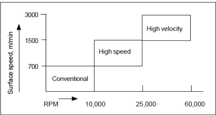
Type of speed Speed (m/min)
High Speed 600 – 1,800
Very High Speed 1,800 – 18,000
Ultra high Speed 18,000
Based on the table above, there is differentiation between the types of speed. For this project, we used high speed drilling which is 600 to 1800 m/min. Now, spindle rotational speeds in machine tools can range up to 50,000 rpm (Kalpakjian and Schmid, 2010). Sharma (2011) stated that the high speed machining starts from 700 to 1500 m/min. However, the spindle speed depends on the workpiece material that used. (Sharma, 2011).
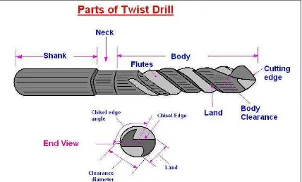
2.1.2 Twist Drills
The most common type of drill used today is a twist drill. This type of drill is made with two or more flutes that used for removal of chips and also allow lubricant or coolant to get down to the cutting edge. It's also made from two or more cutting lips and also has many varieties of design.
Figure 2.2: Parts of twist drill.
2.1.3 High and Low Helix Drills
High or low helix drill is based on the rake angle of the drills either it is small or large. High helix drills also known as fast spiral drills are designed to remove chips from the deep hole of the workpiece. High helix drill means the rake angle of the drill is large that will make this drill suitable for soft metals such as aluminium and also mild steel (Kibbe et al, 2010). This type of helix also suitable for thin material. Low helix drills also known as slow spiral drills can stand more torque because of it is more rigid than standard helix drills. The flutes of this low helix drills do not remove chips well from deep holes, but large chip space allows maximum drilling efficiency in shallow holes (Kibbe et al, 2010). Below is the figure that shows the high and low helix drill.
Figure 2.3: Small (low) and big (high) helix angle (Fu et al, 2010).
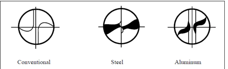
2.1.4 Drill Design
Figure 2.4: Differentiation of tool design (Sharma, 2011).
The reason of the design is to optimize chip formation and evacuation to prevent welding of the aluminium to the chisel, which due to excessive heat produced (Sharma, 2011). The spiral angle also different to remove the chips quickly. The most effective design for drilling aluminium is a slower spiral of 12 degrees at speed about 10,000 rpm (Sharma, 2011). This result is got after conduct some test.
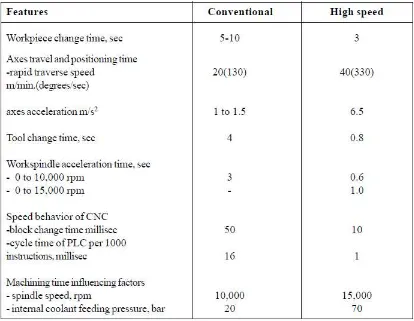
2.1.5 Differentiation between conventional and high speed
Table 2.2: Differentiation between conventional and high speed (Sharma, 2011)
2.2 Tool Material – High Speed Steels (HSS)
This project is to study the tool wear and also tool life of HSS by using high speed drilling process. HSS is the common tool that used in the drilling process.
2.2.1 Definition