‘I/We* hereby declare that this composition has been read and on my/our* opinion this composition is acceptable from the scope and the quality for being awarded Bachelor
Degree of Mechanical Engineering (Design and Innovation)’
Signature :………
1st Supervisor’s Name :………
Date :………
Signature :………
2nd Supervisor’s Name :………
Date :………
DESIGN AND ANALYSIS OF MECHANICAL HAND USING COMPUTER AIDED MECHANISM DESIGN
(CAMD) TECHNIQUE
MUHAMAD KHALIS BIN RAMLI
This thesis submitted in partial fulfillment of the requirements for the degree of Mechanical Engineering
(Design & Innovation)
Faculty of Mechanical Engineering Universiti Teknikal Malaysia Melaka
ii
“I confess that this work is the result of my own investigations. All sections of the text and results, which have been obtained from other
workers/sources, are fully referenced”
Signature :………….……… Name : Muhamad Khalis bin Ramli
iii
iv
ACKNOWLEDGEMENT
“In The Name of Allah, The Merciful, The Beneficent”
Glory to Allah S.W.T, The Most Gracious, The Most Merciful, and peace is upon His messenger Holy Prophet Muhammad S.A.W. All the worship belongs to only Allah. We seek refuge with Allah from the wickedness within and from the evil deeds. We also praised to Allah S.W.T for giving us courage, time, and knowledge in completing this thesis for my bachelor project.
I would like to take this opportunity to thank my project supervisor, Mr. Faiz bin Redza for his invaluable guidance, assistance, and support throughout this work. Under his supervision, many aspects regarding on this project has been explored, and with knowledge, idea and support received from him, this thesis can be presented in the given time.
I’d also like to especially thank my family for their patience, support, and words of encouragement that have been crucial to this thesis completion. My parents, Mr. Ramli bin Jantan, and Mrs. Khatijah binti Johar, and also to my sister, Ms. Rosilawati binti Ramli.
v
ABSTRACT
vi
ABSTRAK
vii
TABLE OF CONTENT
CHAPTER TOPIC PAGE
CONFESSION ii
DEDICATION iii
ACKNOWLEDGEMENT iv
ABSTRACT v
ABSTRAK vi
TABLE OF CONTENT vii
LIST OF TABLES xi
LIST OF FIGURES xii
LIST OF APPENDIX xvii
CHAPTER I INTRODUCTION 1
1.1 Objective 1
1.2 Scope 2
1.3 Problem Statement 2
CHAPTER II LITERATURE REVIEW 4
2.1 Related Work 4
2.2 High Level Grasp Synthesis 4
viii
CHAPTER TOPIC PAGE
2.3.1 Theoretical Bounds on the Necessary and Sufficient Number of Contacts Required for Form- and Force-Closure
8
2.3.2 Quality Measures 9
2.3.3 Contact-level Synthesis Algorithms 10 2.3.4 Hand-level Grasp Synthesis Systems 11 2.3.5 Optimal Force Distribution 13
2.4 LEGO MINDSTORMS NXT 14
2.4.1 Introduction 14
2.4.2 The NXT 15
2.4.3 Output (motor) ports and the USB port
16
2.4.4 The input (sensor) ports 17
2.4.5 The servo motor 18
2.4.6 The Sensors 19
2.4.6.1 Passive Sensors 19
2.4.6.2 Digital sensor 23
2.5 LEGO MINDSTORMS NXT pieces 25
2.5.1 Classifying the pieces 26
2.6 Software Description 29
2.6.1 SolidWorks 2007 29
2.6.2 COSMOSMotion 30
2.6.2.1 User Interface 31
2.6.2.2 Constraints 32
2.6.2.3 Forces 33
ix
CHAPTER TOPIC PAGE
CHAPTER III METHODOLOGY 35
3.1 Methodology Flow Chart 35
3.1.1 Literature Review 37
3.1.2 Designing 37
3.1.3 Analysis 37
3.1.4 Result and Discussion 38
3.1.5 Conclusion 38
CHAPTER IV BUILDING LEGO MINDSTORMS NXT PIECES
4.1 The Beams 39
4.1.1 The Straight Beam 41
4.1.2 The Angled Beam 42
4.2 The Connectors 43
4.2.1 The Axles 46
4.2.2 The Pegs 48
4.3 The Gears 48
4.3.1 Spur Gears 50
4.3.2 Turntable Gears 50
CHAPTER V DETAILED DESIGN 52
5.1 Introduction 52
5.2 Part Design 52
5.2.1 Mechanical Base 54
5.2.2 Mechanical Arm 55
5.2.3 Mechanical Hand 56
x
CHAPTER TOPIC PAGE
CHAPTER VI ANALYSIS DESIGN 60
6.1 Introduction 60
6.2 Analysis with COSMOSMotion 2007 60
6.2.1 Procedure of analysis using COSMOSMotion
61
6.2.2 Motion after simulation 66
CHAPTER VII RESULT AND DISCUSSION 69
7.1 Results with COSMOSMotion 2007 69
7.1.1 Velocity Analysis 69
7.1.2 Acceleration 73
CHAPTER VIII CONCLUSION & RECOMMENDATION 78
8.1 Conclusion 78
8.2 Recommendation 79
REFERENCES 80
xi
LIST OF TABLES
NO. TITLE PAGE
2.1 The Default Sensor Ports On The NXT 18
4.1 The NXT Beams 40
4.2 The Connectors In The NXT Set 43
xii
LIST OF FIGURES
NO. TITLE PAGE
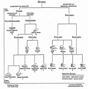
2.1 Taxonomy Of Human Grasps By Cutkosky And Wright’s (1986)
5
2.2 NXT Programming With Four Types Of Sensor And Three Servo Motor
14
2.3 The NXT, A LEGO MINDSTORMS Microcomputer 15
2.4 Output Ports A, B, C; And The USB Port 16
2.5 The Input Ports On The NXT 17
2.6 The MINDSTORMS NXT Servo Motor 18
2.7 The Built-In Rotation Sensor Or Tachometer 19
2.8 The MINDSTORMS NXT Touch Sensor 20
2.9 Functions Of The Touch Sensor 21
xiii
NO. TITLE PAGE
2.11 The Comparison Between When Human Eyes See The Light and When Robot Sees Using The Light Sensor
22
2.12 The MINDSTORMS NXT Sound Sensor 22
2.13 The MINDSTORMS NXT Ultrasonic Sensor 24
2.14 The Ultrasonic Sensor Sends and Then Receives A Sound Wave to Determine The Distance Between Itself and an Object
24
2.15 The Types and Quantities Of Pieces In The NXT Set 26
2.16 The Beams In The NXT Set 27
2.17 The Connectors In The NXT Set 27
2.18 The Gears In The NXT Set 28
2.19 The Miscellaneous Elements In The NXT Set 28
2.20 SolidWorks Official Logo 29
2.21 COSMOSMotion Logo 30
3.1 Methodology Flow Chart 36
xiv
NO. TITLE PAGE
4.2 A Module (M) is about 8 Mm, the Distance from The Centre Of One Hourglass-Shaped Depression to The Center Of One Adjacent Depression
42
4.3 The 7M Perpendicular Angled Beam 43
4.4 The 7M Axle 47
4.5 The Bushing And Half-Bushing are Assistants to The Axles
47
4.6 3M Friction Peg 48
4.7 The 8t Gear 50
4.8 The Turntable Gear 51
5.1 Mechanical Base Assembly 54
5.2 The Servo Motor Was Located In The Center of The Mechanical Base Assembly
55
5.3 The Assembly of Mechanical Arm 56
5.4 The Assembly of Mechanical Hand 57
5.5 Full Assemblies That Joint From Three Small Parts Assemblies
xv
NO. TITLE PAGE
5.6 The Mechanical Hand Want to Grasp The Red Ball 59
6.1 Add-Ins Tab 61
6.2 “Motion” Menu 62
6.3 Intellimotion Builder 62
6.4 Mechanical Hand 64
6.5 Orange Motor and Motor is the Revolute Between These Parts
65
6.6(a) First Description about Simulation when The Mechanical Hand to Grasp The Red Ball
66
6.6(b) Second Description about Simulation when The Mechanical Hand to Grasp The Red Ball
67
6.6(c) Third Description about Simulation when The Mechanical Hand to Grasp The Red Ball
67
6.6(d) Fourth Description about Simulation when The Mechanical Hand to Grasp The Red Ball
68
6.6(e) Fifth Description about Simulation when The Mechanical Hand to Grasp The Red Ball
xvi
NO. TITLE PAGE
7.1 CM Velocity Beam Angled Below 70
7.2 CM Velocity Beam Angled Upper 71
7.3 CM Velocity 8t Gear 71
7.4 CM Velocity 24t Gear 72
7.5 CM Velocity Orange Motor 73
7.6 CM Acceleration Beam Angled Below 74
7.7 CM Acceleration Beam Angled Upper 74
7.8 CM Acceleration 8t Gear 75
7.9 CM Acceleration 24t Gear 76
xvii
LIST OF APPENDIX
NO. TITLE PAGE
A PROJECT PLANNING 84
B ENGINEERING DRAWING 86
1
CHAPTER I
INTRODUCTION
Grasping is one of the primary ways for a robot to interact with objects in its environment. Assembly line robots use simple end-effectors such as suction cups or parallel jaw grippers to accomplish pick and place tasks with a high degree of reliability. However, the factory environment is highly structured, and each robot usually only grasps one type of object until it is reprogrammed to handle another object type. This reprogramming is done simply using operator knowledge or more recently using software to automatically pick the contact points (Smith et al., 1999). As robots are being required to work in more unstructured environments, such as service robots in the home, bomb disposal robots, and robots used in space missions, more general purpose hands are being designed that are capable of grasping and manipulating a much wider range of objects. Hence, in these projects, one model of mechanical hands will be constructing by using LEGO MINDSTORMS model to study the movement mechanism by grasp any objects. This project also can put something more clearly about the mechanical hand in diurnal life.
1.1 Objective
2
using the touch sensor to trace object, the touch sensor will work to take the object and move it from one place to another place.
1.2 Scope
Following are the scope of the projects to make sure this project is successful:
i. Design mechanical hand by using 3D CAD software, such as SolidWorks 2007 and Lego Digital Designer.
ii. Study the mechanism of mechanical hand by using CAMD techniques, likes COSMOSMotion.
iii. Then, use the COSMOSMotion to do the analysis about the acceleration and the velocity. To do the simulation by using the same software to investigate the mechanical hand when grasp object.
iv. Also, use COSMOSMotion to make the animation how it works. v. Analyze and suggest improvement of mechanical hand mechanism so
that the model must be in the best condition and able to function in a long period of time.
1.3 Problem Statement
3
Apart from that is to determine which software can give the accurate value when do the analysis. For example, between SolidWorks and ADAMS, which software can give the actual value with the origin condition?
Other than that is how to identify the limitation factors of the model, such as the types of objects that can be grasped, the object’s minimum and maximum weight, and other factors. For example, the simulation data taken from COSMOSWorks Designer and COSMOSMotion, which can give the accurate data with the real condition when grasp the object.
4
CHAPTER II
LITERATURE REVIEW
2.1 Related Work
Because of the versatility of the human hand, there has been a great deal of research devoted to studying the hand and to building robotic hands that can mimic some of its functionality. This thesis focuses on grasp analysis as well as simulation, and this chapter reviews the significant body of work in these areas. A clear division of approach in grasping was illustrated by Mishra and Silver, (1989) who separated the previous work into higher level of physiological studies of the human hand and lower level studies of the mechanics of contact. While this thesis is primarily concerned with simulating and analyzing the grasping mechanics, the synthesis techniques of the higher level approach cannot be ignored. This chapter begins by reviewing these techniques, and then it presents the large body of previous work concerned with the mechanics of grasping which is further divided into several sub-areas. Finally, the chapter concludes by reviewing research in the area of general robotic simulation.
2.2 High Level Grasp Synthesis
5
[image:23.595.145.493.321.675.2]enormous set of possible hand configurations. However, in choosing their own grasps, humans unconsciously simplify the task to selecting one of the only a few different prehensile postures appropriate for the object and for the task to be performed. Medical literature has attempted to classify these postures into grasp taxonomies as seen in McBride (1942), Griffiths (1943), and Slocum and Pratt (1946), but the most well known grasp taxonomy was proposed by Napier (1956). His work establishes the fundamental differences between power grips, which envelop the object and offer maximum manipulability. Cutkosky and Wright (1986) extended this classification to the types of grips needed a manufacturing environment and examined how the task and object geometry affect the choice of grasp. Their tree-like classification can be seen in Figure 2.1.
Figure 2.1: Taxonomy of human grasps by Cutkosky and Wright’s, (1986)
6
with respect to two virtual fingers which apply opposing forces on the objects, and only later maps these virtual fingers onto physical fingers based on object characteristics. The basic oppositions of the virtual fingers are divided into pad opposition, which is between the thumb and finger pads and used for precision type grasps, palm opposition, which is between the palm and the digits and used for power type of grasps, and side opposition, which is between the thumb and the side of the index finger and is compromise between the flexibility of the pad opposition grasps and the stability of the palm opposition grasps. Lyons (1985) uses the concept of the virtual fingers in his development of a grasp index that that selects a grasp on the basis of two object characteristics, shape, and size, whether the grasp should be firm or not and whether the grasp should be precise or not. Unfortunately, his categories are quite broad and make it difficult to create a grasp tailored to specific objects.
Stansfield (1991) built these classifications into a rule based system that, when given a simplified object description from a vision subsystem, will provide a set of possible hand preshapes and reach directions for the pre-contact stage of grasping. However, many problems are left unsolved. She only examines five possible approach directions, she does not try to choose the best grasp from this set of possibilities, and for any grasp that is chosen, the hand simply closes its fingers; no attempt is made to optimize the grasp for stability.