._UTeM
UNIVERSITI TEKNIKAL MALAYSIA MELAKAUNIVERSITI TEKNIKAL MALAYSIA MELAKA
DESIGN AND ANALYSIS OF HAND AND WRIST SUPPORT
DEVICE
This report submitted in according with requirement of the Universiti Teknikal Malaysia Melaka (UTeM) for the Bachelor Degree of Manufacturing Engineering
(Manufacturing Design)
MOHAMAD NAZRIN BIN MOHD YUSOFF
B051110071
UNIVERSITI TEKNIKAL MALAYSIA MELAKA
UHrvERSITI TEKHIKAL MALAYSIA MELA
BORANG PENGESAHAN STATUS LAPORAN PROJEK SARJANA MUDA
TAJUK: Design and Analysis of Hand and Wrist Support Device
SESI PENGAJIAN: 2013/14 Semester 2
Saya MOHAMAD NAZRIN BIN MOHD YUSOFF
mengaku membenarkan Laporan PSM ini disimpan di Perpustakaan Universiti Teknikal Malaysia Melaka (UTeM) dengan syarat-syarat kegunaan seperti berikut: 1. Laporan PSM adalah hak milik Universiti T eknikal Malaysia Melaka dan penulis. 2. Perpustakaan Universiti Teknikal Malaysia Melaka dibenarkan membuat salinan
untuk tujuan pengajian sahaja dengan izin penulis.
3. Perpustakaan dibenarkan membuat salinan laporan PSM ini sebagai bahan pertukaran antara institusi pengajian tinggi.
4. **Sila tandakan ( ./)
,I
SULIT
TERHAD
D
D
0
TIDAK TERHADAlamat Tetap:
(Mengandungi maklumat yang berdarjah keselamatan atau kepentingan Malaysia sebagaimana yang termaktub dalam AKTA RAHSIA RASMI 1972)
(Mengandungi maklumat TERHAD yang telah ditentukan oleh organisasi/badan di mana penyelidikan dijalankan)
Disahkan oleh:
セセ@
NO 18 LORONG HJ MD SAMAN,
DR. SHAJAHAN B\N MAIDIN
Pensyarah Kanan
JALAN DATO KUMBAR, 05300 ALOR STAR, KEDAH
Fakulti Kejuruteraan Pembuatan Universiti Teknikal Malaysia Melaka
Tarikh: 2o 'Ju.N i .2-0\
•• Jika Laporan PSM ini SULIT atau TERHAD, sila lampirkan surat daripada pihak berkuasa/organisasi berkenaan dengan menyatakan sekali sebab dan tempoh laporan PSM ini perlu dikelaskan sebagai SULIT atau TERHAD.
DECLARATION
I hereby, declared this report entitled "Design and Analysis of Hand and Wrist Support Device" is the results of my own research except as cited in references .
Signature Author's Name Date
...
ᆬNセ@
... .
NセセNセセセNセNセ@
••セNセ
QZMA@
...
セヲセ@
..セA_@
..
yセセセセゥ[@
APPROVAL
This report is submitted to the Faculty of Manufacturing Engineering of UTeM as a partial fulfillment of the requirements for the degree of Bachelor of Manufacturing Engineering (Manufacturing Design) (Hons.). The member of the supervisory is as follow:
] セ ᆬNセ
(Project Supervisor)N@
OR. SHAJAHAN BIN MAIDIN
Pensyarah Kanan
Fakutti Kejuruteraan Pembuatan Universiti Teknikal Malaysia Melaka
ABSTRAK
Solidwork. keputusan analisis menunjukkan bahawa tekanan rekabentuk tangan dan pergelangan tangan sokongan yang dihasilkan oleh FDM adalah selamat untuk digunakan berdasarkan faktor keselamatan adalah lebih tinggi daripada 1.
ABSTRACT
DEDICATION
I dedicate this project to my family, friends and lecturers. I am able to accomplish the goals and objectives of this project is all thanks to everyone for the time and knowledge they have given me throughout the project.
ACKNOWLEDGEMENT
TABLE OF CONTENTS
Abstrak Abstract Dedication
Acknowledgement Table of Content List of Figures List of Tables
List Abbreviations, Symbols and Nomenclatures
CHAPTER 1: INTRODUCTION
1.1 Background of research 1.2 Introduction
1.3 Problem statement 1.4 Objective
1.5 Scope of project
CHAPTER 2: LITERATURE REVIEW
2.1 Introduction
2.2 Human hand and wrist 2.3 Common injuries
2.4 Problems with previous bracing system. 2.5 Types of casts and splint
2.6 Principle and goal of splinting 2.6.1 Immobilization splints 2.6.2 Mobilizing splints
2.7 Categories of splint which immobilize and mobilize 2.8 Existing Product
2.8.1 Wrist Splint
2.8.2 Flexible wrist splint 26
2.8.3 Other patents design 28
2.9 Summary 29
2.10 Introduction prototypes 30
2.11 Types of prototypes 31
2.12 Additive manufacturing 32
2.12.1 Advantage of Additive Manufacturing 33
2.12.2 Fundamental of Additive Manufacturing 33
2.12.3 Additive Manufacturing System 36
2.12.4 Additive Manufacturing Technique 36
2.13 Fused Deposition Modeling (FDM) 39
2.14 FDM process 40
2.14.1 Process begins with 30 CAD data in STL file format. 41
2.14.2 STL data is "sliced" with software. 42
2.14.3 Layer by layer construction. 43
2.14.4 Cleaned off completed parts are removed and support material. 44
2.15 Applications FDM 45
2.16 Advantages of FOM 45
2.17 Disadvantages of FDM 46
2.18 Introduction Reverse Engineering 47
2.19 30 Digitizing process 49
2.30 Summary 51
CHAPTER3:METHODOLOGY
3.1 Introduction 52
3.2 Identify problem statement 55
3.3 Collecting Data 55
3.3.1 Questionnaire 56
3.3.2 Survey 56
3.5.2 Concept Screening 3.5.3 Concept Scoring 3.6 Test and analysis
CHAPTER 4: RESULT AND DISCUSSION 4.1 Introduction
4.2 Flow Chart of Project Activity 4.3 Survey
4.3.1 Need Statement from Questionnaire 4.3.2 Interpretation
4.3.2.1 Questionnaire Part A 4.3.2.2 Questionnaire Part B 4.3.2.2 Questionnaire Part C 4.3.2.3 Summary of Survey 4.4 Quality Function Deployment
4.4.l House of Quality
4.4.2 Explanation data from House of Quality 4.4.3 Product Specification
4.4.4 Concept Generation 4.4.5 Concept Selection
4.4.5.1 The Concept Screening. 4.4.5.2 The concept scoring. 4.5 Design Development
4.6. Faro arm
4.7 Scanning Procedures
4.8 The Improvement Process of CAD Drawing 4.8.1 Geomagic Studio 10
4.8.2 Improvement Process 4.9 Redesign Process
4.9.1 Redesign 4.10 CAD Drawing Model
4.10.1 Supporter wrist
4.10.2 Supporter Arm
4.11 Detail Drawing
97
100
4.12 Additive Manufacturing Processes I 02
4.12.1 Convert CAD Data into Stereolithography {STL) Fonnat I 02
4.12.2 FDM Process 103
4.13 Testing and Analysis 106
4.15 Summary 110
CHAPTER 5: CONCLUSION AND RECOMMENDATION
5. I Conclusion 5.2 Recommendation
REFERENCES APPENDIX
112 113
LIST OF FIGURES
Figure 1.1: Classification of fractures of the phalanges 2
Figure 1.2: Example of hand wrist bones 3
Figure 1.3: Layer of cast 5
Figure 1.4: Example cast for broken hand using plastic of paris 6
[image:14.524.72.453.165.708.2]Figure 2.1: Hand Anotomy 9
Figure 2.2: Anatomy of the wrist. 11
Figure 2.3: Example of cast saw. 13
Figure 2.4: Diagram showing how a fracture is subjected to a three point force
applied through a moulded cast. 16
Figure 2.5: Moulding also helps to prevent rotation and the rigid form of the cast will exert an even hydraulic support around the fracture site. 17
Figure 2.6: Example fiberglass cast 18
Figure 2. 7: Example static splint Figure 2.8 Example dynamic splints. Figure 2.9: Example plaster of Paris Figure 2.10: Example of static progressive Figure 2.11: Wrist Splint
Figure 2.12: Flexible Wrist Splint Figure 2.13: Flexible Wrist Splint
Figure 2.14: Example of hand and wrist splint Figure 2.15: Example ofhand and wrist splint Figure 2.16: Example product prototypes
Figure 2.17: Example of additive manufacturing product. Figure 2.18: Example of rapid prototyping wheel
Figure 2.19: FDM Machine Figure 2.20: Example CAD Model Figure 2.21: Example Sliced data Figure 2.22: Layer by layer construction Figure 2.23: Cleaned off complete part
Figure 2.24: Example of the sequences of the reverse engineering
Figure 2.25: Developed RE methodology integrated with CAD/CAE and FEA
for optimised RT 49
Figure 2.26: (a) Scanning machine configuration ("Replica"),
(b) 30-scanning laser digitiser principle 50
Figure 3.1: Methodology Chart 54
Figure 4.1: Flow Chart of Project Activity 63
[image:15.524.76.462.16.726.2]Figure 4.2: Gender 67
Figure 4.3: Percentage by Faculty 68
Figure 4.4: Bar Chart for hear about device support hand or wrist in 69 existing markets
Figure 4.5: Pie chart for where usually hear about the device. 69
Figure 4.6: Percentage that have a hand support device. 70
Figure 4.7: Question C ifthe respondent selected "YES," 71
Figure 4.8: Ergonomic 72
Figure 4.9: Method of Installation 72
Figure 4.10: Light 73
Figure 4.11: Comfortable 74
Figure 4.12: Easily Assemble and disassembled 74
Figure 4.13: No Interfere with the running 75
Figure 4.14: Not a bodily injury on another and the surrounding during use. 75
Figure 4.15: Have aesthetic value 76
Figure 4.16: House of Quality 78
Figure 4.17: Concept 1 81
Figure 4.18: Concept 2 82
Figure 4.19: Concept 3 82
Figure 4.20: Concept 4 83
Figure 4.21: Concept 5 83
Figure 4.22: Apparatus Faro arm 87
Figure 4.23: Function Faro Arm 88
Figure 4.24: Hand statue 89
Figure 4.28: Geomagic Studio l 0 Figure 4.29: Fill hole process Figure 4.30: Rough surface process Figure 4.31 : Solidwork 2013 Figure 4.32: Supporter wrist Figure 4.33: Supporter arm Figure 4.34: Full Assembly Figure 4.35: Full Assembly
Figure 4.36: Detail Drawing for Arm Support Figure 4.37: Detail Drawing for Wrist Support Figure 4.38: Arm support for STL file
Figure 4.39: Wrist support for STL file
Figure 4.40: 3D Modelling before transfer to STL file
Figure 4.41: Software FDM before transfer to FDM Machine. Figure 4.42: Block diagram of the FDM machine.
Figure 4.43: Final Product Figure 4.44: Ultrasonic tank
Figure 4.45: Factor of safety for arm support. Figure 4.46: Factor of safety for wrist support
LIST OF TABLES
Table 4.1: Respondent Background
Table 4.2: Detail Information
Table 4.3: Final Specification
Table 4.4: Concept Screening
Table 4.5: Concept Scoring
Table 4.6: Material properties for ABS plastic
64
65
80
85
86
AM BPM BASS CAD CAM DMD FEA FDM HOQ LOM PLT MJM QFD RE STL SLS SGC 3DP SDM
voe
µLIST OF ABBREVIATTION, SYMBOL, AND
NOMENCLATURE
Additive Manufacturing
Ballistic particle manufacturing
Break Away Support System
Computer aided design
Computer aided manufacturing
Direct Metal Deposition
Finite Element Analysis
Fused Deposition Modeling
House of quality
Laminated object manufacturing
Pares lamination Technology
Multi-Jet Modeling System
Quality function development
Reverse engineering
Stereolitography
Selective laser sintering
Solid ground curing
Three Dimensional Printing
shaped deposition manufacturing
Voice of customer
Micro
CHAPTER 1
INTRODUCTION
1.1
Background of research
Additive manufacturing is defined and refer ability to produce a layer
by layer fabrication of three-dimensional physical model protottype or whether
the actual product by directly or indirectly from computer-aided design (CAD).
This help and engineers and designers to print up their ideas in three
dimensions (Kenneth ,2002,p1). Additive manufacturing is one of the rapidly
increasing use of alternative because of their capacity to produce alternative
faster and cheaper to produce prototypes and working models compared to the
conventional route that requires a lot of process to produce the output.
(Kenneth, 2002,p1).
Haughton et al (2012) described fracture is caused by soft tissue injury
involving bone-related injuries. According to Haughton et al.(2012), hand
fracture is a very common fractures encountered in either accident and
emergency department and in orthopedic clinics. Statistic based on
emedicinehealth.com, hand injuries account for nearly 10% of hospital
account for about 17% of all lost workday injuries. The most common causes
of hand injuries involve blunt trauma resulting from a 50% followed by injuries
from sharp objects. Another statistic at below showed the hand fracture in
[image:20.595.158.495.175.336.2]Southern Asia.
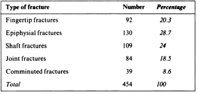
Figure 1.1: Classification of fractures of the phalanges (Barton, 1984)
Based on Figure 1.1, it shows that the classification phalanges fracture.
Although this statistic just cover fractures of the phalanges but for this
statistical it show that it need to design a new splint to change previous
treatment for hand and wrist fracture from using cast to another product that
easy to install.
Design for fracture hand and wrist need to present additive
manufacturing as reference to get a good result for heal support for frature hand
or wrist. This is due to the additive manufacturing can produce or develop
products to start producing very thin cross sections or simply called layer by
layer, one above another, until solid physical part completed. (Kenneth,
2002,p1). Other advantages that can be with additive manufacturing, because
it can be used in the manufacture of products based medicine, it is also able to
create form complex shapes that are nearly impossible to make using the
machine, and can build an internal structure, and even its ability to produce
features a very thin wall (Kenneth, 2002,p1).
Important thing that need to consider is an ergonomic and make a
product is ease to use and fitting. Based on Silverstein and Clark (2004),
Ergonomic will help a patient or human in two ways: by design an appropriate
task and equipment, it can avoid strainful body exertions and by using suitable
body structure. So, it is important to design a good splint to reduce stress for
hand and wrist and help patient to heal as soon as possible.
1.2
Introduction
According to Matthews (2012), the most common ailments that facing
athletes is injuries to the hand and wrist. This is an example of pain that
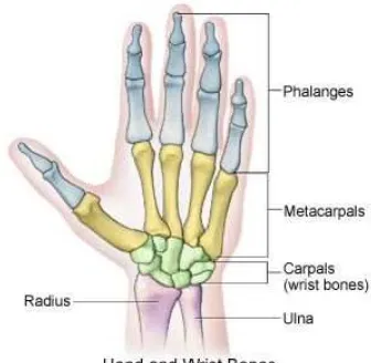
happend such as hand fracture. Hand have made up of bones called phalanges
and metacarpals. Bones of the fingers is called phalanges and bones that make
up your knuckles and connect to your wrist. Figure 1.2 show the example of
[image:21.595.251.419.437.601.2]hand and wrist bones.
Figure 1.2: Example of hand wrist bones
Hand are common injuries that affect specialist athletes and common
people when get involved with an accident. It can also be classified into two
main categories: traumatic (acute) and overuse (chronic) (Matthews,2012).
Traumatic usually occur for athletes that participate in footbll, hockey or
wrestling and for overuse usually occur for athletes that participate in baseball,
tennis or golf (Matthews ,2012).
The are two types of supporting device available in market to support
hand or wrist fracture cast and splint. Because of different ages and body sizes,
surface of the device not completely close to hand or wrist. When using cast,
cast need to cover with plastic back to prevent cast for an infection. Among
the important factors and should be considered is the material and ergonomic.
It is use in the production of the device because it is sufficient to give effect to
the hand and wrist as a supoort for the hand and as a device for healing.
So, to make supporting device, research must be focused on ergonomic
with an analysis using SolidWork to make Finite Element Analysis. With
questionaire, all customer requirement and needs will be identified to facilitate
the manufacture of the device.Additive manufacturing is one of technology that
used in all manufacturing process. It is easy for engineers to produce a good
prototype as well as to reduce the lead time of a product.
1.3
Problem statment
Currently, most of the supporting device for hand or wrist fracture made
from cast or splint. According to Bernett ( 2007) patient usually need to wear
cast or splint for a number of week. To reduce pain in hand and wrist, usually
it used cast or splint as one of the healing device. Material for cast are plaster
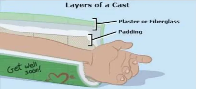
of paris or fiber class. When using a casts, it is too big because it used with two
layers of stiff bandages. The inside layer, which rests against the skin, is made
by soft cotton. The outer layer is hard to protect a broken bone from moving to
reduce injuries. Figure 1.3 shown layer of cast and it's usually made from one
[image:23.595.185.501.153.296.2]of two materials such as :
Figure 1.3: Layer of cast
(Source :< http://kidshealth.org/teen/safety/first_aid/casts.html> 29/09/13)
Plaster of Paris usually used for school art projects but in medical it
used to heal properly when patient keep broken or injured bones from moving.
A heavy white powder is mixed with water to form a thick paste that hardens
quickly. Plaster casts are heavier than fiberglass casts and can start to dissolve
if they get wet. It is difficult to patient to cure a plaster cast when take bath. If
the plaster get wet, the surface of plaster cast will delicate. The picture below
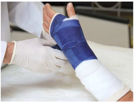
Figure 1.4: Example cast for broken hand using plastic of paris
(Source :< http://kidshealth.org/teen/safety/first_aid/casts.html> 29/09/13
Fiberglass is a type of moldable plastic available in many different
colors. Fiberglass casts are lighter and cooler than plaster casts. The outer layer
of a fiberglass cast is water resistant, but the inner layer is not, although it's
possible to get a waterproof liner for a fiberglass cast. Fiber glass is ease to
install and light however , it does not help when a patient have to take a bath.
There are a lot of device to support healing of fracture hand or wrist
hand but it is not convince because they are not water proof and difficult to
make a movement. when got fracture or injuries with hand or wrist, it not just
hand or wrist because the soft tissue around it is often injured as well. When a
cast or splint removed, hand or wrist need to get heal support for continues