UTEM BUS SYSTEM (UBS) USING ZIGBEE
MADIHAH BINTI DAUD
This report is submitted in partial fulfillment of the requirement for the Bachelor Degree in Electronic Engineering (Wireless Communication) with Honors
Faculty of Electronic and Computer Engineering University Technical Malaysia Melaka
UNIVERSTI TEKNIKAL MALAYSIA MELAKA
FAKULTI KEJURUTERAAN ELEKTRONIK DAN KEJURUTERAAN KOMPUTER
BORANG PENGESAHAN STATUS LAPORAN
PROJEK SARJANA MUDA II
Tajuk Projek :
Sesi
Pengajian :
Saya MADIHAH BINTI DAUD mengakumembenarkanLaporanProjekSarjana Muda ini disimpan di Perpustakaan dengan syarat-syarat kegunaan seperti berikut:
1. Laporan adalah hakmilik Universiti Teknikal Malaysia Melaka.
2. Perpustakaan dibenarkan membuat salinan untuk tujuan pengajian sahaja.
3. Perpustakaan dibenarkan membuat salinan laporan ini sebagai bahan pertukaran antara institusi pengajian tinggi.
4. Sila tandakan ( √ ) :
SULIT*
*(Mengandungi maklumat yang berdarjah keselamatan atau kepentingan Malaysia seperti yang termaktub di dalam AKTA RAHSIA RASMI 1972)
TERHAD** **(Mengandungi maklumat terhad yang telah ditentukan oleh
organisasi/badan di mana penyelidikan dijalankan)
TIDAK TERHAD
Disahkan oleh:
__________________________ ___________________________________
(TANDATANGAN PENULIS) (COP DAN TANDATANGAN PENYELIA)
Tarikh: ……….. Tarikh: ………..
UTEM BUS SYSTEM (UBS) USING ZIGBEE
“I hereby declare that this report is the result of my own work except for quotes as cited in the references.”
“I hereby declare that I have read through this report entitled “UTeM Bus System (UBS) using ZigBee” and found that it is enough in terms of scope and quality and has complied the partial fulfillment for the awarding of the Bachelor of Electronics
Engineering (Communication Wireless).”
Signature : ………..
Supervisor : ENGR. NOOR BADARIAH BTE ASAN
v
DEDICATION
vi
ACKNOWLEDGEMENT
Alhamdulillah, praise to Allah S.W.T for the guidance and blessing upon me, for without it I would not have been able to come this far.
I wish to give my appreciation to my respected supervisors Engr. Noor BadariahBintiAsan for their advice, understanding, good guidance and help throughout this project. Without their valuable suggestions and encouragement, this project would have not been successful.
vii
ABSTRACT
viii
ABSTRAK
ix
TABLE OF CONTENTS
CHAPTER CONTENT PAGE
PROJECT TITLE i
REPORT ACKNOWLEDGEMENT FORM ii
STUDENT DECLARATION FORM iii
SUPERVISOR DECLARATION PAGE iv
DEDICATION v
ACKNOWLEDGEMENT vi
ABSTRACK vii
TABLE OF CONTENT ix
LIST OF TABLE xii
LIST OF FIGURE xiii
LIST OF ABBREVIATIONS xv
1 INTRODUCTION
1.1 Overview of Project 1
1.2 Objective Project 2
1.3 Problem Statement 2
1.4 Scope of Project 3
1.5 Project Methodology 4
x
2 LITERATURE REVIEW
2.1 Chapter Overview 7
2.2 Previous Project 8
2.3 Software and Theory 13
2.4 Hardware and Theory 14
3 PROJECT METHODOLOGY
3.1 Review of Project Methodology 22
3.2 Introduction 23
3.3 Process of Project 24
3.4 Process of Flow Chart 25
3.5 Process of the System Flow Chart 27
3.6 Preparation of Printed Circuit Board 28
4 RESULT AND DISCUSSION
4.1 Introduction 32
4.2 Implementation 32
4.3 Simulation Result 34
4.4 Hardware Development 34
4.5 Software Development 37
4.6 Analysis Result 46
5 CONCLUSION AND RECOMMENDATION
5.1 Conclusion 48
xi
REFERENCES 50
APPENDIX A 52
APPENDIX B 56
xii
LIST OF TABLE
TABLE TITLE PAGE
2.1 Wireless Standard 20
2.2 Long Range Data Integrity 21
2.3 Low Power of X-Bee 21
xiii
LIST OF FIGURE
FIGURE TITLE PAGE
1.1 Scope of Project 3
1.2 UBS Block Diagram 4
2.1 RFID Reader and RFID Tag 9
2.2 ZigBee Network Topology 11
2.3 IC L7805 14
2.4 Power Supply Circuit 15
2.5 PIC16F877A 15
2.6 Microcontroller Circuit 16
2.7 Light Emitting Diode 17
2.8 LCD Display Circuit 18
2.9 X-Bee S2 19
3.1 Process of Project 26
3.2 Flow Chart of the System 27
3.3 Drilling Process 29
3.4 Soldering Process 30
3.5 Sucker Process 30
3.6 The Combination Circuit 31
4.1 Block Diagram of UBS 33
4.2 Prototype of UBS 33
4.3 Simulation the Power Supply Circuit 34
4.4 The Whole System 35
4.5 Circuit at Bus A and Bus B 36
xiv
4.7 Setup COM Port 39
4.8 Coordinator Test 40
4.9 Coordinator SH and SL 41
4.10 Coordinator Set the SH and SL 42
4.11 Router Set DH and DL 43
4.12 Router Terminal 44
4.13 Wireless Point to Point Communication 45
xv
LIST OF ABBREVIATIONS
UBS - UTeM Bus System
PIC - Peripheral Interface Controller LCD - Liquid-Crystal Display
GPS - Global Positioning System
SPICE - Simulation Program with Integrated Circuit Emphasis PCB - Printed Circuit Board
BASIC - Beginner's All-purpose Symbolic Instruction Code
RFID - Radio-Frequency Identification
LED - Light-Emitting Diode
GPRS - General Packet Radio Service
PC - Personal Computer
IEEE - Institute of Electrical and Electronic Engineers WSN - Wireless Sensor Network
WLAN- Wireless Local Area Network Tx - Transmitter
Rx - Receiver
IC - Integrated Circuit
V - Voltage
1
CHAPTER 1
INTRODUCTION
1.1 Overview of Project
2
proximity wireless transfer of data and the relatively low rate. ZigBee is intended to be easier and cheaper than other WPANs, such as Bluetooth [3].
The implementation of UTeM Bus Station (UBS) has nowadays has developed to incredible extent. This system is used to facilitate users. The aim of this study is to implement of UBS in UTeM campus bus. The main problem is that the campus buses are not consistent and not follow the schedule. This problem causing students will be late to class. In this research, a prototype of bus identification and monitoring system using Zigbee technology is to be developed. The objectives of this project are to design and develop UBS. It can detect a bus arrive at a distance of approximately 120 meters. It also makes it easier for users to preparebefore the bus arrive the destination.
1.2 Objective Project
The aim of this project is to design and develop UTeM Bus System (UBS) using ZigBee. In order to make this project successful, the objectives have been declared and must be achieved. The specific objectives of this project are:
i. To design and develop the prototype of the UTeM Bus System (UBS) using ZigBee.
ii. To implement the bus system more systematic.
1.3 Problem Statement
3
1.4 Scope of Project
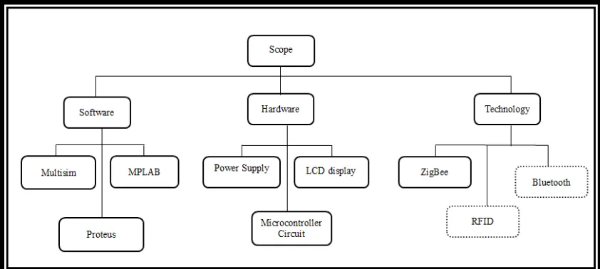
The scope of this project focuses into two parts in order to accomplish one complete system wireless networking, which is hardware and software. Figure 1.1 shows the scope of the project. For hardware parts it contains the circuit such as Microcontroller (PIC16F877A), Clock Oscillator, Power Supply, LCD display and Switch. The Microcontroller circuit PIC16F77A operate in 2.2V-5V, so the circuit is connected to a 5V power supply. PIC16F77A have Port A, Port B, Port C, Port D and Port E to use input and output. Then, the Clock Oscillator circuit it is important to give pulse to microcontroller circuit. LCD is in use is measuring 16x2. The purpose of the use is to display the bus destination to be reached and this makes it easier for students to know.
[image:18.595.151.572.486.675.2]The software part is also divided into parts, which are Multisim, Proteus and MPLAB. Multisim is to construct the circuit and to testing the circuit whether it functioning or not. The Proteus software is the circuit design and PCB making. This software usually used for circuit design and fabrication. The MPLAB is the programming language and environment was developing by Microsoft. It is to develop applications for Microchip microcontrollers and digital signal controller. Figure 1.1 shows the scope of the project.
4
1.5 Project Methodology
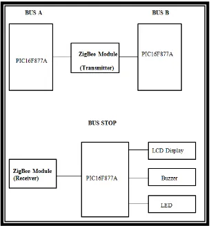
[image:19.595.167.473.286.614.2]This project focuses on wireless transmission data and the project development based on ZigBee technology. The Figure 1.2 shows the block diagram of UBS. The system will function properly when the ZigBee transmitter from the bus will send data to receiver at the bus stop will be detected at a wide ranged as far as 120 meters. The project methodology shows that the step will be taken to complete the project. Figure 1.2 shows the block diagram of UBS. This method covers the management, development design and project planning. Another method is used in this project is interview the users.
5
1.6 Report Structure
This report is covered by five chapters. The first Chapter starts with the background, introduction, problem statement, objective and the scope of work. The literature review is discussed in Chapter 2 and project methodology in Chapter 3. Chapter 4 covers software and hardware implementation and then the conclusions and suggestions are respectively covers in Chapter 5. For the projects that have been successfully implemented, there are some places to look into. Here are the main chapters:
Chapter 1: Study the objectives and scope of work project. Chapter 2: Literature review about wireless ZigBee system.
Chapter3: Project methodology covers the planning, design and management of development project.
Chapter 4: Software and Hardware and implementation. Chapter 5: Conclusion and suggestion on the project.
The project is divided into several chapters is to facilitate the project to run in a systematic way, and structured as the project can be implemented smoothly.
Chapter 1 is study about objectives and scope of work of the project.The aim of this project is to design and develop a wireless ZigBee system consists of UTeM Bus System.
Chapter 2 is about Literature review for wireless ZigBee system and PIC.Research, find and read relevant topics from the sources such as journal, conference paper, reference book and internet let‟s get deeper knowledge and information for the project. Research on the same system or even less in the market and know what are the characteristics and capabilities of the product will also provide more information and understanding in this project.
Chapter 3 is about project methodology covers the planning, design and management of development projects.This chapter explains more about the project methodology used in this project. This section will explain more about the way it projects from start to finish. Every single thing has been implemented in the project should be describes step by step.
6
shows the testing process. Testing will be performed on each module in both software and hardware systems.
7
CHAPTER 2
LITERATURE REVIEW
2.1 Chapter Overview
8
specified in this project and the components used in the project is determined. Therefore, it is functional and well understood concept.
2.2 Previous Projects
2.2.1 Title: UKM Campus Bus Identification and Monitoring Using RFID and GIS by AishahMahani Mustapha, MA Hannan, Aini Hussain and Hassan Basri, [2009] [3].
This paper discuss about the implementation of Intelligent Transportation System (ITS) nowadays has developed to incredible extent. This system is proved to be very useful not only in sense of the safety of the vehicles, but ease the users. This paper research the aim of this study is the implementation of ITS in UKM campus bus. The main problem is that the campus buses are not consistent and do not follow the schedule. It is causing the students to be late to class. Also, in this research a prototype of bus identification and monitoring system using Radio-frequency Identification (RFID) and Geographical Information System (GIS) is to be developed. RFID is the technique used to monitor and identify the location of a certain bus, presented in the form of map aided by GIS software. The tag and the reader of the RFID devices are wirelessly connected. The signal sent out by the tag sent out by the tag will be read by the reader when the both the devices are in the fixed proximity. The read signal is then sent for data utilization.
9
[image:24.595.179.496.195.331.2]signal. The operational principle of RFID systems such that when the readers enter the reader work field of RFID label, they will send out radio frequency signals through the antenna; inducing current powers that enable the tag to send out encoded message. The message sent is then received by the readers and interpreted by a system connected to them.
Figure 2.1: RFID Reader and RFID Tag
2.2.2 Tittle: Bus Management System Using RFID in WSN by Ben AmmarHatem and Hamam Habib, [2009] [2].
This paper discuss about to integrated RFID (Radio Frequency IDentification) in WSN (Wireless Sensor Network). WSN is used to support RFID identification process by extending the read range of an RFID system. The WSN can monitor the environment of an object and optimize RFID reader‟s performance and energy. Then, methodology to integrate RFID technology, wireless sensor network to form an intelligent bus tracking application is studied. The proposed system can monitor bus traffic inside spacious bus stations, and can inform administrators whether the bus is arriving on time, early or late. This information is then displayed on the different wireless displays inside and outside the bus station. New technology can help the administrator to monitor the buses traffic while increasing the satisfaction of transit users and reducing cost through efficient operations asset utilization. Well-known examples of identification technologies include Closed-Circuit Television (CCTV) and Global Positioning System (GPS).