VIBRATION CONTROL OF A COUPLED CYLINDER UNDER ROTATIONAL MOTION
JOSUA TAINSING B041110233
BMCL
Email: [email protected]
Draft Final Report Projek Sarjana Muda II
Supervisor: DR. ROSZAIDI RAMLAN
Faculty of Mechanical Engineering Universiti Teknikal Malaysia Melaka
SUPERVISOR DECLARATION
“I hereby declare that I have read this thesis and in my opinion this report is sufficient in terms of scope and quality for the award of the degree of
Bachelor of Mechanical Engineering (Plant & Maintenance)”
i
VIBRATION CONTROL OF A COUPLED CYLINDER UNDER ROTATIONAL MOTION
JOSUA TAINSING
This Report Is Submitted In Partial Fulfilment of Requirement For Degree of Bachelor of Mechanical Enginering (Plant & Maintenance)
Faculty of Mechanical Engineering Universiti Teknikal Malaysia Melaka
DECLARATION
“I hereby declare that the work in this report is my own except for summaries and quotations which have been dully acknowledge”
iii
I dedicate my final year project to my family and my supervisor Dr. Roszaidi Ramlan. A
special feeling of gratitude to my loving parents, Tainsing Somundoh and Lotimah Sogiloi
whose encouragement and supported me throughout my degree. I will always appreciate all
ACKNOWLEDGEMENT
v
ABSTRACT
ABSTRAK
vii
TABLE OF CONTENTS
CHAPTER TITLE PAGE
PROJECT TITLE DECLARATION DEDICATION ACKNOWLEDGEMENT ABSTRACT ABSTRAK
TABLE OF CONTENTS LIST OF TABLES LIST OF FIGURES LIST OF SYMBOLS
LIST OF ABBREVIATIONS
i ii iii iv v vi vii xi xii xvi xviii
CHAPTER I INTRODUCTION
1.1 Problem Statement 1.2 Objective
1.3 Scope
1 1 2 2
CHAPTER II LITERATURE REVIEW
2.1 Fundamental of Vibration
2.2 Classification, Terminologies and
Quantification of Vibration 2.3 Vibration Analysis
2.3.1 Vibration Analysis Procedure 2.3.2 Vibration Sensors
2.4 Vibration of a Coupled Cylinder Under Rotation Motion
2.4.1 Torsional Vibration 2.4.2 Lateral Vibration
2.4.4 Eccentricity 2.5 Coupling
18 20
CHAPTER III METHODOLOGY
3.1 Analytical Study 3.2 Device Planning 3.3 Device Fabrication 3.4 Apparatus Preparation 3.5 Experimental Study
3.6 Collecting Data and Analysis
23 25 27 28 30 31 33
CHAPTER IV THEORETICAL ANALYSIS
4.1 Rotational Vibration 4.2 Radial Vibration
4.3 Fast Fourier Transform (FFT)
34 34 36 39
CHAPTER V DATA AND RESULT
5.1 Baseline Measurement 5.1.1 Motor Uncoupled 5.1.2 Rigid Shaft
5.2 Effect of Load and Rotational Speed to
Vibration Characteristic of Rotating Shaft 5.3 Effect of Shaft’s Length to Vibration
Characteristic of Rotating Shaft 5.4 Effect of Unbalance to Vibration Characteristic of Rotating Shaft 5.5 Effect of Misalignment to Vibration Characteristic of Rotating Shaft
5.6 Effect of Different Coupling to Vibration Characteristic of Coupled Rotating Shaft Under Different Condition
5.6.1 Effect of Different Coupling to
Vibration Characteristic of Coupled
ix
Rotating Shaft With and Without Load
5.6.2 Effect of Different Coupling at Different Location to Vibration Characteristic of Coupled Rotating Shaft
5.6.3 Effect of Different Coupling to Vibration Characteristic of Coupled Rotating Shaft Under Eccentric Load 5.6.4 Effect of Different Coupling to Vibration Characteristic of Coupled Rotating Shaft Under Misalignment
69
73
77
80
CHAPTER VI ANALYSIS AND DISCUSSION
6.1 Baseline Measurement 6.1.1 Motor Uncoupled 6.1.2 Rigid Shaft
6.2 Effect of Load and Rotational Speed to
Vibration Characteristic of Rotating Shaft 6.3 Effect of Shaft’s Length to Vibration
Characteristic of Rotating Shaft 6.4 Effect of Unbalance to Vibration Characteristic of Rotating Shaft 6.5 Effect of Misalignment to Vibration Characteristic of Rotating Shaft
6.6 Effect of Different Coupling to Vibration Characteristic of Coupled Rotating Shaft Under Different Condition
6.6.1 Effect of Different Coupling to
Vibration Characteristic of Coupled Rotating Shaft With and Without Load
6.6.2 Effect of Different Coupling at
Characteristic of Coupled Rotating Shaft
6.6.3 Effect of Different Coupling to Vibration Characteristic of Coupled Rotating Shaft Under Eccentric Load 6.6.4 Effect of Different Coupling to Vibration Characteristic of Coupled Rotating Shaft Under Misalignment
90
91
91
CHAPTER IV CONCLUSION AND RECOMMENDATION
7.1 Conclusion 7.2 Recommendation
93 93 96
xi
LIST OF TABLES
NO TITLE PAGE
2.1 Factors of Vibration for Each Mode 10 2.2 Effects of Vibration for Each Mode 11
3.1 Gantt Chart 25
LIST OF FIGURES
NO TITLE PAGE
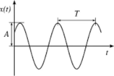
2.01 Amplitude and Period of Sinusoidal Wave 4 2.02 Average, RMS and Peak of Sinusoidal Wave 5 2.03 Sensitivity of Sensors Over Different Frequency Range 8
2.04 Type of Drillstring Vibration 10
2.05 Mechanical Modeling of Torsional Vibration 13
2.06 Type of Whirl 14
2.07 Mechanical Modeling of Lateral Vibration 15 2.08 Parallel Misalignment Frequency Spectrum 16 2.09 Angular Misalignment Frequency Spectrum 17
2.10 Unbalance Frequency Spectrum 18
2.11 Two Types of Eccentricity 19
3.01 Flow Chart of Project 24
3.02 Flow Chart of Analytical Study 26
3.03 Disc Coupling 27
3.04 Jaw Coupling 27
3.05 Rubber Coupling 27
3.06 Apparatus Arrangement 28
3.07 Test Rig 29
3.08 Point of Measurement and Its sensor 30
3.09 Flow Chart of Experimental Study 31
3.10 Flow Chart of Data Collection and Analysis 33 4.01 Mechanical Modelling of Rotational Vibration 34 4.02 Displacement Transmissibility From Pipe 1 to Pipe 2 36 4.03 Mechanical Modelling of Lateral Vibration 37
4.04 Frequency Response Function 39
xiii
4.06 Unbalance Frequency Spectrum 40
4.07 Parallel Misalignment Frequency Spectrum (Radial Direction) 40 4.08 Parallel Misalignment Frequency Spectrum (Axial Direction) 41 4.09 Angular Misalignment Frequency Spectrum (Axial Direction) 41 4.10 Angular Misalignment Frequency Spectrum (Radial Direction) 42 5.01 Condition of Baseline Measurement 44 5.02 Graph of Velocity Against Order – Motor Horizontal 45 5.03 Graph of Velocity Against Order – Motor Vertical 45 5.04 Graph of Velocity against Order – Motor Axial 46
5.05 Condition of Rigid Shaft Testing 47
5.06 Graph of Velocity against Order – Inboard Horizontal 48 5.07 Graph of Velocity against Order – Inboard Vertical 48 5.08 Graph of Velocity against Order – Inboard Axial 49 5.09 Graph of Velocity against Order – Outboard Horizontal 49 5.10 Graph of Velocity against Order – Outboard Vertical 50 5.11 Graph of Velocity against Order – Outboard Axial 50
5.12 Loaded Shaft 51
5.13 Graph of Velocity against Order – Inboard Horizontal 52 5.14 Graph of Velocity against Order – Inboard Vertical 52 5.15 Graph of Velocity against Order – Inboard Axial 53 5.16 Graph of Velocity against Order – Outboard Horizontal 53 5.17 Graph of Velocity against Order – Outboard Vertical 54 5.18 Graph of Velocity against Order – Outboard Axial 54 5.19 Coupling Located at ½ L from Inboard 55 5.20 Coupling Located at ¼ L from Inboard 56 5.21 Coupling Located at ¾ L from Inboard 56 5.22 Graph of Velocity against Order – Inboard Horizontal 57 5.23 Graph of Velocity against Order – Inboard Vertical 57 5.24 Graph of Velocity against Order – Inboard Axial 58 5.25 Graph of Velocity against Order – Outboard Horizontal 58 5.26 Graph of Velocity against Order – Outboard Vertical 59 5.27 Graph of Velocity against Order – Outboard Axial 59
5.30 Graph of Velocity against Order – Inboard Vertical 61 5.31 Graph of Velocity against Order – Inboard Axial 62 5.32 Graph of Velocity against Order – Outboard Horizontal 62 5.33 Graph of Velocity against Order – Outboard Vertical 63 5.34 Graph of Velocity against Order – Outboard Axial 63 5.35 Position of Inboard(left) and Outboard(right) for Misalignment
Test
64
5.36 Graph of Velocity against Order – Inboard Horizontal 65 5.37 Graph of Velocity against Order – Inboard Vertical 65 5.38 Graph of Velocity against Order – Inboard Axial 66 5.39 Graph of Velocity against Order – Outboard Horizontal 66 5.40 Graph of Velocity against Order – Outboard Vertical 67 5.41 Graph of Velocity against Order – Outboard Axial 67
5.42 Different Type of Coupling 67
xv
5.61 Graph of Velocity against Order – Inboard Axial 79 5.62 Position of Inboard(left) and Outboard(right) for Misalignment
Test 80
LIST OF SYMBOLS
= Frequency = Period = Time
= Displacement along -axis = Displacement along -axis = Amplitude
= Phase
= Angular frequency = Exponential = Imaginary
= Inertial mass of rotary = Inertial mass of bit = Inertial mass of pipe 1 = Inertial mass of pipe 2 = Radius
= Transmissibility = Torque on motor = Torque on bit = Torque on rotary = Angular displacement = Angular velocity = Angular acceleration
= Mass = Damping = Stiffness = Damping ratio
xvii
= Ratio of angular frequency to natural angular frequency = Fluid force
= Force on bit
= Force on direction = Force on direction = Normal force = Tangential force
LIST OF ABBREVIATIONS
RMS - Root mean square BHA - Bottom hole assembly ROP - Rate of penetration
1
CHAPTER I
INTRODUCTION
This research is about the study of vibration control of a coupled cylinder under rotational motion as faced in oil drilling process. Oil drilling process is prone to many types of vibration problem. This research will lead to the understanding of the vibration problem and how to control them.
1.1 Problem Statement
The line of drill pipes in oil drilling process is subjected to three modes of vibration which are axial, radial and torsional. The real situation in oil drilling process was imitated in laboratory, where the rotary table, drill pipe, connection and drilling mud is characterised as the motor, cylinder or shaft, coupling and load respectively.
Axial vibrations, is a motion along the lengthwise axis of the cylinder. In drilling process, this is mostly due to the interaction between drilling bit and the hole bottom. This vibration is called ‘‘bitbounce’’. Axial vibration was introduced by introducing angular misalignment as this type of misalignment tends to create a strong vibration in axial direction.
mass will generate centrifugal force which is in radial or lateral direction.
Torsional or rotational vibrations caused by nonlinear load magnitude. The rotational vibration of the cylinder characterized by alternating stops during which the pipe sticks and intervals of large angular velocity of the pipe. However, due to equipment availability restriction in the laboratory, only analytical analysis was conducted for this type of vibration.
Different physical parameters of the oil drilling equipment were also studied. That includes the effect of different parameters in a coupled cylinder which include load, rotational speed, cylinder’s length, and different type of coupling.
1.2 Scope
The problem imitates the real problem during oil drilling process. Involve theoretical mechanical modelling of the dynamics of the coupled cylinders. A test will be fabricated and tested. The study will lead to understanding of what governs the good vibration control properties of the coupled structure. The study will also gain knowledge on how to control the vibration.
1.3 Objective
1. To study the vibration characteristics of a coupled cylinder.
2. To study the effect of coupling mechanism and how to control the vibration at the coupling.
3
CHAPTER II
LITERATURE REVIEW
In this chapter, all of information related to vibration analysis and control that used for the study of vibration characteristic of coupled cylinder under rotational motion was elaborated. Literature review is important process to get all information related to this research.
2.1 Fundamental of Vibration
According to Putra (2013a), Vibration is the motion of a particle or a body from a position of equilibrium. Vibration occurs when a system is moved from equilibrium position. The system will return to equilibrium position under the action of restoring forces such as the elastic forces, as for a mass attached to a spring, or gravitational forces, as for a simple pendulum. The system keeps moving back and forth across the equilibrium position.
Most vibrations are undesirable in machines and structures because they produce increased stresses, energy losses, causes added wear, increase bearing loads, induce fatigue, create passenger discomfort in vehicles, and absorb energy from the system. Vibration causes noise which creates discomfort and annoyance to human. In some field, vibration is found to be beneficial such as in tooth cleaning, massage chair, music instrument and energy harvesting.
prevent damage from vibrations.
2.2 Classification, Terminologies and Quantification of Vibration
Vibrations can be classified into three categories which are free, forced, and self-excited. Free vibration occurs with the absence of external force in the system. An external force that acts on the system causes forced vibrations. In this case, the exciting force continuously supplies energy to the system. Self-excited vibrations are periodic and deterministic oscillations. In contrast to forced vibrations, the exciting force is independent of the vibrations and can still persist even when the system is prevented from vibrating.
Below are some basic terminologies in vibration (Putra 2013b): Mass - store of kinetic energy
Stiffness - store of potential (strain) energy Damping - dissipate energy
Force - provide energy
Amplitude - level of vibration from the equilibrium position (displacement, velocity, acceleration)
Frequency - Frequency is the number of cycles repeated per second. The unit is Hertz (Hz)
[image:24.595.226.413.598.723.2] Phase - Angle difference between a measured point and a reference point Quantification of vibration: