DESIGN AND ANALYSIS OF A MOBILE ROBOT
MECHANISM FOR MAINTENANCE WORKS IN
MANUFACTURING ENVIRONMENT
LIM SAY LI
B051110249
UNIVERSITI TEKNIKAL MALAYSIA MELAKA
UNIVERSITI TEKNIKAL MALAYSIA MELAKA
DESIGN AND ANALYSIS OF A MOBILE ROBOT MECHANISM
FOR MAINTENANCE WORKS IN MANUFACTURING
ENVIRONMENT
This report submitted in accordance with requirement of the Universiti Teknikal
Malaysia Melaka (UTeM) for the Bachelor Degree of Manufacturing Engineering
(Robotics & Automation) (Hons.)
by
LIM SAY LI B051110249 911116-14-6528
FACULTY OF MANUFACTURING ENGINEERING
UNIVERSITI TEKNIKAL MALAYSIA MELAKA
BORANG PENGESAHAN STATUS LAPORAN PROJEK SARJANA MUDA
TAJUK: Design and Analysis of a Mobile Robot Mechanism for Maintenance
Works in Manufacturing Environment.
SESI PENGAJIAN: 2014/15 Semester 2
Saya LIM SAY LI
mengaku membenarkan Laporan PSM ini disimpan di Perpustakaan Universiti Teknikal Malaysia Melaka (UTeM) dengan syarat-syarat kegunaan seperti berikut:
1. Laporan PSM adalah hak milik Universiti Teknikal Malaysia Melaka dan penulis. 2. Perpustakaan Universiti Teknikal Malaysia Melaka dibenarkan membuat salinan
untuk tujuan pengajian sahaja dengan izin penulis.
3. Perpustakaan dibenarkan membuat salinan laporan PSM ini sebagai bahan pertukaran antara institusi pengajian tinggi.
4. **Sila tandakan ( )
SULIT
TERHAD
TIDAK TERHAD
(Mengandungi maklumat yang berdarjah keselamatan atau kepentingan Malaysia sebagaimana yang termaktub dalam AKTA RAHSIA RASMI 1972)
(Mengandungi maklumat TERHAD yang telah ditentukan oleh organisasi/badan di mana penyelidikan dijalankan)
Alamat Tetap:
DECLARATION
I hereby, declared this report entitled “Design and Analysis of a Mobile Robot
Mechanism for Maintenance Works in Manufacturing Environment” is the
results of my own research except as cited in references.
Signature : ……….
Author’s Name : ……….
APPROVAL
This report is submitted to the Faculty of Manufacturing Engineering of UTeM
as a partial fulfilment of the requirements for the degree of Bachelor of
Manufacturing Engineering (Robotics & Automation) (Hons.). The member of
the supervisory is as follow:
ABSTRAK
Laporan ini membentangkan reka bentuk dan analisis mekanisme robot mudah
alih untuk kerja-kerja penyelenggaraan dalam persekitaran pembuatan. Robot
mudah alih yang dicadangkan untuk melaksanakan penyelenggaraan ke atas mesin
larik MOMAC SM 200. Ia sepatutnya membersihkan cecair penyejuk selepas
operasi mesin untuk mengelakkan apa-apa kerosakan yang berpotensi untuk
mesin. Mekanisme robot mudah alih terdiri daripada tiga bahagian asas iaitu
platform mudah alih untuk pergerakan, lengan manipulator untuk manipulasi, dan
akhir-efektor pelaksanaan tugas. Untuk menentukan prestasi yang terbaik untuk
pelaksanaan tugas, dua reka bentuk telah dihasilkan dengan menggunakan perisian
SolidWorks 2014 berdasarkan keperluan yang dikenal pasti. Reka bentuk
dianalisis dengan perisian SolidWorks Simulasi dengan membangunkan prototaip
maya dalam ruang kerja maya. Simulasi yang digunakan untuk melakukan dua
analisis yang Analisis Usul dan Analisis Unsur Terhingga (FEA). Dalam analisis
pergerakan, pergerakan robot mudah alih bagi setiap kitaran, dimana satu set ke
depan dan balik akan dianggap sebagai satu kitaran dan dianalisis. Masa yang
diambil olehnya untuk melaksanakan pergerakkan itu diambil sebagai pengukuran
prestasi. Di FEA, tegasan dan terikan di bawah beban dalaman dan luaran akan
dikira. Kedua-dua robot mudah alih akan dinilai berdasarkan data yang
dikumpulkan. Bagi prospek pembangunan projek ini pada masa depan,
aspek-aspek berikut seperti halangan mengelakkan untuk mengelakkan robot mudah alih
daripada berlanggar dengan mesin, kaedah navigasi untuk robot mudah alih untuk
bergerak dari kedudukan asal ke kedudukan akhir dan pelaksanaan sensor untuk
mengaktifkan prestasi robot mudah alih dicadangkan untuk dilaksanakan.
ABSTRACT
This report presents the design and analysis of a mobile robot mechanism for
maintenance works in manufacturing environment. The mobile robot is proposed
to perform maintenance on MOMAC SM 200 lathe machine. It supposed to clean
up the coolant fluid after the machine’s operation to prevent any potential damage
to the machine. The mobile robot mechanism composed of three basic parts which
are mobile platform for locomotion, manipulator arm for manipulation, and
end-effector task execution. In order to determine the best performance for task
execution, two designs are produced by using SolidWorks 2014 software based on
the requirements identified. The designs are analyzed with SolidWorks Simulation
software by developing a virtual prototype in a virtual workspace. The simulation
is used to perform two analysis which are Motion Analysis and Finite Element
Analysis (FEA). In motion analysis, the motion of mobile robot per cycle, where
one set of back and forth of the mobile robot’s manipulator is considered as one
cycle, is analyzed. The time taken for it to perform the motion is taken as a
measurement of the performance. Where in FEA, the stresses and strains under
internal and external loads is determined. The mobile robot’s performance is
evaluated based on the result collected. For future prospect of this project
development, the following aspects such as obstacles avoidance to prevent the
mobile robot from colliding with the machine, navigation method for the mobile
robot to move from original position to final position and implementation of
sensor to activate the mobile robot’s performance is suggested to be undertaken.
DEDICATION
This project is dedicated to my beloved father, Lim Poh Chye, and both of my
supportive brothers, Lim Kok Tiong and Lim Kok Yew. Thanks for their
continuously support during my study process.
ACKNOWLEDGEMENT
I would like to express my deepest gratitude to all those who helped me in
completing this Final Year Project (FYP). The special thanks goes to my project
supervisor, Dr. Fairul Azni bin Jafar who guided me throughout the process of
completing this project. I would like to express my appreciation towards his ideas,
guidance, encouragement, and supervision in ensuring the progress of this project
run smoothly as scheduled. Not to forget the guidance provided by all the lecturers
who gave useful advices and comment to me, it is much appreciated. My grateful
thanks are extended to all my friends for their bright ideas and firm support. Last
but not least, I would like to thanks my family member for their continuously
support and enthusiastic encouragement throughout my study.
TABLE OF CONTENT
List of Abbreviations, Symbols and Nomenclatures xi
CHAPTER 1: INTRODUCTION 1
2.3.1 Importance of Maintenance in Manufacturing 11
2.4 Mobile Robot for Maintenance 11
2.4.1 Applications of Mobile Robot for Maintenance 12
2.4.1.1 Nuclear Industry 12
2.4.1.2 Highways 13
2.4.1.3 Railways 13
2.4.1.4 Power Line Maintenance 13
2.4.1.5 Aircraft Servicing 14
2.4.1.6 Underwater Facilities 14
2.4.1.7 Coke Ovens 14
2.4.2 Advantages of Mobile Robot for Maintenance 14
2.4.3 Mobile Robot for Maintenance in Manufacturing Environment 15
2.5 Summary 15
3.4.2 Identify Requirements 23
3.4.3 Establish Concept 23
3.5 Mobile Robot Design 23
3.5.1 Concepts Generation 24
3.5.2 Concept Development 26
3.6 Analysis 26
3.6.1 Software Selection 27
3.6.2 Experimental Setup 28
3.6.3 Experimental Procedures 28
3.6.4 Data Collection 29
3.6.5 Data Analysis 29
3.7 Expected Result 29
3.7 Summary 29
CHAPTER 4: DESIGN DEVELOPMENT 31
4.1 Concept Generation 31
4.1.1 MOMAC SM 200 Conventional Lathe Machine 32
4.2 Concept Development 35
4.2.1 Parts and Components 35
4.2.1.1 Mobile Robot Platform 36
4.2.1.2 Manipulator Arm 41
4.2.1.3 End-effector 43
4.2.2 Assembly 46
4.2.2.1 Designs of Mobile Robot Mechanism 46
4.3 Design tools 50
4.4 Summary 50
CHAPTER 5: ANALYSIS 52
5.1 Software Selection 52
5.2 Motion Analysis 52
5.2.1 Experiment 1 53
5.2.1.1 Movement 1 53
5.2.1.2 Movement 2 56
5.2.1.3 Discussion for Experiment 1 60
5.2.2 Experiment 2 61
5.2.2.1 Results 61
5.2.2.2 Discussion for Experiment 2 64
5.3 Finite Element Analysis 64
5.3.1 One tool attached 65
5.3.2 Two tools attached 69
5.3.3 Discussion for FEA 71
5.4 Summary 71
CHAPTER 6: CONCLUSION & FUTURE WORK 72
6.1 Conclusion 72
6.2 Suggestions for Future Work 73
REFERENCES 74
LIST OF TABLES
3.1 Project Gantt chart for FYP 1 17
3.2 Project Gantt chart for FYP 2 18
4.1 Dimension of parts of MOMAC SM 200 Conventional Lathe Machine 34
4.2 Dimension of mobile robot platform 38
4.3 Dimension of wheel mechanism 39
4.4 Details of Tool A and Tool B 44
5.1 Parameters for Experiment 1 (Movement 1) 53
5.2 Parameters for Experiment 1 (Movement 2) 57
5.3 Summary of the result in Experiment 1 60
5.4 Summary of the result in Experiment 2 64
5.5 Material Properties of one tool mobile robot 65
5.6 Loads and fixtures of one tool mobile robot 67
5.7 Loads and fixtures of two tools mobile robot 69
LIST OF FIGURES
2.1 PackBot is one of the example of UGV 6
2.2 Camclone T21 UAV is developed for the usage of Smart Skies Project 6
2.3 Picture of ALTEX AUV being launched in Arctic seas 7
2.4 Nao is one of the example of human-like robot 7
2.5 AIBO is a dog-like robot 8
2.6 DuctCleaner Robot uses wheels to move around 8
2.7 Nanokhod uses tracks to perform its locomotion 8
3.1 Overall methodology 19
3.2 Flowchart of literature review process 20
3.3 Flowchart of project planning process 22
3.4 Flowchart of mobile robot design process 24
3.5 Parts that combined to form a desired mobile robot 25
3.6 Multiview of the basic ideas 25
3.7 3-D view of the mobile robot 26
3.8 Flowchart of analysis process 27
3.9 Simulation software available 27
4.1 MOMAC SM 200 Conventional Lathe Machine in FKP 32
4.2 Illustration for Part A and B 33
4.3 Illustration for part C, D, E, F and G 34
4.4 Mobile robot platform 36
4.5 Multiview of mobile robot platform 37
4.6 Wheel mounted with wheel case 39
4.7 Multiview of wheel mechanism 40
4.8 Manipulator arm 41
4.9 Multiview of manipulator arm 42
4.10 Tool A 43
4.11 Tool B 44
4.12 Multiview of Tool A 45
4.13 Multiview of Tool B 45
5.3 Linear Displacement VS Time Graph of Design A for Movement 1 55
5.4 Linear Displacement VS Time Graph of Design B for Movement 1 56
5.5 Track path of Design A for Movement 2 57
5.6 Track path of Design B for Movement 2 57
5.7 Linear Displacement VS Time Graph of Design A for Movement 2 59
5.8 Linear Displacement VS Time Graph of Design B for Movement 2 60
5.9 Track path produced by different number of tools attached 61
5.10 Linear Velocity VS Time Graph for one tool attached 62
5.11 Linear Velocity VS Time Graph for two tools attached 63
5.12 Linear Velocity VS Time Graph for four tools attached 63
5.13 Stress plot of with one tool 68
5.14 Strain plot of with one tool 68
5.15 Stress plot of with two tools 70
5.16 Strain plot of with two tools 70
LIST OF ABBREVIATIONS, SYMBOLS AND
NOMENCLATURE
UTeM - Universiti Teknikal Malaysia Melaka
FKP - Faculty of Manufacturing Engineering
FYP - Final Year Project
FEA - Finite Element Analysis
UGVs - Unmanned Ground Vehicles
UAVs - Unmanned Aerial Vehicles
AUVs - Autonomous Underwater Vehicles
CAD - Computer Aided Design
VS - Versus
The brief information of this project “Design and Analysis of a Mobile Robot
Mechanism for Maintenance Works in Manufacturing Environment.” is presented in
this chapter.
1.1 Background
Industrial robotics plays an important role in manufacturing industries. However, the
industrial robots of today are mainly lack in flexibility and are attached in a fixed
location. Therefore, mobile robots that are capable of moving around are introduced
in manufacturing environment to overcome the limitations in fixed industrial robots.
Unlike typical industrial robots, mobile robots with manipulator are not fixed in
certain position. Hence, it is possible for the mobile robots to be used in different
surrounding and perform various tasks (Dang et al., 2013).
The usage of mobile robots in manufacturing maintenance is still new due to the
condition of most maintenance tasks requires great manipulation skills and
experiences. But this does not means that mobile robot cannot be used for
maintenance purposes. Mobile robots are preferable than human workers in certain
cases such as task execution in human inaccessible areas (eg. the backside of
manufacturing equipment). Besides, using robots instead of human workers in
workplace that might be hazardous is better to prevent in putting human life at risk
(Ghazali et al., 2012).
INTRODUCTION
CHAPTER 1
1.2 Motivation
To achieve superior job satisfaction, robots are working together with labour, to
undertake the unsafe, exhausting or certain irritating duties and act as a free labour
that is able to work in more creative or adaptive manner (Colestock, 2005).
Environment with relatively low human accessibility encourages the usage of mobile
robots for maintenance and repair (Parker & Draper, 1998). Human workers have
higher flexibility but less reliability in performing tasks consistently. While robot are
relatively less flexible because it is programed to do task with high reliability. There
are less mobile robot are seen to use for maintenance in manufacturing field.
Therefore, it motivates to construct a project in designing mobile robot for
maintenance with consistent performance and good reliability.
1.3 Problem Statement
In manufacturing industry, lathe machine is used to perform turning operation on
cylindrical product that made of metal. During the turning process, coolant is
dispersed to prevent the machine from overheating. However, the coolant often
contaminates the machine body parts and requires to be cleaned up to prevent
potential damage to the machine. This task always done by human after the machine
operation is finished. It seems like a simple task to a human but it could be dangerous
when the machine malfunction. Thus, it promotes to design a mobile robot to
perform this maintenance tasks in this project.
1.4 Objectives
The objectives of this project are:
(a) To design a mobile robot mechanism for maintenance works.
(b) To analyse the performance of the proposed maintenance robot.
1.5 Scope
The purpose of this project is to design a robot that is able to perform maintenance
tasks in manufacturing environment. The robot is to be built in mobile state instead
of static state. The maintenance tasks that can be done by the mobile robot is strictly
limited in manufacturing environment. Maintenance task that focused in this project
is to mechanically clean up the fluid.
Furthermore, this project is focusing on designing the proposed robot system before
being simulated by a chosen software in order to clarify the performance. The
performance index will be evaluated in term of motion performance as well as the
ability to perform the maintenance tasks. Obstacle avoidance and navigation methods
of the mobile robot are not covered in this project due to time constraint. In addition,
the research done in this project is merely fundamental studies in maintenance
mobile robot field.
1.6 Report Structure
In Chapter 1, a short introduction regarding on the project is shown. The introduction
includes the project background, motivation behind this project, problem statement,
objectives, scope of the project and lastly the report structure.
In Chapter 2, the literature review on maintenance mobile robot is written. Related
information regarding on the topics are discussed. For example, mobile robot,
maintenance work and application of mobile robot in maintenance.
In Chapter 3, methodology involved in this project is illustrated with the aid of flow
chart. The methodologies involved are literature review, project planning, mobile
robot design, and analysis.
In Chapter 4, the design development of the mobile robot is shown. The concept
generation and concept development process are included. In addition, the design
tools in developing the drawing is described as well.
In Chapter 5, the analysis that carried out for this project is elaborated. The
experiments to be carried out is described in details. The data of the analysis result is
discussed.
In Chapter 6, conclusion of this project are made. The most suitable design is opted
based on the result of the analysis concluded. Furthermore, suggestion for future
work is discussed to improve this project.
This chapter illustrates the basic idea in designing a mobile robot mechanism for
maintenance with reference to existing mobile robots application. This project
focused on design and analysis of a mobile robot mechanism specifically to
perform maintenance tasks in manufacturing industry.
2.1 Mobile Robot
Robotics has attained its greatest success as yet in the field of industrial
manufacturing. However, the robots in the industrial field still lacking behind for its
mobility. A fixed robot arm is limited by where it is bolted causing the range of
motion is restricted. In contrast, mobile robot have the ability to move around
throughout the manufacturing plant and is not fixed in one physical location
(Siegwart & Nourbakhsh, 2004). The limitations of industrial robots that are either
stationary or fixed in certain places had promoted the usage of mobile robot. The use
of mobile robot has been awhile. Formerly, people have been controlling mobile
robots by using large, heavy and expensive computer systems that were difficult to
carry and need to be connected via cable or wireless devices. Nowadays, however,
mobile robots can be controlled by using cheaper, smaller and lighter embedded
computer systems that are carried on-board the robot (Braunl, 2006).
LITERATURE REVIEW
CHAPTER 2
2.1.1 Classifications of Mobile Robot
Mobile robots can be classified according to the environment travelled. The
classifications are as below:
(a) Unmanned Ground Vehicles (UGVs) which are the land or home robots,
(b) Unmanned Aerial Vehicles (UAVs) which are the aerial robots,
(c) Autonomous Underwater Vehicles (AUVs) which are the underwater robots,
(d) Polar robots.
Figure 2.1: PackBot is one of the example of UGV (Source:
<http://www.irobot.com/For-Defense-and-Security/Robots/510-PackBot.aspx#PublicSafety> 28/11/14).
Figure 2.3: Picture of ALTEX AUV being launched in Arctic seas (MBARI, 2002).
Mobile robots can also be classified according to the method used to move. The
classifications are as below:
(a) Human-like or animal-like legged robot,
(b) Wheeled robot, and
(c) Tracks.
Figure 2.4: Nao is one of the example of human-like robot (Source:
<http://www.aldebaran.com/en/humanoid-robot/nao-robot> 28/11/14).
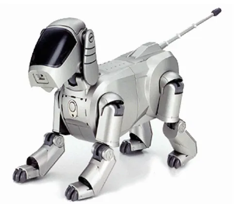
Figure 2.5: AIBO is a dog-like robot (Sony Corporation, 1999).
Figure 2.6: DuctCleaner Robot uses wheels to move around (LIFA AIR, 2008).
Figure 2.7: Nanokhod uses tracks to perform its locomotion (ESA, 2006).