UNIVERSITI TEKNIKAL MALAYSIA MELAKA
DESIGN AND DEVELOPMENT OF A SPHERICAL ROBOT
This report submitted in accordance with requirement of the Universiti Teknikal Malaysia Melaka (UTeM) for the the Bachelor‟s Degree in Electrical Engineering
Technology (Industrial Automation & Robotics) (Hons.)
by
NAZAMUDDIN BIN YUSUF B071110106
920525-03-6447
DECLARATION
I hereby, declared this report entitled “Design and Development of a Spherical Robot” is the results of my own research except as cited in references.
APPROVAL
This report is submitted to the Faculty of Engineering Technology of UTeM as a partial fulfillment of the requirements for the Bachelor‟s Degree in Electrical Engineering Technology (Industrial Automation & Robotics) (Hons.). The member of the supervisory committee is as follow:
……….
i
ABSTRAK
ii
ABSTRACT
A spherical robot is a two interconnected hemisphere with two rotary joints and one prismatic joint. This project is about designing and developing a spherical robot that can be controlled using wireless protocol. This project focuses on the performance of the robot while it performs the locomotion. A Spherical robot is designed to follow instructions from the smartphone via Bluetooth wireless communication. By using Bluetooth the limitation of using wired based control can be overcome. The spherical robot consists of spherical shells, Arduino Uno, L289P motor driver shield, Bluetooth module, Micro DC gear motor and graphic user interface (GUI). The mechanism of a spherical robot is using the wheel driven principle which the center of gravity is focuses at the bottom of the mechanical part. Thus, the mechanism used is still on its position when the spherical robot performs the locomotion. From the experiment, this spherical robot is capable to perform the locomotion in different terrains such as tar road, grass surface, cement surface and mosaic surface. The spherical robot also has also the ability to avoid the obstacle which obtains in front of it. The spherical robot is best performing on the tar road surface.
iii
DEDICATION
Specially.. To my beloved mother To my kind brothers and sisters
To my kind lectures And not forgetting to all friends
For their
iv
ACKNOWLEDGEMENTS
Assalamualaikum Warahmatullah Wabarakatuh.
First and foremost, I praise Allah, the Almighty and Merciful for providing me this opportunity and granting me the capability to proceed and finish this report successfully. It is a pleasure to express my deepest appreciation to all those who made this project and report possible.
I would like to express my deepest sense of gratitude to Mr. Aminurrashid Bin Noordin, my esteemed supervisor. My cordial thanks to him for his invaluable supervision, warm encouragement, thoughtful guidance, insightful decision, and critical comments throughout the project. I could not have imagined having a better supervisor and mentor for my Bachelor Degree project.
My deepest thanks go to all lecturers who have taught me, directly or indirectly, for all these four years of studies. I will never forget all the precious knowledge learnt and gained insyaAllah. I owe my deepest gratitude to Datin Fadzilah Binti Salim for helping me in my writing of this report. Her motivation has lightened me up throughout this project.
v
List of Symbols And Abbreviations xi
CHAPTER 1: INTRODUCTION 1
2.2 Spherical Robot Locomotion 8
vi
4.1 Electronic Development 31
4.1.1 Controller Decision 31
CHAPTER 5: RESULT AND DISCUSSION 48
5.1 The Performance of The Spherical Robot 48
5.1.1 The Locomotion Performance on Various Terrains 48
5.1.2 The Surface Suitability 50
5.2 The Robot Accuracy and Repeatability 51
5.3 The Performance of Robot Capability to Elude From Obstacle 54
CHAPTER 6: SUMMARY AND CONCLUSION 55
6.1 Summary 55
6.2 Conclusion 55
6.3 Recommendation 56
vii
REFERENCES 58
APPENDICES
A. The Programming Coding
B. Block diagram of Graphic User Interface (GUI) C. Configuration of L289
viii
LIST OF TABLES
2.1 Comparison range by class 14
3.1 Procedure of testing 27
4.1 The characteristics of the Arduino UNO 31
4.2 Specification of L289P Motor Shield 32
4.3 Button Description 47
5.1 The ability of robot to perform the pattern of locomotion 49
ix
LIST OF FIGURES
1.1 Overall Block Diagram 3
1.2 Overall System Flow 3
2.1 3D CAD view of assembly 5
2.2 The driving mechanism of the pendulum-driven type robot
6
2.3 Dominant form 7
2.4 Reconfigurable robot after transformation 7
2.5 The GSL mother-son robot system 8
2.6 Characteristics of the developed spherical robot 9
2.7 Block diagram of the robot system 9
2.8 The plane view of BYQ-IV 10
2.9 Motion model is equivalent to a pendulum 11
2.10 Gravity offset, reaction torque and their combination 12
2.11 The mechanical structure of SUR-II 12
2.12 Control-plant architecture 13
2.13 Bluetooth Localization Process Flow Overview 15
2.14 Communication between Host PC and Bluetooth Module
15
3.1 Methodology flowchart 17
3.2 Literature review flowchart 18
3.3 Designing flowchart 19
3.4 The simulation of motor 20
3.5 GUI designing flowchart 21
3.6 Fabrication flowchart 22
3.7 Assembling flowchart 23
3.8 Implementation of component flowchart 24
x
3.10 Accuracy Experiment procedure 28
3.11 Experiment procedure 29
4.1 Design Process 30
4.2 Arduino UNO 32
4.3 L289P Motor shield 33
4.4 Micro Metal Gearmotor HP 33
4.5 ZIPPY Compact Lipo Pack Battery 34
4.6 The HC-06 Bluetooth module 35
4.7 The drawing of spherical shell 36
4.8 The interconnected drawing of spherical shell 36
4.9 RP of spherical shell 37
4.10 Platform of the component drawing 37
4.11 Rapid Prototype of component platform 38
4.12 The empty slot drawing 38
4.13 RP of empty slot 39
4.14 Absorber drawing 39
4.15 RP of absorber 40
4.16 The mechanical drawing 40
4.17 The actual of mechanism of spherical robot 41
4.18 Program Flow Chart 42
4.19 The Bluetooth connection coding 43
4.20 The view of MIT app inventor 43
4.21 The GUI design 44
4.22 GUI form 44
4.23 Bluetooth connection block 45
4.24 Speed selection block 46
4.25 Direction selection block 46
4.26 Off and Initialize block 47
5.1 Surface Suitability 51
xi
LIST OF SYMBOLS AND ABREVIATIONS
PC - Personal Computer
GUI - Graphic User Interface
PID - Proportional-Integral-Derivative Controller
PD - Proportional-Derivative Controller
A/D - Analog To Digital
RF - Radio Frequency
R/C - Radio Controller
RP - Rapid Prototype
ABS - Acrylonitrile Butadiene Styrene
DC - Direct Current
GPS - Global Positioning System
UART - Universal Asynchronous Receiver/Transmitter
1
CHAPTER 1
INTRODUCTION
Recently, the spherical robot was really accustomed to many people because of the growth in technology. Many researchers and highest education institutions also show their interests in the growth development of the new innovative spherical robot with special characteristics and functions. What is a spherical robot exactly? The spherical robot is a robot consisting of two type of joints which are rotary joint and prismatic joint. An arm attached to the spherical robot forms a spherical coordinate system. The spherical coordinate system is a coordinate system for the three-dimensional space. Regardless of the characteristics of the spherical robot, the mechanical and control component of the robot were compressed inside the spherical shell and it provides great advantages to it. The spherical robot is proficient to accomplish the omnidirectional locomotion due to its spherical shape and geometrical symmetry. The variations of the design and purposes of the spherical robot show the attractiveness to the new researcher. This project is simply to design the spherical robot with the capability to perform omnidirectional locomotion and capable to control the motion of the robot using Bluetooth which applies to a smartphone.
1.1 Project objectives
The objectives of this project are as follows:
a. To design a spherical robot that can be controlled wirelessly using Bluetooth. b. To develop a graphic user interface (GUI) to control a robot locomotion using a
smartphone.
2 1.2 Project Scopes
By narrowing the needs for this project, a few guidelines are proposed to ensure that this project will achieve its objectives. The scopes covered for this project are:
i. To design a 12cm diameter of spherical robot that can be controlled wirelessly using Bluetooth by utilize the serial communication protocol and using Arduino Uno as a controller to control the robot.
ii. To develop graphic user interfaces (GUI) of MIT app inventor to control the locomotion using a smartphone
iii. To analyze the locomotion of the spherical robot on five different surfaces and tabulate the data.
1.3 Problem statements
The mechanical issues are very important in a spherical robot especially for its locomotion due to its spherical shape, arrangement of the components and the size of the robot itself. There are several principles can be used to implement the mechanical part for the spherical robot such as the wheel driven principle, the gear and pulley principle and pendulum principle. For this project the principles of wheel driven principle was used to ensure the locomotion of the robot due to its application and more practical.
3 1.4 Project Overall System
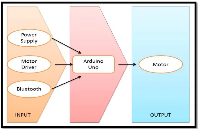
At the input block, there are a power supply unit, a Bluetooth module and L289P driver motor shield. This project uses Arduino Uno as a controller and it control two DC motor as illustrated at output block. Figure 1.1 shows the overall block diagram for this project.
Figure 1.1: Overall Block Diagram
The spherical robot is controlled by GUI which was developed into a smartphone which communicate using Bluetooth module as it transmitter. The developed GUI controls the movement of the spherical robot. The overall system flow is shown in Figure 1.2.
4 1.5 Thesis Outline
The structure and layout of the thesis are as follows:
Chapter 1 – Introduction: This chapter discusses a short introduction on the project which covers the objectives, scopes of the project and the problem statements.
Chapter 2 – Literature Review: This chapter describes what is a spherical robot and the existing spherical robot which have been developed by the previous researchers. It also consist of the information which will be the parameter for developing this project
Chapter 3 – Methodology: This chapter discourses the methods used for developing the project and also approach taken in order to complete the project.
Chapter 4 – Project Development: This chapter deliberates about the early conceptualization stage in designing of the robot until it completion. The hardware parts, electrical and electronics parts and the software used will be highlighted.
Chapter 5 – Results and Discussion: This chapter expresses the result and findings of the experiment. The findings results were analyzed and discussed. The problem encountered in this project will be highlighted as well.
5
CHAPTER 2
LITERATURE REVIEW
This chapter reviews the articles and journals related to this project. Similar products have been developed by researchers in other higher learning institutions previously. The theory and implementation of the components, equipment and programming language used in the previous project are discussed here.
2.1 Spherical Robot Design
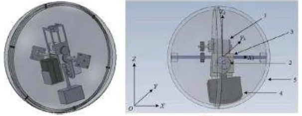
Deepak Pokhrel et al. (2013) stated that the spherical robot may be the most significant design due to its easy maneuverability, holonomic nature and omnidirectional movement. The pendulum-based drive system is used as a driving mechanism due to its relatively simple design. There are boundless restrictions on how the shell is made. The design consists of three basic units which are namely as an outer shell, inner drive unit and pendulum arrangement as shown in Figure 2.1. The gear drive is used in order to keep the mechanical design simple and powerful. Two halves of spherical shell design is used to ease the manufacturing and assembly.
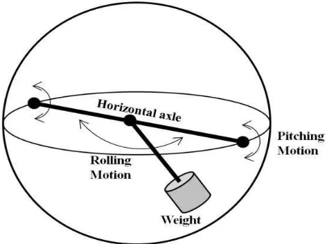
6 Jayoung Kim et al. (2009) introduced the pendulum–driven spherical mobile robot. The glass fiber sticks are chosen as an external frame of the robot due to their good elastic characteristics. All the control modules are embedded into the spherical mobile robot and the Atmega 2560-based embedded system is used as the main controller to drive the robot. The implementation of PID controller is verified based on good mobility of the robot. The pendulum-driven spherical robot was a dynamic model for steering motion and analyzing driving. The driving mechanism of the pendulum-driven type robot is shown in Figure 2.2.
Figure 2.2: The driving mechanism of the pendulum-driven type robot
7 Figure 2.3: Dominant form
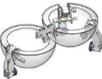
Figure 2.4: Reconfigurable robot after transformation
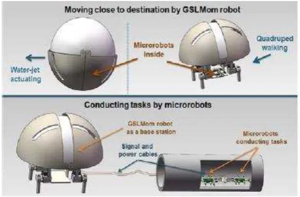
8 Figure 2.5: The GSL mother-son robot system
2.2 Locomotion of Spherical Robot
Qiang Zhan et al. (2011) designed a novelty spherical robot with omnidirectional which composed of a lucent ball-shaped shell and an internal driving unit. To attain the omnidirectional motion of the robot, two motors were installed on the internal driving unit. One motor was used to perform straight movement and another one was used to make it steer. The spherical robot was used barycenter principle offset to drive the center of gravity which deviates from the static position. By applying that, it can break the system balance when the gravity moment were produced and cause the robot to roll.
9 Figure 2.6: Characteristics of the developed spherical robot
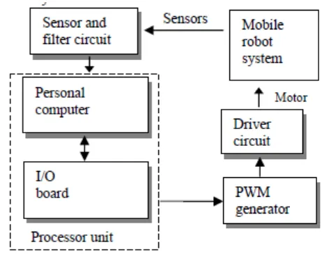
Ya-Fu Peng et al. (2009) implemented an omnidirectional spherical robot using fuzzy control. The robot can move directly in any direction with no constraint and the fuzzy control is introduced to control the locomotion of the robot. Fuzzy control can deal with the unknown nonlinearities and external disturbance. Fuzzy control method was based on the human experience to understand the behavior of the system and fuzzy control was simple in designing. Fuzzy control systems were designed around personal computer and comprise same hardware components. The block diagram of the Fuzzy control system is shown in Figure 2.7.
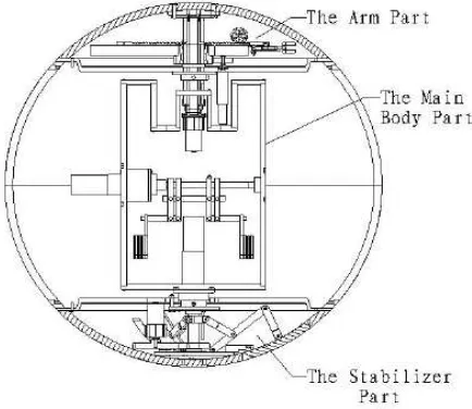
10 Zheng Yili et al. (2008) designed an omni-directional rolling spherical robot with telescopic manipulator (BYQ-IV) as shown in Figure 2.8. Other than performing straight line motion, circular motion, zero turning radius and obstacle avoidance it is also capable to carry out the tasks by grabbing and delivering assemblies. The robot was allotted into three subs-systems which are the motion driving system; the manipulator system and the stability maintain system. The ARM processor and wireless communication system are pioneered as the distributed control system.
Figure 2.8: The plane view of BYQ-IV
2.3 Control Motion