Design and Development of Knee and Ankle
Rehabilitation Robot Based on Indonesian
Anthropometric Data
Widhi Yoga Saryanto
*, Herianto
+, Adha Imam Cahyadi
#*
Dikti Fast track Program 2012, Department of Mechanical and Industrial Engineering Universitas Gadjah Mada, Yogyakarta, Indonesia
+
Department of Mechanical and Industrial Engineering Universitas Gadjah Mada, Yogyakarta, Indonesia
#
Department of Electrical and Information Engineering Universitas Gadjah Mada, Yogyakarta, Indonesia
Abstract
The demand of using assistive devices for impairment limb has been increased. The researchers design and develop rehabilitation robot to help post stroke patient get the exercise to strengthen their impairment limbs body part especially knee and ankle joint. This robot is composed of two link of which each has different gear box to increase the torque. In this preliminary design, it is integrated with open loop control system and designed based on Indonesian Anthropometric Data.
Key words –Stroke, Rehabilitation Robot, Design, Anthropometric
I. INTRODUCTION
In Asian country, stroke is the second top cause of death at the age of more than 60 years as well as fifth top cause in the age of 15-59 years. Currently, Indonesia is ranked first by the largest number of stroke patients in Asia. In Indonesia, approximately 500,000 people every year suffered stroke, in which about 25% or 125,000 people died, and the rest have mild or severe disability [1]. Nowadays, stroke becomes an important and urgent issue that must be handled.
Stroke is a brain attack, which suddenly emerges due to clogged or broken blood vessels of the brain. This condition is resulting in a reduction of blood flows in the brain, causing a series of biochemical reactions, which can be a devastating or deadly effect for nerve cells in the brain. Death of brain tissue can cause a loss of function that is controlled by the tissue [2]. Post-stroke patients generally suffer paralysis in the limbs, partial loss of memory and speech even death.
Stroke rehabilitation is a recovery program for stroke conditions that aim to optimize physical capacity and functional ability of the post stroke patients. By using rehabilitation process, post-stroke patients are expected to be independent in performing daily activities.
In Indonesia, the process of rehabilitation and stroke therapy is usually performed in a hospital that provides
medical rehabilitation installation. Patients is required to come to the hospital periodically based on the schedule of therapy provided by the hospital. Then some therapists help patients to perform rehabilitation movements.
As the number of post-stroke patients is increased, it takes more physiotherapy to help post-stroke patients [3]. Manual rehabilitation is not precise, not repeatable. Moreover it is slow, and adds burdens to human therapists [4]. To facilitate the rehabilitation process, a tool is developed to assist the rehabilitation process. By using rehabilitation tool, the rehabilitation of post-stroke patient can be performed anywhere and anytime. Rehabilitation robots aim to solve daily living problems in individual activities [5]. The ability of robots to deliver training with high intensity and repeatability make them very valuable assistive tools to provide high quality treatment at a lower cost and effort. [6]
In earlier research conducted by Herianto et al, a robot to assist the rehabilitation of lower limbs was successfully designed and implemented [7]. However, their research did
not integrate control system in the robot. Moreover, the
actuator torque and speed is not appropriate with the needs of post-stroke patient.
This study proposes and develops a rehabilitation robot that assist the rehabilitation of lower limb post stroke patients. More importantly, the rehabilitation robot designed and developed based on Indonesian anthropometric [8].
In this study, the open-loop control system was developed. In addition, this research also developed a new actuator by adding the gear box so that the torque and speed can be adjusted to the needs of post-stroke patients. This study focus on the development of lower limbs rehabilitation robot due to lower limb is an important part of the body that play a role in the movement and activity of the body, especially walking. Rehabilitation robots are designed to assist foot rehabilitation
passively on the knee and ankle
.
Page 413 of 436
II. ROBOT DESIGN A. Robot Design
Robot was designed using Autodesk Inventor 2012 ™
software. Robot design is adjusted to the Indonesian anthropometry. The robot, consists of two link manipulators, is shown in Fig 1. Link 1 works for knee rehabilitation, while link 2 works for ankle rehabilitation. This robot is designed to be portable and easy to disassembly.
Fig.1. Knee and Ankle Rehabilitation Robot.
B. Gear Box Design
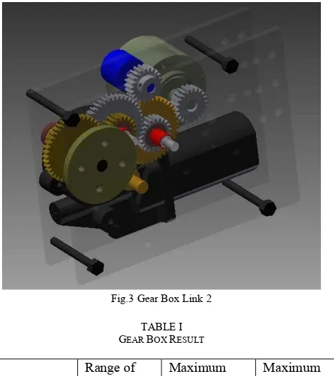
Prototype rehabilitation robot uses two motors as drive which assembled in the gear box. Gear box consists of an incremental rotary encoder, potentiometer, and also some gear to reduce the motor rotation. We use two kinds of motors ,i.e., wiper motor and power window motor used in automobile. To obtain sufficient torque, the gear ratio is required at 1:8. Its aim to generate greater torque to make is to make it easier when used in the real patients. Gear box link 1 is shown in Fig.2 and gear box link 2 is shown in Fig.3.
Fig.2 Gear Box Link 1
Fig.3 Gear Box Link 2
TABLE I GEAR BOX RESULT
Joints
Range of motion (degree)
Maximum torque of actuator (Nm)
Maximum angular velocity of actuator (rpm)
Knee joint 0 – 130 81.6 17
Ankle joint 0 – 60 22 13.6
III.ROBOT MANUFACTURE
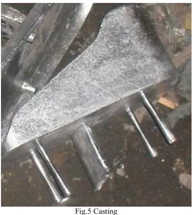
Rehabilitation robot that developed was manufactured by machining and casting methods as shown in Fig.4 and Fig.5. The robot material uses aluminium because aluminium is a metal which lightweight and easily manufactured.
Fig.4 Machining
Page 414 of 436
Fig.5 Casting
IV.ASSEMBLY AND PROGRAMING
This study uses two types of sensors. They are incremental rotary encoder and potentiometer. Rotary encoder is used to determine angular velocity while the potentiometer is used to determine the initial position of the link. Henceforth, angle is known from incremental rotary encoder. The reading velocity of the rotary encoder is known by reading the difference in pulses per 10 milliseconds. For complete revolution, it generates 115200 pulses. The equations to calculate angular velocity as follows
(1)
, (2)
where
S = Difference in number of pulses per 10 ms Angular velocity (rpm).
For the reading of the angle, it is done in the following way
,
where
P = Number of pulses A = Angle (degree).
Angular velocity and the angle are set with an open loop control system. Open loop control system diagram is shown in Fig.6. Motor moves based on the program of the microcontroller.
Fig.6 Open Loop Control System Diagram
This study uses Pulse Width Modulation as an input to the actuator. Therefore, it is necessary experiments to determine the relationship between PWM as input and angular velocity as its output. This is done to make it easier to determine the angular velocity as a set point when programming. From these experiments, we will know the mathematical equation and this equation that will be incorporated into the program in the microcontroller. Relation between PWM and angular velocity are shown in Fig.7 and Fig.8.
Fig.7 Pulse Width Modulation and Angular Velocity Link 1
Fig.8 Pulse Width Modulation and Velocity Link 2
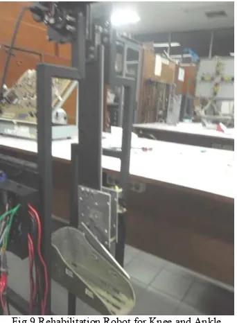
From the experimental results, it can be seen that for Link 1 can be approximated by the first order equations, while for the Link 2 can be approximated by a second order equation. Then, the equation is inserted into the microcontroller program. The rehabilitation robot that we developed is shown in Fig.9.
Page 415 of 436
Fig 9 Rehabilitation Robot for Knee and Ankle
V. ROBOT PERFORMANCE
At this stage, we tested the robot performance that has been made. The first test was conducted comparing the desired angle with the angle formed by the actuator. The second test is to compare the desired angular velocity with angular velocity formed by the actuator.
Fig.10 Response of the Angle
The graph in Fig.10 shows that the angle formed by the actuator could follow the angle of the program even though
there are some corners that do not proper. However, the
difference between the desired angle with the angle in actuator is no more than 5 degrees for Links 1 and 3 degrees for Link 2. The error occurred because the backslash in the gear box. Backslash Link 1 is greater than Link 2 because the gear module of Link 1 is greater than Link 2. While testing the angular velocity is shown in Table II.
TABLE II
COMPARISON BETWEEN THE INPUT ANGULAR VELOCITY WITH ACTUAL ANGULAR VELOCITY
From Table II, it is known that the desired angular velocity is the same as the angular velocity of the actuator although there are some errors.
V. CONCLUSIONS AND FUTURE WORK
In this research, rehabilitation robot to assist in the rehabilitation of knee and ankle successfully designed and manufactured. In performance testing, the robot has shown satisfactory results. This is due to the resulting error is relatively small. From the test results, the error in the angle of link 1 is not more than 5 degree and the error angle in link 2 is not more than 2 degree. In the test of angular velocity, the error in both link are not more than 2 rpm. The angle error and angular velocity error are caused by a backslash in the gear box. Using a gear box will increase the torque but in other hand it will cause increased backslash on the system. For the future, the gear is made with stronger material and uses smaller gear modules so that losses can be minimized.
REFERENCES
[1] http://www.yastroki.co.id accessed at 1 August 2014
[2] Arga Sadhewa, Herianto.,”Desain dan Manufaktur Robot Rehabilitasi Kaki Kanan Pasien Pasca Stroke dengan Modular Plat untuk metode Rentang Pergerakan Sendi Pasif, 2013, unpublished
[3] Widhi Yoga Saryanto, Herianto,. “Pengembangan Prototype Arm Robot dengan Original Servo Motor”. 2013. .Seminar IENACO
[4] S. M. Mizanoor Rahmana,, Ryojun Ikeura..2012.” A Novel Variable Impedance Compact Compliant Ankle Robot for Overground Gait Rehabilitation and Assistance”. Procedia Engineering 41 ( 2012 ) 522 – 531, International Symposium on Robotics and Intelligent Sensors 2012 (IRIS 2012)
[5] Pyung-Hun Chang et al,.2004. “Integration of a Rehabilitation Robotic System (KARES II) with Human-Friendly Man-Machine Interaction Units” Kluwer Academic Publishers. Autonomous Robots 16, 165–191, 2004
[6] I˜naki D´ıaz, Jorge Juan Gil, and Emilio S´anchez.2011.” Lower-Limb Robotic Rehabilitation: Literature Review and Challenges”. Journal of
Robotics Volume 2011, Article ID 759764, 11 pages
doi:10.1155/2011/759764
[7] Herianto et.al., “Desain dan Pengembangan Alat Bantu Rehabilitasi Stroke untuk Anggota Gerak Bawah”,Annual Engineering Seminar 2014, pp A73-A78, Februari 2014.
[8] Tan Kay Chuan, Markus Hartono, Naresh Kumar., “Anthropometry of the Singaporean and Indonesian populations”, International Journal of Industrial Ergonomics 40 (2010) 757-766.