DIRECT MODELLING CAD STUDY FOR PRODUCT
DEVELOPMENT PROCESS
SITI ZULAIKHA BINTI ABDUL MUTALIB
B071110309
UNIVERSITI TEKNIKAL MALAYSIA MELAKA
DIRECT MODELLING CAD STUDY FOR PRODUCT
DEVELOPMENT PROCESS
This report submitted in accordance with requirement of the Universiti Teknikal Malaysia Melaka (UTeM) for the Bachelor’s Degree in Manufacturing Engineering
Technology (Product Design) Hons.
by
SITI ZULAIKHA BINTI ABDUL MUTALIB
B071110309
920806-04-5526
UNIVERSITI TEKNIKAL MALAYSIA MELAKA
BORANG PENGESAHAN STATUS LAPORAN PROJEK SARJANA MUDA
TAJUK: Direct Modelling CAD Study For Product Development Process
SESI PENGAJIAN: 2014/15 Semester 1
Saya SITI ZULAIKHA BINTI ABDUL MUTALIB
mengaku membenarkan Laporan PSM ini disimpan di Perpustakaan Universiti Teknikal Malaysia Melaka (UTeM) dengan syarat-syarat kegunaan seperti berikut: 1. Laporan PSM adalah hak milik Universiti Teknikal Malaysia Melaka dan penulis. 2. Perpustakaan Universiti Teknikal Malaysia Melaka dibenarkan membuat salinan
untuk tujuan pengajian sahaja dengan izin penulis.
3. Perpustakaan dibenarkan membuat salinan laporan PSM ini sebagai bahan pertukaran antara institusi pengajian tinggi. atau kepentingan Malaysia sebagaimana yang termaktub dalam AKTA RAHSIA RASMI 1972)
(Mengandungi maklumat TERHAD yang telah ditentukan oleh organisasi/badan di mana penyelidikan dijalankan)
(TANDATANGAN PENULIS)
DECLARATION
I hereby, declared this report entitled “Direct Modelling CAD Study For Product Development Process” is the results of my own research except as cited in
references.
Signature : ……….
Author’s Name : Siti Zulaikha binti Abdul Mutalib
APPROVAL
This report is submitted to the Faculty of Engineering Technology of UTeM as a partial fulfillment of the requirements for the degree of Bachelor of Engineering Technology Manufacturing Engineering Technology (Product Design). The member of the supervisory is as follow:
ABSTRAK
ABSTRACT
DEDICATION
I love to bestow my dedication of this thesis for, First and foremost,
My Lord, Allah S.W.T the Most Gracious and the Most Merciful, Messenger of Allah S.W.T, Muhammad S.A.W,
My beloved parents, Abdul Mutalib and Norhayati, Thoughtful siblings, Aishah and Amiruddin, Supportive Supervisor, Mr Mohd Qadafie bin Ibrahim, Respected lecturers of Faculty of Engineering Technology (FTK), Fellow friends that lend hands and gave words of encouragement,
ACKNOWLEDGEMENT
TABLE OF CONTENTS
List of Abbreviations viiii
CHAPTER 1: INTRODUCTION
2.3 Reasons for Implementing CAD 9
2.4 CAD Benefits 12
2.5.1 Types of Modellers 14
2.6 Geometric Modelling 16
2.7 Wire Frame Modelling 20
2.8 Surface Modelling 21
2.9 Solid Modelling 22
2.9.1 Constructive Solid Geometry 23
2.9.2 Boundary Representation 24
2.10 Parametric Modelling 26
2.11 Direct Modelling 27
3.6 Comparisons Study 42
4.3 Parametric CAD Modelling of The Hand Dryer 44
4.3.1 Encounter Problem During Modelling Process 47
4.4 Direct CAD Modelling of The Hand Dryer 49
4.4.1 Encounter Problem During Modelling Process 51
4.5 Comparisons Study 54
4.5.7 Graphics User Interface (GUI) 64
4.6 Design Process 68
4.7 Product Design And Development (PDD) 68
CHAPTER 5: CONCLUSION & FUTURE WORK
2.2 Recommendations For The Future Works 73
REFERENCES xiv
LIST OF TABLES
2.1 Top 10 UK CAD packages 10
2.2 Advantages and disadvantages of surface modelling 22 2.3 Comparison of history-based modelling and direct modelling 29
4.1 Standard parts 42
4.2 Part designed in SolidWorks software 44
4.3 Manually adjusting the sketch to change feature 47
4.4 Part designed in SpaceClaim software 49
4.5 Directly change the part features without concerning part sketch 51
4.6 Parametric CAD modelling mouse clicks 54
4.7 Build solid and cutting hole using parametric modelling 56 4.8 Build solid and cutting hole using direct modelling 57 4.9 Before and after the “Escape” button was pressed 59
LIST OF FIGURES
1.1 Sketchpad software console developed by Ivan Sutherland 2
2.1 Cathode ray tube 8
2.2 Percentages of Top 10 UK CAD packages 11
2.3 Modelling and CAD timeline 11
2.4 Component parts weights evaluated by CAD system 12
2.5 Improvement in image visualization for various drawing types 13 and computer graphic features
2.6 CAD data formats used by design department as the respondent 15
2.7 Typical Shigley’s design process 16
2.8 Two dimensional object 17
2.9 2 1/2D object – composite 17
2.10 3D modelling from CATIA Spatial software 18
2.11 Wire frame model 19
2.12 Surface modelling 19
2.14 Simple 3D wireframe model 20
2.15 Rectangular and triangular surface patches 21
2.16 Solid model terminology 22
2.17 Constructing a solid with 3D primitives in solid modelling in CSG model 24
2.18 Chamfering an edge in an object 24
LIST OF FIGURES
2.20 Basic elements of data structure 25
2.21 Creating parametric features 26
2.22 Direct editing a cylindrical part 28
3.1 3D mouse – SpacePilot Pro 31
3.2 Cintiq’s full set hardwares 31
3.3 SolidWorks icon 33
3.4 SpaceClaim icon 33
3.5 Mouse Clickr interface 34
3.6 Emphasis flow chart 35
3.7 Softener bottle as benchmark product 39
3.8 History-tree based 40
3.9 Bottle before modification takes place 40
3.10 Bottle cap 41
3.12 Bottle before modification 42
3.13 Bottle cap 42
3.14 Parametric modelling clicking point area 43
3.14 Direct modelling clicking point area 44
LIST OF FIGURES
4.1 Hand dryer 41
4.2 Exploded view of the hand dryer 44
4.3 Errors shown when changing the 70⁰ edge fillet angle to 130⁰ 48
4.4 Ten steps with 16 clicks to make connecting wire using swept boss feature 48 4.5 The best view to sketch the side-to-side slotting line of hand dyer 49 4.7 No error to be found after 70⁰ edge fillet angle was changed to 130⁰ 52
4.8 Nine steps with 11 clicks to make connecting wire using swept boss feature 53
4.9 Cross sectional view that enable user to sketch on the selected face 53
4.10 Number of clicks for both modelling 55
4.11 Mouse gesture of the parametric modelling applied in SolidWorks software 60 4.12 Mouse and touch gesture of the direct modelling applied in SpaceClaim software 61 4.13 One of the error dialogue balloon when error occurred while mating two parts 62
4.14 Assembly features in SpaceClaim software 62
4.15 Selecting SolidWorks new documents 64
4.16 Selecting SpaceClaim new documents 65
4.17 Design tab that include sketch tool, feature builder tool and assembly tool 65
4.18 Overall UI for SolidWorks 65
4.19 Sketch tab that organize sketch tool 66
4.20 Features tab that organize features builder of part tool 66
4.21 Overall UI for SpaceClaim 66
LIST OF FIGURES
4.23 SpaceClaim drawing sheet 67
4.24 SpaceClaim drawing sheet in 3D model 67
LIST OF ABBREVIATIONS, SYMBOLS AND
NOMENCLATURE
CAD - Computer Aided Design
CAD/CAM - Computer Aided Design /Computer Aided Manufacturing CPU - Central Processing Unit
MCAD - Mechanical Computer Aided Design IGES - Initial Graphics Exchange Specification CNC - Computer Numerical Control
BRep - Boundary Representation
CSG - Constructive Solid Geometry
NURBS - Non-Uniform Rational B-Spline WYSIWYG - What You See Is What You Get
LIST OF ABBREVIATIONS, SYMBOLS AND
NOMENCLATURE
UI - User Interface
1 This chapter will clarified with brief on the basic understandings of the study which gives an overview of the parametric modelling CAD system and direct modelling CAD system. Essentially, it comprises of four main sections which are background, statement of purposes problem statements, objectives and work scopes where it portrays the whole process involved in this study.
1.1 Background
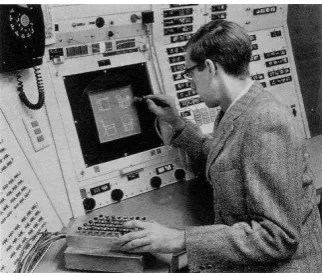
The application of Computer Aided Design (CAD) in the recent industry is not something brand-new to be heard about. This is because CAD software has been existed about five decades ago around year 1963. The history was guided by Ivan Sutherland with the development of Sketchpad which is also known as robot drafting was a ground-breaking computer program (Matthias, M. P., 2006). Referring to Figure 1.1, Sketchpad was handled with a light pen and a command button box
which is located under the left hand. The four black knobs below the monitor screen functioning to control position and scaling part design.
INTRODUCTION
2 Figure 1.1: Sketchpad software console developed by Ivan Sutherland (1963)
According to Rao (2010), Computer Aided Design (CAD), use computer as a mechanism for all functions that are involved in the design process. Where the core purpose of the computer are that the layout design for comprehensive assembly, single component modelling, assembly modelling, interference and tolerance stack checking as well as engineering drawing.
Nowadays, CAD technology is a really high up issues because all the cost, time consumption as well as quality rely on it. Concerning technology development that changes rapidly, CAD technology is taking a few steps ahead to help designers create products that will marvel the customer as well as the end user. Up to this point, there are pile of CAD technologies accompanied the industry worldwide. This also includes the parametric modelling technology and direct modelling technology that will be the focus points of this study.
3 On the other hand, the new kind of developed technology which is direct modelling technology emphasis on to make the product model that drop the constraint issues made by the parametric modelling technology despite do not keep the initial design intent. So, the designer can design their model at ease and more intuitive. Comparing with the parametric modelling, direct modelling has no history tree or being recognized as history-free modelling by Paul (2010). In different with parametric approaches, history-free technology more likely to be flexible modelling process, does not have parent/child relationship rather editing are typically direct where it just involving the change of geometry.
1.2 Statement of the Purposes
CAD/CAM work together in that the digital model generated in CAD is inputted to the CAM software package. The CAM software need to know the product physical shape which is CAD model before it can plan a proper set of fabrication instructions to a production machine.
This project will emphasis more on the design drawing process before it is transfer to CAM software. This project will steer on the current development of CAD technologies and aiming on the direct modelling technology research. In addition, this project also covers the comparison of the parametric modelling CAD and the direct modelling CAD. The comparisons also include the Product Design and Development (PDD) in a design flow process.
4
1.3 Problem Statements
This study outlines two problems regarding parametric CAD system issues which are difficulties in learning curve and less flexibility in the design process. These kinds of problems lead to the lack of proficient worker that generate product with quality and dragging product development time consumption respectively.
Parametric CAD system is quite difficult to learn. Due to this, manufacturer or any company that utilized parametric CAD system need to send their worker for training which obviously raise the cost of the company on worker upgraded skill. Besides that, inflexibility of design process also contributes troubles to the worker especially when there are changes in drawing design.
1.4 Objectives
There are two objectives to be accomplished by the end of this study which are:
(a) To evaluate direct modelling in CAD technology
(b) To compare design process between parametric modelling and direct modelling
(c) To establish work flow for Product Design and Development (PDD) using direct modelling software
1.5 Work Scopes