Electrophoretic Deposition and Heat Treatment of Steel-Supported
PVDF-Graphite Composite Film
Kok-Tee Lau
1, a,
Mohd Hafrez Razi Ab Razak
1, Swee-Leong Kok
2,
Muhammad Zaimi
1, Mohd Warikh Abd Rashid
1, Noraiham Mohamad
1and Mohd Asyadi Azam
11Carbon Research Technolgy Group, Faculty of Manufacturing Engineering, Universiti Teknikal
Malaysia Melaka, Hang Tuah Jaya, 76100, Durian Tunggal, Melaka, Malaysia
2Faculty of Electronic and Computer Engineering, Universiti Teknikal Malaysia Melaka, Hang Tuah
Jaya, 76100, Durian Tunggal, Melaka, Malaysia
Keywords: Piezoelectric material, Electrode, Non-aqueous suspension, Cantilever-based accelerometer, Sequential deposition
Abstract. Polymeric poly(vinyliden fluoride) (PVDF) is nontoxic. It possesses a better mechanical flexibility and requires a lower synthesis temperature, as compared to the piezoceramic counterparts. In order to achieve a competitive advantage against the current piezoelectric sensor, graphite could replace a more expensive silver-palladium as the electrodes for the piezoelectric PVDF. This paper reports the preliminary results on the synthesis of steel-supported graphite-PVDF/PVDF/graphite-PVDF composite films using the two-step process, consisted of the electrophoretic deposition (EPD) and heat treatment. The composite films were characterized by means of the optical microscopy, scanning electron microscopy, X-ray diffraction and differential scanning calorimetry. The heat treated graphite-PVDF electrode deposited by EPD provides adequate mechanical strength for the subsequent depositions of pure PVDF layer and the second layer of graphite-PVDF composite electrode. However, the final heat treatment stage did not eliminate the fine and large cracks of the composite film, which might be attributed to high residue stresses and weak bonding between graphite and PVDF particles in the post-heat treated composite films. Nevertheless, the increase in final heat treatment temperature of the composite film at Stage 3 improved the graphite and PVDF grain alignment, as well as its crystallinity.
Introduction
Polymeric poly(vinyliden fluoride) (PVDF) [1] is widely used as an alternative piezoelectric material to lead zirconate titanite (PZT) [2] and BaTiO3ceramics [3,4] because of its better
mechanical flexibility and lower fabrication temperatures. Although the piezoelectric performance of PVDF is lower than the piezoceramic counterpart [1], the superior piezoelectric properties could be obtained by the synthesis of a free-standing piezoelectric film, instead of a conventional substrate-supported piezoelectric film [5]. On the other hand, the micron-range thickness control of PVDF film and the addition of electrodes on the PVDF film are difficult to be accomplished using the spin-coating [3,6] or casting techniques [3,7]. Furthermore, the techniques require a total detachment of the film from the supported substrate [6]. Although it is possible to sequentially deposit the electrode and piezoelectric film using the screen-printing technique, the mixing of PVDF powder with an organic binder may trigger undesired chemical reaction during the subsequent heat treatment at an elevated temperature. Alternatively, the electrode/PVDF/electrode-layered composite film could be easily deposited by a non-aqueous electrophoretic deposition (EPD) technique, where first electrode layer, PVDF layer, and second electrode layer can be deposited sequentially by changing the suspension of EPD from graphite to PVDF and then back again to graphite. In addition, a free-standing electrode/PVDF/electrode composite film on the supporting substrate can be synthesized if a thin sacrificial water-soluble layer is deposited prior to the deposition of the electrode/PVDF/electrode layer onto the supporting substrate. The
soluble layer can be removed in the final synthesis stage by the immersion of the water-soluble sacrificial layer/electrode/PVDF/electrode layer in the water.
The current paper reports the preliminary microstructural, phase compositional and thermal results of the steel-supported graphite composite/PVDF/graphite composite film synthesized using the EPD technique, as well as revealing the potential of graphite as a cheaper alternative electrode material compared to silver-palladium. The study is hoped to pave the way for the synthesis of a high performance low cost cantilever-based accelerometers for the motion or vibration sensor application.
Experimental Details
The suspensions for the EPD of PVDF layer and graphite composite layers were prepared separately. The PVDF suspension with a concentration of 0.01 g/mL was prepared by adding the PVDF powder (purity: 99.99 wt%, Sigma-Aldrich Co.) into a solution mixture of 95 vol% 2-butanone−5 vol% distilled water and magnetic-stirred at 60°C for about two hours. The
graphite-PVDF suspension mixture with a concentration of 0.4 g/mL was prepared by adding graphite (99.8 wt%, Merck & Co.) and PVDF powders at the ratio of 25:75 wt% into the organic mixture of 80 vol% acetone−20 vol% n-butylamine and magnetic-stirred at room temperaturefor 30 min. Prior to
EPD, both suspensions underwent ultrasonification for 5 min. EPD was performed using a set-up of DC power supply (model: OWL EC1000XL2, Thermo Fisher Scientific), connected to two identical AISI316-grade stainless steel electrode plates (dimensions: 2 cm×1 cm×0.4 mm) with a fixed
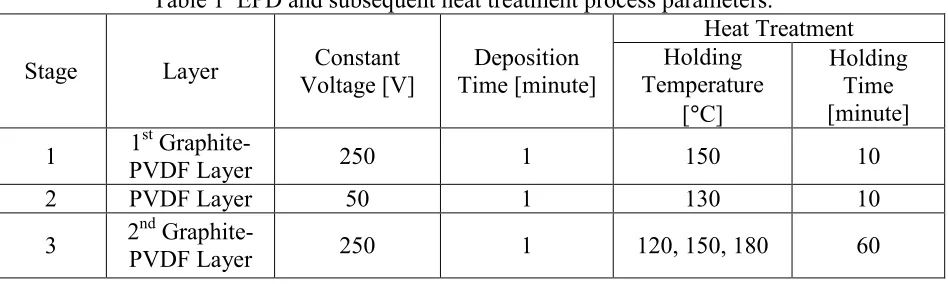
electrode separation of 1 cm. First, graphite-PVDF composite was deposited on the depositing steel substrate. It was followed by PVDF layer and finally the second layer of graphite-PVDF composite. In order to increase the structural strength of the deposit layers, they were subjected to heat treatment prior to the subsequent deposit layer. With the same purpose, a final heat treatment was conducted on the complete graphite-PVDF/PVDF/graphite-PVDF deposit to consolidate the second layer of graphite-PVDF composite layer. More details of these process parameters are listed in Table 1. Surface microstructures of the deposited layers were captured using the optical (Model: EMZ-13TR, Meiji Techno) and scanning electron microscopy (scanning electron mode, accelerating voltage = 15 kV, Model: Evo 50, Carl Zeis AG). The phase composition was investigated using glancing angle X-Ray Diffraction (Cu Kα radiation, glancing angle = 1.5°,
scanning speed = 6°/min, Model: X’pert PRO, PANalytical B.V.). The thermal analysis was
conducted using the differential scanning calorimeter (mass per run= 10 mg, aluminium crucible, heating rate = 10°C/min, nitrogen gas environment with flow rate of 20 mL/min).
Table 1 EPD and subsequent heat treatment process parameters.
Stage Layer Voltage [V] Constant Time [minute] Deposition
Results and Discussion
Fig. 1 Surface Appearance of the deposited and post-heat treated layer at different stages and their location in the deposited composite film (schematic image).
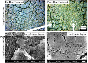
Fig. 2 Optical Image (magnification of 50×): Surface microstructures of top (final) layer of
graphite PVDF/PVDF/ graphite-PVDF composite film before and after heat treatment. SEM Micrograph (magnification of 5000×): Large and fine cracks regions on the post-heat
treated film.
Fig. 1 shows the photographic images of the surface appearance of the deposited graphite-PVDF, PVDF and PVDF layers after the Stages 1, 2 and 3 of the synthesis of the graphite-PVDF/PVDF/graphite-PVDF laminated composite film. The post-heat treated graphite-PVDF composite was used as the electrode layer material because we observed that it could eliminate deposit loss of electrode layer during EPD of the PVDF layer, which happened when pure graphite layer was deposited (image was not shown). A possible improved mechanical strength of the
(Post-Heat Treatment)
2 µm
0.2mm
2nd Layer of Graphite
PVDF Layer 1st Layer of Graphite
graphite-PVDF electrode layer may be due to an increase in contact surface of the graphite-PVDF with the PVDF, resulted from the presence PVDF particles in between the graphite particles. However, the uneven surface of complete graphite-PVDF/PVDF/graphite-PVDF film (Fig. 1) implies deposit loss either from the PVDF or second graphite-PVDF layer, occurred probably during EPD in Stage 3. It was found that final heat treatments at 120-180°C at an extended heating
time (Fig. 2) could not reduce cracks in the composite film. The presence of large and fine cracks before and after the heat treatments is probably due to the weak bonding and uneven deposition of PVDF and graphite particles in both the electrode and PVDF layers.
Fig. 3 XRD spectra of graphite-PVDF/PVDF/graphite-PVDF composite films after heat treated at different temperatures in Stage 3, synthesis process.
Fig. 3 shows the XRD spectra of the graphite-PVDF/PVDF/graphite-PVDF composite films heat treated at different holding temperatures, characterized after the completion of Stage 3 of the synthesis process. As shown in the figure, the graphite peak is higher than PVDF because of its higher crystallinity as compared to the latter. Furthermore, the increase of XRD peak intensities of graphite and PVDF when the holding temperature increased from 120°C to 180°C is possibly due to
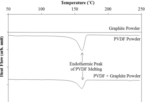
the increasing grain alignments of the graphite and PVDF particles triggered by the melting of the PVDF grains. The DSC endothermic peak of PVDF melting was observed at the onset temperature of 140°C (Fig. 4). The reduced PVDF peak intensity is due to the decrease in vol% of PVDF used
for DSC measurement (mixture ratio of PVDF to graphite powder is 50:50). The absence of new peaks in the DSC curve of PVDF-graphite mixture as compared to the peaks shown in DSC curve of PVDF (no peak was observed for graphite) suggests no chemical reaction takes place between the PVDF and graphite powder at the studied temperatures.
Conclusion
Steel-supported graphite-PVDF/PVDF/graphite-PVDF composite film was synthesized using electrophoretic deposition technique and a subsequent heat treatment process. The deposition and heat treatment of the graphite-PVDF composite electrode layer provide an adequate mechanical strength that enables the subsequent deposition of PVDF layer and the second layer of graphite composite layer. However, the final heat treatment (Stage 3) did not eliminate the fine and large cracks that were formed during the initial synthesis stages. This may be attributed to high residue stresses and weak bonding between the graphite and PVDF, which persisted after the heat treatment. However, possible improvement in grain alignment of graphite and PVDF particles and PVDF’s crystallinity in the composite films were observed as the final heat treatment temperatures increased from 120°C to 180°C.
Acknowledgements
The authors would like to thank Universiti Teknikal Malaysia Melaka for the financial support (Grant No. PJP/2013/FKP(3B)/S01160).
References
[1] E. Bischur, N. Schwesinger, SPIE Proceedings, 8688 (2013) 868804-868804.
[2] A. Phuetthonglang, B. Marungsri, A. Oonsivilai, P. Kantha, Puripat, R. Yimnirun, S. Pojprapai, Effect of particle size on dielectric properties and hysteresis behavior of 0-3 barium zirconate titanate-portland cement composites, Integr. Ferroelectr. 149 (2013) 75-82.
[3] A. Chiolerio, M. Lombardi, A. Guerriero, G. Canavese, S. Stassi, R. Gazia, V. Cauda, D. Manfredi, A. Chiodoni, A. Verna, M. Cocuzza, L. Montanaro, C. Pirri, Effect of the fabrication method on the functional properties of BaTiO3 – PVDF nanocomposites, J. Mater. Sci. 48 (2013) 6943-6951.
[4] S. Vacche, F. Oliveira, Y. Leterrier, V. Michaud, D. Damjanovic, J-A. Månson, The effect of processing conditions on the morphology, thermomechanical, dielectric and piezoelectric properties of P(VDF-TrFE)/BaTiO3 composites, J. Mater. Sci. 47 (2012) 4763-4774.
[5] S.-L. Kok, , K.-T. Lau, Q. Ahsan, Substrate-free thick-film lead zirconate titanate (pzt) performance measurement using berlincourt method, Adv. Mat. Res. 895 (2014) 204-210. [6] B. Gaihre, G.Alici, G.M. Spinks, J.M. Cairney, Synthesis and performance evaluation of thin
film PPy-PVDF multilayer electroactive polymer actuators, Sens. Actuators A. 165 (2011) 321-328.