UNIVERSITI TEKNIKAL MALAYSIA MELAKA
AUTOMATIC POWER SOURCE INSIDE LECTURER ROOM
This report submitted in accordance with requirement of the Universiti Teknikal Malaysia Melaka (UTeM) for the Bachelor Degree of Engineering Technology
(Telecommunication) (Hons.)
By
FARA MAIZURA BINTI KARIA B071210088
921109-14-6262
UNIVERSITI TEKNIKAL MALAYSIA MELAKA
BORANG PENGESAHAN STATUS LAPORAN PROJEK SARJANA MUDA
TAJUK: Automatic Power Source Inside Lecturer Room
SESI PENGAJIAN: 2015/2016 Semester 1
Saya FARA MAIZURA BINTI KARIA mengaku membenarkan Laporan PSM ini disimpan di Perpustakaan Universiti Teknikal Malaysia Melaka (UTeM) dengan syarat-syarat kegunaan seperti berikut:
1. Laporan PSM adalah hak milik Universiti Teknikal Malaysia Melaka dan penulis. 2. Perpustakaan Universiti Teknikal Malaysia Melaka dibenarkan membuat salinan
untuk tujuan pengajian sahaja dengan izin penulis.
3. Perpustakaan dibenarkan membuat salinan laporan PSM ini sebagai bahan pertukaran antara institusi pengajian tinggi.
4. **Sila tandakan ( )
SULIT
TERHAD
TIDAK TERHAD
(Mengandungi maklumat yang berdarjah keselamatan atau kepentingan Malaysia sebagaimana yang termaktub dalam AKTA RAHSIA RASMI 1972)
(Mengandungi maklumat TERHAD yang telah ditentukan oleh organisasi/badan di mana penyelidikan dijalankan)
(TANDATANGAN PENULIS)
Alamat Tetap:
No 346 Km7; Parit Bakar Tengah;
Jln Temenggong Ahmad,84010 Muar,
FAKULTI TEKNOLOGI KEJURUTERAAN
PENGKELASAN LAPORAN PSM SEBAGAI SULIT/TERHAD LAPORAN PROJEK SARJANA MUDA TEKNOLOGI KEJURUTERAAN TEKNOLOGI (BETT): FARA MAIZURA BINTI KARIA
Sukacita dimaklumkan bahawa Laporan PSM yang tersebut di atas bertajuk
“Automatic Power Source Inside Lecturer Room” mohon dikelaskan sebagai *SULIT / TERHAD untuk tempoh LIMA (5) tahun dari tarikh surat ini.
Sekian dimaklumkan. Terima kasih.
Yang benar,
________________
Tandatangan dan Cop Penyelia
* Potong yang tidak berkenaan
NOTA: BORANG INI HANYA DIISI JIKA DIKLASIFIKASIKAN SEBAGAI
SULIT DAN TERHAD. JIKA LAPORAN DIKELASKAN SEBAGAI TIDAK
TERHAD, MAKA BORANG INI TIDAK PERLU DISERTAKAN DALAM
v
DECLARATION
I hereby, declared this report entitled “Automatic Power Source Inside Lecturer
Room” is the results of my own research except as cited in references.
Signature :………
Name : FARA MAIZURA BINTI KARIA
vi
APPROVAL
This report is submitted to the Faculty of Engineering Technology of UTeM as a partial fulfillment of the requirements for the degree of Bachelor of Engineering Technology (Telecommunication) (Hons.). The member of the supervisory is as follow:
vii
ABSTRACT
viii
ABSTRAK
ix
DEDICATIONS
To my beloved parents
KARIA BIN TEPAP
MAIMON BINTI BACHOK
To my supervisor
x
ACKNOWLEDGMENTS
Firstly, I would like to express my gratitude to my supervisor, Puan Siti Asma Binti Che’ Aziz for the guidance and enthutiasm given throughout the progress of this project. Under his supervision, I have obtained many knowledge and exploration. I also would like to thank his for the ideas and knowledge shared during the development of my project. I would like to thank my family for their endless support and encouragement, a deepest appreciatioan for their unconditionally love and support. I would like to give appreciation to my friends, Safizzan Hakim Bin Anuar and classmates who willingly spend their time in assisting me and lent their tools to complete my project.
xi
Chapter 1: Introduction 1
1.1: Background Project 1
1.2: Problem Statement 2
1.3: Objective 2
1.4: Work Scope 2
Chapter 2: Literature Review 3
2.1: Arduino 3
2.2: Arduino Uno 5
2.3: Relay 6
2.4: Rfid (Radio Frequency Identification) 7
2.4.1: Component of the Rfid System 7
2.4.1.1: Active Tags Description 8
2.4.1.2: Passive Tags Description 8
2.5: Rfid Application 9
2.5.1: Studies On Usage of Rfid And Arduino 10 2.5.1.1: Rfid Becomes An Overnight Sensation for Sernam 10
xii
2.5.1.4: Arduino Based Smart Card 14
Chapter 3: Methodology 16
3.1: Hardware Development 18
3.1.1: RFID Reader 18
3.1.2: Arduino 19
3.1.3: Relay 19
3.1.4: LCD Display 20
3.1.5: Circuit Designing Process 21
3.2: Software Development 23
3.2.1: Initialization Of Program 26
3.2.2: Port Configuration 26
3.2.2.1: Rfid Reader 26
3.2.2.2: Relay 27
3.2.2.3: LCD 28
Chapter 4: Result And Discussion 29
4.1: Introduction 29
4.2: Result 30
4.3:Discussion 33
Chapter 5: Conclusion and Recommendation 40
5.1: Conclusion 40
5.2: Recommendation 41
Appendix 42
Appendix A: Schematic Layout 43
Appendix B: Arduino Software (IDE) Coding 44
xiii
LIST OF FIGURES
Figure 2.1: Arduino Board 4
Figure 2.2: Arduino Board Specification 4
Figure 2.3: Arduino Uno Technical Specs 5
Figure 2.4: Relay 6
Figure 2.5: Process of Relay 6
Figure 2.6: Active Tags 8
Figure 2.7: Passive Tags 9
Figure 2.8: Illustration of the Rfid System Operational Principle 11
Figure 2.9: Directional Flow of Process 12
Figure 2.10: Old Version Door Lock 12
Figure 2.11: New Version Door Lock 13
Figure 2.12: Block Diagram of Rfid Door Lock 14 Figure 2.13: Block Diagram of the Smart Cart 15 Figure 2.14: Designed Cart in Pro-E Software 15
Figure 3.1: Flow Chart of Full Process 17
Figure 3.2: Outline of Hardware Process 18
Figure 3.3: Arduino Uno Board 19
Figure 3.4: The Diagram of LCD Display 20
Figure 3.5: Printed Circuit on Transparent Paper 22
Figure 3.6: Printed Circuit on UV Board 22
Figure 3.7: complete Circuit Diagram 23
Figure 3.8: Flow Chart of the Process Inside Arduino 25
Figure 3.9: Declared Library Code 26
Figure 3.10: RFID Reader Pin Configuration 27
Figure 3.11: Relay Connection Ports 28
Figure 3.12: LCD Connection Ports 28
xiv
Figure 4.3: Electric Power Source in Room 2 is power on. 31 Figure 4.4: Electric Power Source in Room 2 is power off. 31 Figure 4.5: Electric Power Source in Room 3 is Power On 31 Figure 4.6: Electric Power Source in Room 3 is Power Off 32 Figure 4.7: Electric Power Source in Room 4 is Power On 32 Figure 4.8: Electric Power Source in Room 4 is power off 32 Figure 4.9: Electric Power Source in All Room is Power on 33
Figure 4.10: Access Denial 33
Figure 4.11: Specified Coding to Recalls the RFID Serial Number 34 Figure 4.12: Four Different Serial Number of RFID 34 Figure 4.13: Declared RFID Serial Number 35 Figure 4.14: Boolean Condition for Tested Cards. 35 Figure 4.15: For Condition to Test the Declared Cards 36 Figure 4.16: Boolean Function for First Time Person In 36 Figure 4.17: Condition of Flag Function 37 Figure 4.18: Editing Coding to Display Only Three Element of RFID
Serial Number
38
Figure 4.19: Editing Coding to Recall the Serial number and Size of Card
xv
LIST OF TABLE
Table 2.1: Arduino Pin Explanation 4
Table 3.1: LCD Pin Connection and Function 21
1
CHAPTER 1
INTRODUCTION
1.0 INTRODUCTION
Power source is a device that provides a power to electric machine. This power source is widely used in human life including cooking, sport, education and others. Currently, power source are control by human. It is a basic knowledge that sometimes someone might be forgets to switch off the power source or someone maybe left their post unintended. In order to overcome this kind of problem, a system is created so it can help user to control the power supply.
The main motive in inverting this application is to solve the current problems face nowadays and to enhance the use of power supply with care of utilities.
1.1: BACKGROUND PROJECT
2
1.2: PROBLEM STATEMENT
There are several problems on recent power supply inside the lecturer room. First of all, the lamp, fan and computer are not switch off even there are no lecturers inside. This situation contributes to the wasted electric.
Not just that, student also face some confusion which they are not sure whether their lecturer is inside the room or not. This is because the light is always on. In addition, data that lecturer saves inside the computer also not secure because anyone can steal the information just because the computer is not power off.
1.3: OBJECTIVE
The purpose of this project is:
1. To analysis about the RFID technology.
2. To implement the RFID technology by constructing the circuit.
3. To build an application that help to minimize the used of power source inside the lecturer room.
1.4: WORK SCOPE
The scope of this project is limited to lecturer room and RFID technology. By doing this, we will study about the RFID technology and how it can work for this application. To power on the power source inside the lecturer room, he or she need to scan their own tag. By doing this, it is limited to 150 lecturers to scan their tags at one period time. In addition, there are also software development that will be used such as C Programming and ArduinoSoftware (IDE)
3
CHAPTER 2
LITURATURE REVIEW
2.0 INTRODUCTION
In this chapter, reviews of the previous researches project that are related with this project will be discussed. The information will be become additional source for the project in becoming more successful. To have a brief understanding of the researches related to the project, a few literature reviews had been done. This chapter will describe the related literature reviews.
2.1: ARDUINO
4
Figure 2.1: Arduino Board
Figure 2.2: Arduino Board Specification
Here the elaboration for each of the pin the in the Arduino Board. Each of the pin has their own specific function
Table 2.1: Arduino Pin Explaination
Analog Reference pin (orange) Digital Ground (light green) Digital Pins 2-13 (green)
5 In-circuit Serial Programmer (blue-green) Analog In Pins 0-5 (light blue)
Power and Ground Pins (power: orange, grounds: light orange) External Power Supply In (9-12VDC) - X1 (pink)
Toggles External Power and USB Power (place jumper on two pins closest to desired supply) - SV1 (purple)
USB (used for uploading sketches to the board and for serial communication between the board and the computer; can be used to power the board) (yellow)
2.2: ARDUINO UNO
In Italian “Uno” means one and it be a marked for the releases of Arduino Software (IDE) 1.0. It was the references version of Arduino. The Uno board is the first in a series of USB Arduino boards, and the reference model for the Arduino platform; for an extensive list of current, past or outdated boards see the Arduino index of boards. Table below show the technical specs of Arduino Uno that taken from Arduino official page.
6
2.3: RELAY
This voltage suppression can be presented in two ways. Either the PC gives the suppression or the hand-off gives the suppression. In the event that the transfer gives the concealment they are called voltage- suppression transfers. In transfers voltage suppression is given the offer of resistors of high some assistance with value and even diodes and capacitors. Out of these diodes and resistors are all the more generally utilized. Whatever gadget is utilized, it will be plainly expressed in the hand-off.
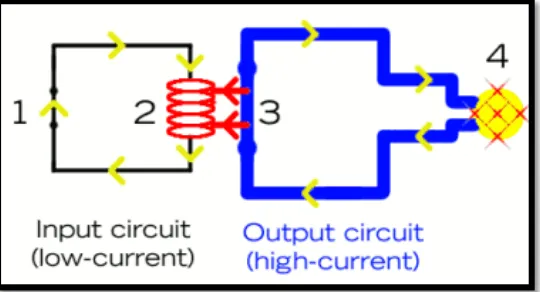
Figure 2.4: Relay
Relay can be defined as an electrically operated switch that can turn on or off a much larger electric current. Mainly there are two principles used by relay which is electromagnetic and solid-state relay. Electromagnetic principles is used to operate a switch meanwhile solid-state relays control power circuits with no moving parts, instead using a semiconductor device to perform switching. Figure and explanation below show how relay work is.
7
until something (either a sensor or a switch closing) turns it on. The output circuit (blue loop) is also switched off.
2. When a small current flows in the input circuit, it activates the electromagnet (shown here as a red coil), which produces a magnetic field all around it.
3. The energized electromagnet pulls the metal bar in the output circuit toward it, closing the switch and allowing a much bigger current to flow through the output circuit.
4. The output circuit operates a high-current appliance such as a lamp or an electric motor.
2.4: RFID (Radio Frequency Identification)
According to Vangie Beal, RFID is a technology similar in theory to bar code identification. With RFID, the electromagnetic or electrostatic coupling in the RF portion of the electromagnetic spectrum is used to transmit signals. RFID systems consists of an antenna and a transceiver, which read the radio frequency and transfer the information to a processing device, and a transponder, or tag, which is an integrated circuit containing the RF circuitry and information to be transmitted. RFID systems can be used just about anywhere, from clothing tags to missiles to pet tags to food -- anywhere that a unique identification system is needed. High frequency RFID systems (850 MHz to 950 MHz and 2.4 GHz to 2.5 GHz) offer transmission ranges of more than 90 feet, although wavelengths in the 2.4 GHz range are absorbed by water (the human body) and therefore has limitations.
2.4.1: Component of the RFID System
8
and data is exchanged when the tag come in proximity ti the reader signal. Tags can be categorized as follow:
1. Active tags, which has a battery that supplies power to all functions
2. Semipassive tags, which has a battery used only to power the tag IC not for communication
3. Passive tags, which has no battery on it. The absence of power supply makes passive tags much cheaper and more reliable than active tags.
2.4.1.1: Active Tags Description
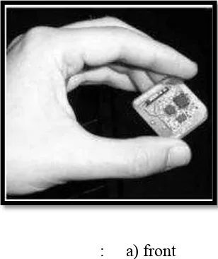
An active tag usually performs a specialized task and has an on-board power source (usually battery). It does not require induction to provide current, as is true of the passive tags. The active tags can be designed with a variety of specialized electronic including microprocessor, different types of sensors or I/O devices. They are larger and more expansive than passive tags, but can hold more data about the product and are commonly used for high-value asset tracking.
: a) front b) reverse sides
Figure 2.6: Active tags
2.4.1.2: Passive Tags Description
9
significantly closer than an active one would. Uses of passive tags tend to include things such as inventory, product shipping and tracking, where it is practical to have reader within a few meters or so of the RFID device.
Figure 2.7: Passive Tags
2.5: RFID APPLICATION
10
2.5.1: STUDIES ON USAGE OF RFID AND ARDUINO
2.5.1.1: RFID Becomes an Overnight Sensation for Sernam
Sernam is French shipping and logistics company which have been operate since 2001. The purpose of using RFID in their company is for improve its operations competitiveness and capabilities. Sernam has been applying RFID tags to all parcels it collect and ships overnight. In this case, that parcels will then tracking them as they pass through Sernam’s Paris distribution center. Therefore, by adding RFID it creates a trail of each tagged parcels movement trough the company operations at once increases their operation efficiency and bring greater value to their customer.
According to Gwennaelle Perron, who is responsible for traceability solutions at Sernam, adding RFID makes it easier for they to handle parcels, and they expect at least one less staff member will be required to track shipments in and out of the DC, compared to our current bar-code system. At that time, one of Sernam's publishing customers applies RFID-enabled labels to its parcels. The labels are also printed with bar codes, still used both as a backup for the RFID system during the trial, and for points in the delivery chain at which that customer does not yet use RFID for such things as pick-up and delivery.