UNIVERSITI TEKNIKAL MALAYSIA MELAKA
CONCEPTUAL DESIGN AND PERFORMANCE ANALYSIS OF
THE AIR MOTOR FOR AIR POWERED MOTORCYCLE
This report submitted in accordance with requirement of the Universiti Teknikal Malaysia Melaka (UTeM) for the Bachelor Degree of Mechanical Engineering
Technology (Automotive Technology) (Hons.)
by
MUHAMMAD NORSYAFIQ BIN MD NASIB B071110192
920211-14-6651
UNIVERSITI TEKNIKAL MALAYSIA MELAKA
BORANG PENGESAHAN STATUS LAPORAN PROJEK SARJANA MUDA
TAJUK: Conceptual design and performance analysis of the air motor for air powered motorcycle
SESI PENGAJIAN: 2014/15 Semester 1
Saya MUHAMMAD NORSYAFIQ BIN MD NASIB
mengaku membenarkan Laporan PSM ini disimpan di Perpustakaan Universiti Teknikal Malaysia Melaka (UTeM) dengan syarat-syarat kegunaan seperti berikut: 1. Laporan PSM adalah hak milik Universiti Teknikal Malaysia Melaka dan penulis. 2. Perpustakaan Universiti Teknikal Malaysia Melaka dibenarkan membuat salinan
untuk tujuan pengajian sahaja dengan izin penulis.
3. Perpustakaan dibenarkan membuat salinan laporan PSM ini sebagai bahan pertukaran antara institusi pengajian tinggi. atau kepentingan Malaysia sebagaimana yang termaktub dalam AKTA RAHSIA RASMI 1972)
(Mengandungi maklumat TERHAD yang telah ditentukan oleh organisasi/badan di mana penyelidikan dijalankan)
Alamat Tetap:
NO. 8 Jalan Anggerik 1I/1 Taman Desa Anggerik
iv
DECLARATION
I hereby, declared this report entitled “Conceptual Design and Performance Analysis of the Air Motor for Air Powered Motorcycle” is the results of my own
research except as cited in references.
Signature :
Author’s Name : Muhammad NorSyafiq Bin Md Nasib
v
APPROVAL
This report is submitted to the Faculty of Engineering Technology of UTeM as a partial fulfillment of the requirements for the degree of Bachelor of Engineering Technology (Automotive Technology) (Hons.). The member of the supervisory is as follow:
vi
ABSTRAK
vii
ABSTRACT
viii
DEDICATION
ix
ACKNOWLEDGEMENT
In the name of Allah, the Most Merciful and the Most Beneficent. It is with the deepest senses gratitude of the almighty that gives strength and ability to complete the project for this semester based on the project planning
First of all, I would like to dedicate my special thanks to my supervisor, En Nor Azazi Bin Ngatiman and also to my co-supervisor, Cik Hamizah Binti Miswan for allowing me to do this project under his supervision. Thanks again for giving me all the valuable information and ideas on how to perform this project.
xi
2.6.2 Air Pressure Gauge and Regulator 24
2.6.3 Air Flow Rate Control Valve 24
CHAPTER 3: METHODOLOGY 29
3.1 Introduction 29
3.2 Process Flow 29
3.2.1 Flow Chart 30
3.3 Process Briefing 31
3.3.1 Engineering Characteristic 31
3.3.2 Sketching the Air Motor Design 32
3.3.3 Selected the Best Design 34
3.3.4 Focusing on the Vane Motor Concept 34
3.3.5 Identified Parameter of the Vane Motor 35
3.3.6 Calculated the Performance of Vane Motor 36 3.3.7 Drawing the Conceptual Design using CATIA Software 39
CHAPTER 4: RESULT AND DISCUSSION 40
4.1 Data and Input Parameters 40
4.2 Result Calculation for Vane Motor 42
xii 4.3 Discussion based on Data and Result Calculation 79
4.3.1 Discussion based on Ratio Diameter Vane Motor 0.95 79 4.3.2 Discussion based on Ratio Diameter Vane Motor 0.90 80 4.3.3 Discussion based on Ratio Diameter Vane Motor 0.85 81 4.3.4 Discussion based on Ratio Diameter Vane Motor 0.80 82 4.3.5 Discussion based on Ratio Diameter Vane Motor 0.75 83 4.3.6 Discussion based on Ratio Diameter Vane Motor 0.70 84 4.3.7 Discussion based on Ratio Diameter Vane Motor 0.65 85 4.3.8 Discussion based on Ratio Diameter Vane Motor 0.60 86 4.3.9 Discussion based on Ratio Diameter Vane Motor 0.55 87
4.4 Conclusion for Calculation Vane Motor 88
4.5 Conceptual Design of the Vane Motor 89
CHAPTER 5: CONCLUSION AND FUTURE WORK 91
5.1 Conclusion 92 5.2 Recommendation 92 REFERENCE 93 APPENDIX 95
xiii
LIST OF TABLES
2.1 Specification of the modified 2-stroke engine operation 14
2.2 Input parameters 21
3.1 Engineering characteristic and sub-function 31
3.2 Data input and parameters of vane motor 35
4.1 Data and input parameters for the vane motor 41
4.2 Input parameter with ratio diameter vane motor is 0.95 42 4.3 Data when the ratio diameter of vane motor is 0.95 45 4.4 Input parameter with ratio diameter vane motor is 0.90 46 4.5 Data when the ratio diameter of vane motor is 0.90 49 4.6 Input parameter with ratio diameter vane motor is 0.85 50 4.7 Data when the ratio diameter of vane motor is 0.85 53 4.8 Input parameter with ratio diameter vane motor is 0.80 54 4.9 Data when the ratio diameter of vane motor is 0.80 57 4.10 Input parameter with ratio diameter vane motor is 0.75 58 4.11 Data when the ratio diameter of vane motor is 0.75 61 4.12 Input parameter with ratio diameter vane motor is 0.70 62 4.13 Data when the ratio diameter of vane motor is 0.70 66 4.14 Input parameter with ratio diameter vane motor is 0.65 67 4.15 Data when the ratio diameter of vane motor is 0.65 70 4.16 Input parameter with ratio diameter vane motor is 0.60 71 4.17 Data when the ratio diameter of vane motor is 0.60 74 4.18 Input parameter with ratio diameter vane motor is 0.55 75 4.19 Data when the ratio diameter of vane motor is 0.55 78
xiv
LIST OF FIGURES
2.1 Flow chart for literature review 5
2.2 Compressed Air Vehicle usage at 18th century 6
2.3 Model of Air Compressed Vehicle by Tata Motor 7
2.4 Vane Motor 10
2.5 Air Rotary Engine 12
2.6 Radial Air Piston 13
2.7 The movement of cylinder pressure, inlet and outlet pressure, 15 torque and valve lift in complete cycle of modified air engine
2.8 Graph of power versus rotation speed and pressure 16
2.9 Compressed Air Engine 17
2.10 Liquid Air Engine 17
2.11 T-S diagram of Compressed Air Engine 18
2.12 T-S diagram of Liquid Air Engine 18
2.13 Multivane Air Engine Model 20
2.14 Graph of expansion power versus ratio rotor and casing 22
2.15 Example of Air Receiver 23
2.21 Component of Air Rotary Engine 28
xv
4.1 Diagram of sketch for the Vane Motor 41
4.2 Graph of total power (kW) versus angle between vane (ɵ)/number 79 of vane for ratio 0.95
4.3 Graph of total power (kW) versus angle between vane (ɵ)/number 80 of vane for ratio 0.90
4.9 Graph of total power (kW) versus angle between vane (ɵ)/number 86 of vane for ratio 0.60
4.10 Graph of total power (kW) versus angle between vane (ɵ)/number 87 of vane for ratio 0.55
xvi
CATIA - Computer Aided Three-Dimensional Interactive Application
D - Diameter of Stator
Ө - Degree of Angle between Nozzle Inlet and Rotor
1
1.1 Background
In recent years there has been increasing air pollution due to several factors, where the sources of air pollution come out in two types of source which are sourced from vehicle and source from the factory. This two type source can be categories as a major source for the air pollution. The vehicle sources include the forms of transportation such as on cars and trucks, as well as non road vehicle such as tractors, backhoes, trains, and airplanes. While, the factory sources are consist power plants, industrial facilities, gas stations, or construction site.
There are many systems have been developed by the federal government to counter and minimize the air pollution. Example controls the emission produce in factory by creating the filter to reduce the exposed chemical reaction on the air. While in the vehicle, use gasoline without lead to reduce emissions and develop an engine system that can minimize the emissions during it moving.
2 The emission comes from the vehicle often caused by incomplete combustion in internal combustion engine that will produce the nitrogen oxide, hydrocarbon and carbon dioxide. This condition occur cause of the failure of engine systems and until now this problem cannot be solved due to the lack of advanced tools and technologies in this country.
Today the air powered motor is a new advancement technology design in the automotive field that used the pure compressed air as the main source to operate the engine system. This new design was developed in order to reduce the emission level to save the world. Besides that, it can also eliminate the cost of gasoline and this current technology has been developed to be used especially for light compact vehicle.
Although the air powered motor has been left in this world since the 19th century ago, this technology is still not suitable in the automotive field because there it performance is still no match for existing technologies such as hybrid engines and electric vehicle.
1.2 Project Title
Conceptual design and performance analysis of the air motor for air powered motorcycle
1.3 Problem Statement
3
1.4 Project Objective
I. To study the concept of air motor system for air powered motorcycle. II. To analyze the power output of air motor based on numerical.
III. To drawing conceptual design of air motor for an air powered motorcycle.
1.5 Project Scope
I. Study the concept of air motor system based on previous research and references.
II. To investigate the relation of the power output that the air motor provides based on numerical and experimental result.
4
2.1 Introduction of the Compressed Air Vehicle
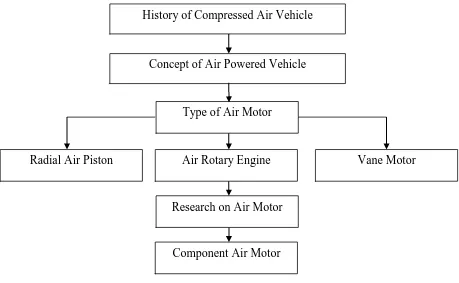
This chapter is divided into several sections. The first two sections are described about a history and concept of compressed air vehicle. Type of air motor will be discussed later in the following section. There are three types of air motor have been focused which are vane motor, air rotary engine and radial air piston. Next is a previous research of the related study. The main components of air motor and the description will be explained after previous research section. The structure organization of the literature review is described as shown in Figure 2.1.
5 Figure 2.1: Flow chart for literature review
2.2 History of Compressed Air Vehicle
The compressed air vehicle is not a new vehicle in recent technology that exists in this world because it has been used since the 19th century. Denis Papen was among the earliest published ideas for the use of compressed air to locomotive pneumatics usage. In 1838, Andraud and Tessie from Motay, France have successfully to produce a compressed air vehicle and the result is the vehicle capable running and work out so well. Unfortunately an idea for improvements in the vehicle was not pursued at that time. (Manish, 2012)
History of Compressed Air Vehicle
Concept of Air Powered Vehicle
Type of Air Motor
Air Rotary Engine Vane Motor
Radial Air Piston
Research on Air Motor
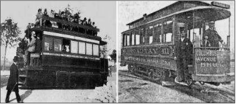
6 In 1872, the emergence Mekarsari Air Engine Thermodynamic concept had been developed for the locomotive and its impact the use of this engine have been growing and used exclusively for road transit until 1879.Besides that, this vehicle was sold directly with large quantity to the coal mines in the United States. The design and energy produced by this vehicle can be categorized type vehicle suitable and safe for the mining of coal and gaseous are main factor this vehicle has value. Furthermore, the vehicle was created without generated heat energy and sparks to running. (Manish, 2012)
Figure 2.2: Compressed Air Vehicle usage at 18th century (Thipse, 2008)
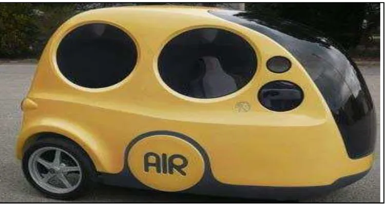
7 Unfortunately, the compressed air vehicle used the same concept and the development on it does not continue until the 20th century. In the early 20th century, the compressed air vehicle has come with new technology where this advancement was formed by Formula One engineer, Guy Negre. He was developed Motor Development International (MDI) and also cooperated with the other companies to develop the design of an air powered vehicle shown as Figure 2.3. The MDI and Indian car manufacturing, Tata Motor have signed deals to produce and marketing for the MDI air powered vehicle, while the MDI only focuses on the advancement of the air powered vehicle. (Andrew et.al, 2010)
8
2.3 Understanding the Concept of Compressed Air Vehicle
The air compressed vehicle work by using high pressurized air to convert the energy compressed air into mechanical energy o powered the vehicle. The principles operational of air compressed vehicle produce zero emission level compared to the other engine. (Yu-Ta Shen and Yean-Ren Hwang, 2009)
The operation system of the compressed air vehicle is start with receives high pressurized air from the storage tank located inside a vehicle. The high pressurized air will slowly powered the mechanical part inside air motor. The function of the air motor is to convert the adiabatic and isobaric expansion of pressure into the mechanical energy. These powers were transmit to the wheels. (Baggott and Mullen, 2012)
There are two methods that can be used to collect compressed air in its storage tank. The first method is the vehicle used advanced components such as electrically injected directly supply compressed air into the tank and the second method is by plugging the car into a wall outlet of vehicle. (Strumpf et.al, 2009). The energy storage of compressed air vehicle is mostly similar with an electric storage. (Papson et.al, 2010)
The storage tank is function to maintain the pressurize air and supply it to the air motor by using hose as a connection between these two component. The pressurize air inside the air motor move the rotor or mechanical part inside air motor and it directly transmit the power to the wheel. The 90 percent claim that design of the air compressed system can affect the performance of the air motor. (Bonser, 2008)
9 The exhaust temperature that comes out from air compressed vehicle was less than atmospheric temperature and this situation is mostly helping in controlling global warming and reducing temperature rise. The design for this air motor also helps in reducing wear and tear at it component because there are no combustion inside the cylinder and, material that used in air motor are mostly self-lubricating and the working temperature of air motor are less than normal temperature atmosphere. Thus, this air motor does not require installing the cooling and lubricating system. (Patel et.al. 2001). The energy produces from compressed air vehicle is less compared to the other energy such as energy produce hybrid engine, electrical motor and combustion internal engine. (Schipper, 2010)
2.4 Type of Air Motor