UNIVERSITI TEKNIKAL MALAYSIA MELAKA
CUTTING TECHNOLOGY AND SINTERING JIG
DEVELOPMENT FOR MANUFACTURING OF
HOLLOW STRUCTURE MAT
This report submitted in accordance with requirement of the Universiti Teknikal Malaysia Melaka (UTeM) for the Bachelor Degree of Manufacturing Engineering
(Manufacturing Process) (Hons.)
by
MOHD DZAHIR BIN HAJI ABDUL HALIM B051110352
890129-43-5177
UNIVERSITI TEKNIKAL MALAYSIA MELAKA
BORANG PENGESAHAN STATUS LAPORAN PROJEK SARJANA MUDA
TAJUK: Cutting Technology and Sintering Jig Development for Manufacturing of Hollow Structure Mat
SESI PENGAJIAN: 2014/15 Semester 2
Saya MOHD DZAHIR BIN HAJI ABDUL HALIM
mengaku membenarkan Laporan PSM ini disimpan di Perpustakaan Universiti Teknikal Malaysia Melaka (UTeM) dengan syarat-syarat kegunaan seperti berikut: 1. Laporan PSM adalah hak milik Universiti Teknikal Malaysia Melaka dan penulis. 2. Perpustakaan Universiti Teknikal Malaysia Melaka dibenarkan membuat salinan
untuk tujuan pengajian sahaja dengan izin penulis.
3. Perpustakaan dibenarkan membuat salinan laporan PSM ini sebagai bahan pertukaran antara institusi pengajian tinggi.
4. **Sila tandakan ( )
SULIT
TERHAD
TIDAK TERHAD
(Mengandungi maklumat yang berdarjah keselamatan atau kepentingan Malaysia sebagaimana yang termaktub dalam AKTA RAHSIA RASMI 1972)
(Mengandungi maklumat TERHAD yang telah ditentukan oleh organisasi/badan di mana penyelidikan dijalankan)
Alamat Tetap:
68, Jalan Sri Siantan 49,
Taman Sri Andalas, 41200 Klang, Selangor Darul Ehsan.
Tarikh: ________________________
Disahkan oleh:
Cop Rasmi:
Tarikh: _______________________
DECLARATION
I hereby, declared this report entitled “Cutting Technology and Sintering Jig Development for Manufacturing of Hollow Structure Mat” is the results of my own
research except as cited in references.
Signature : ………..
Author’s Name : MOHD DZAHIR BIN HAJI ABDUL HALIM
APPROVAL
This report is submitted to the Faculty of Manufacturing Engineering of UTeM as a partial fulfillment of the requirements for the degree of Bachelor of Manufacturing Engineering (Manufacturing Process) (Hons.). The member of the supervisory is as follow:
i
ABSTRAK
ii
ABSTRACT
iii
DEDICATION
iv
ACKNOWLEDGEMENT
First and foremost, I would like to express my highest appreciation to my supportive academic supervisor, Dr. Hadzley B. Abu Bakar. His supervision and support that gave me truly helps during the period of conducting my thesis. His never-ending supply of valuable advice and guidance has enlightened me and deeply engraved in my mind.
Next, I would like to dedicate my thankfulness to machinery laboratory technicians, who has been so warmth and kind to provide sincere assistance and good cooperation during the training period. Their co-operation is much indeed appreciated. In addition, I would like to thank to FKP lecturers, for their assistance, which really spends their time to teach me a lot of knowledge regarding the design development.
v 2.2.1.5 AC Induction Motor Application and Operation 8
2.2.2 Gear System 9
2.2.2.1 Type of Gear 10
2.2.3 Belting System (V-Belt) 15
2.2.3.1 Basics 15
vi
2.2.3.3 V-Belt Analysis 17
2.2.3.4 Belt Tension 18
2.2.4 Pulley System 19
2.2.5 Bearings 21
2.2.5.1 Classification and Operation of Bearings 21 2.2.5.2 Rolling Element-type Bearing 23
2.2.6 Shaft 27
2.2.7 Bandsaw Blade 28
2.3 Jigs and Fixtures 28
2.3.1 Application and Classification of Jigs and Fixtures 31
2.4 Location 32
3.3.1.1 Design of Vertical Bandsaw Machine 36
3.3.1.2 Design of Sintering Jig 40
3.3.7 Suggestion for Simplification of Product 43
3.3.8 Identification Process 43
3.3.9 Detail Design for Minimum Manufacturing Cost 43
3.3.10 Production 43
3.4 Pugh Method 43
vii 3.5 Component Selection for Vertical Bandsaw Machine 46 3.5.1 Electric Motor (Induction Motor) 46
3.5.2 Gear (Spur Gear) 47
3.5.3 Bearing (Ball Bearing) 47
3.5.3 Belting System (V-Belt) 48
3.6 Manufacturing Process Selection 48
3.6.1 Machining Process 48
4.1.2 Assembly of Vertical Bandsaw Machine 53 4.2 Development of Sintering Jig 55
4.2.1 Fabrication Process of Body Frame 55
4.2.2 Fabrication Process of Jig Clamp 58
4.2.3 Joining Process of Jig Wheels 60
4.3 Analysis on Vertical Bandsaw Machine 61 4.3.1 Test Cutting 61
4.3.2 Burr Formation 63 4.3.3 Cutting by Using Handsaw 63
viii
REFERENCES 69
APPENDICES
ix
Classification of Manual Work Fixtures
Pugh method table for Vertical Bandsaw Machine Pugh method table for Sintering Jig
Manufacturing Process for Vertical Bandsaw Machine Manufacturing Process for Sintering Jig
Assembly process of Vertical Bandsaw Machine
x
Illustration of Hollow Structure Mat 2
AC Motor 7
Single-phase AC Power 8
Three-phase AC Power 8
Squirrel-Cage Induction Rotor 9
Gear Tooth Parts 10
Simple Pulley System 20
Pulley Wheel 20
Pulley Wheel with Keyed Shaft 20
An Installation of a Ball Bearing 22
Pillow Block Bearing 22
Elements of a standard ball bearing 23
Point contact in ball bearing 24
Line contact in straight roller bearing 24 Structure of a straight roller bearing 25
Tapered Roller Bearing 26
Structure of Thrust Roller Bearing 26
xi
Swage and Spring Tooth Set 28
Flow Chart of Project Planning 35
Design Concept 1 of Vertical Bandsaw Machine 37 37 Design Concept 2 of Vertical Bandsaw Machine 38
Design Concept 3 of Vertical Bandsaw Machine 39
Design Concept 1 of Sintering Jig 40
Design Concept 2 of Sintering Jig 41
Design Concept 2 of Sintering Jig 41
Cutting process of main bar 52
Drilling process 52 52
Measuring process 56
Cutting process of raw material 56 56
Metal inert-gas (MIG) welding equipment 57 The frame alignment and stability check 57
Clamp locator 59
Threaded screw 59
Steel rod handles 60
Wheel with a lock function 60
The jig for clamping 61
The hollow structure mat is clamped by using a long F-clamps 61
Cutting process 62
Feeding direction during cutting process 62
Cut by handsaw 63
Cut by bandsaw 64
Jig placed in a sintering chamber 66
xii
LIST OF ABBREVIATIONS, SYMBOLS AND
NOMENCLATURE
AC - Alternate Current DC - Direct Current
HP - Horse Power
Hz - Hertz
PP - Polypropylene
1
1.1 Background of project
The plastics and plastics products industry is one of the most dynamic and vibrant growth sectors within the Malaysian manufacturing sector. The Malaysian plastics industry has developed into a highly diversified sector producing an array of products including automotive components, electrical and electronic parts, construction materials, household goods, bottles, containers, toys, games and packaging materials. One of the plastic application is in the constructing of a structural support mat for load. The process that involves in the production of hollow structure mat is the sintering process. The sintering process is conducted in the large sintering chamber. Therefore, a special jig and clamping mechanism are needed in order to hold and press the customized plastic in the sintering chamber.
The main function of jig is to hold, locate and support the workpiece for the various types of machining. A jig's primary purpose is to provide repeatability, accuracy, and interchangeability in the manufacturing of products. Usually, the jig is used for the operation of small parts. The special jig is needed to hold and press the plastic due to the large dimension of the product. The sintering process will be done by Department of Civil Engineering at the University Tun Hussein Onn Malaysia.
INTRODUCTION
2 After the plastic is sintered, it must be cut into various sizes for the structural support platform. Usually, a plastic is cut by using laser cutting machine, however, it is only ideals for the thin part dimension because the thickness of material can affect the cutting quality. The vertical bandsaw machine is the most suitable machine to cut the large dimension of plastic with the minimum cost required.
1.2 Problem Statement
The hollow structure mat is produced by using a plastic. The material of the plastic comes in a tubular shape with a length of 1 meter, which will be sintered to create a dimension of 1m x 1m x 1m as shown in Figure 1.1. The structured of the hollow structure mat is honeycomb structure. In order to have a good joining between each plastic, it must be press uniformly during the sintering process. Therefore, a special jig and clamping mechanism are needed to hold and press the plastic to produce a structural mat.
Figure 1.1: Illustration of Hollow Structure Mat
3
1.3 Objectives
The main objective of this research is:
i. To develop a vertical bandsaw machine for cutting process of hollow structure mat.
ii. To fabricate a sintering jig for sintering process of hollow structure mat.
1.4 Scope of Project
4
2.1 Existing Product
Nowadays, users emphasize on the management of time, space for storage, safety and energy that need to do the work. Existing machine uses as example for research and to develop improvement based on user requirement. There are some products or machine that existing now in order to cut material but cannot cut big material.
2.2 Component of Vertical Bandsaw Machine
2.2.1 Electric Motor
A motor is nothing but an electro-mechanical device that converts electrical energy to mechanical energy. An electric motor is the most important part in the machine, especially for the vertical bandsaw machine. The main function of an electric motor in bandsaw machine is to rotate the bandsaw blade which is attached to the wheels. The blade must suitable to the bandsaw application so that the material being cut has a good surface properties. Besides that, the determination of electric motor also important in order to reduce the machining time, production cost and labor cost.
LITERATURE REVIEW
5
2.2.1.1Motor Type
The motor-type classification on the information plate eludes to the kind of ventilation the engine employments. One sort is open sort, which gives course through ventilation from the fan mounted on the end of the rotor. In a few motor that are appraised for variable-speed obligation (utilized with variable-recurrence drives), the fan is particular motor that is incorporated with the end of the rotor. The fan motor is joined straightforwardly over the supply voltage, so it will keep up a consistent speed to give steady cooling paying little respect to the motor speed.
An alternate type of motor is the encased type. The encased motor is not air-cooled with a fan; rather it is made to permit high temperature to disseminate rapidly to and from within the motor outward of the edge. As a rule the edge has fins based into it on the outside to give more zones to cooling air to reach. (Kissell, 1999)
2.2.1.2Motor Selection Factors
According to Mott (1999), as a minimum, the following items must be specified for motors:
i. Motor type: DC, AC, single-phase, three-phase and so on. ii. Power rating and speed.
6
Operation torque, operating speed and power rating. Note that these are related by the equation:
Power = torque x speed
Starting torque.
Load variations expected and corresponding speed variations that can be tolerated.
Current limitations during the running and starting phase operation.
Duty cycle: how frequently the motor is to be started and stopped.
Environmental factors: temperature, presence of corrosive or explosive atmospheres, exposure to weather or to liquids, availability of cooling air and so on.
Voltage variations expected: most motors will tolerate up to (+-10%) variation from the rated voltage. Beyond this, special designs are required.
Shaft loading, particularly side loads and thrust loads which can affect the life of the shaft bearings.
2.2.1.3Motor Size
A rough classification of motors by size is used to group motors of similar design. Horse-power (hp) is currently used most frequently, with the metric unit of watts or kilowatts also used at times. The conversion is:
1.0 hp = 0.746kW = 746 W
The classifications are as follows:
Subfractional horsepower: 1 to 40 milihorsepower (mhp), where 1mhp = 0.001hp, thus, this range includes 0.001 to 0.040 hp (0.75 to 30 W approximately).
Fractional horsepower: 1/20 to 1.0 hp (37 to 746 W, approximately).
7
2.2.1.4AC Motor and General Information of AC Power
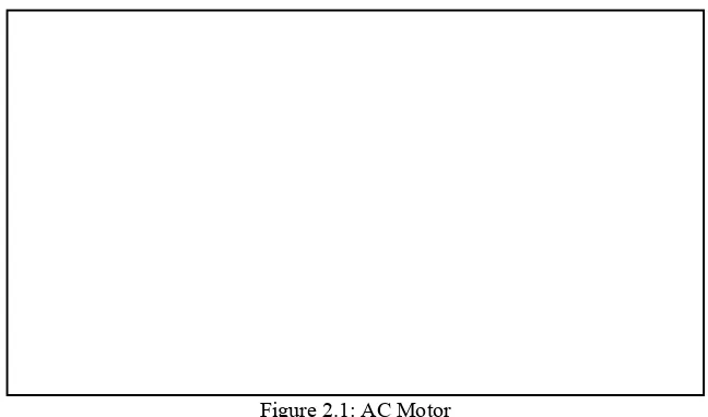
Alternating current (AC) motors utilize an electrical current, which reverses its direction at regular intervals. An AC motor has two basic electrical components, a 'stator' and a 'rotor' as depicted in Figure 2.1. The stator is in the stationary electrical component. The rotor is the rotating electrical component, which in turn rotates the motor shaft.
Figure 2.1: AC Motor
(Source: http://www.jconsultingonline.com)
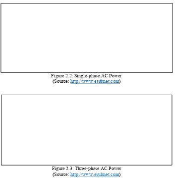
8 Figure 2.2: Single-phase AC Power
(Source: http://www.esubnet.com)
Figure 2.3: Three-phase AC Power (Source: http://www.esubnet.com)
2.2.1.5AC Induction Motor Application and Operation
The AC induction motor is the most commonly used AC motor in industrial applications because of its simplicity, rugged construction, and relatively low manufacturing costs. The reason that the AC induction motor has these characteristics is because the rotor is a self-contained unit, with no external connections. This type of motor derives its name from the fact that AC currents are induced into the rotor by a rotating magnetic field. The AC induction motor's rotor as shown in Figure 2.4 is made of a laminated cylinder with slots in its surface. The windings in the slots are one of two types.