UNIVERSITI TEKNIKAL MALAYSIA MELAKA
DESIGN OF REMOTELY UNDERWATER VEHICLE (ROV)
USING EMBEDDED SYSTEM
This report is submitted in accordance with the requirement of Universiti Teknikal Malaysia Melaka (UTeM) for the Bachelor of Electrical Engineering Technology
(Industrial Automation and Robotics) with Honours
by
MOHAMMAD ADIB BIN SALIKON
B071210234
911008 - 01 - 7075
UNIVERSITI TEKNIKAL MALAYSIA MELAKA
BORANG PENGESAHAN STATUS LAPORAN PROJEK SARJANA MUDA
TAJUK: Design of Remotely Underwater Vehicle(ROV)Using Embedded System
SESI PENGAJIAN: 2014/15 Semester 2
Saya MOHAMMAD ADIB BIN SALIKON
Mengaku membenarkan Laporan PSM ini disimpan di Perpustakaan Universiti Teknikal Malaysia Melaka (UTeM) dengan syarat-syarat kegunaan seperti berikut:
1. Laporan PSM adalah hak milik Universiti Teknikal Malaysia Melaka dan penulis. 2. Perpustakaan Universiti Teknikal Malaysia Melaka dibenarkan membuat salinan
untuk tujuan pengajian sahaja dengan izin penulis.
3. Perpustakaan dibenarkan membuat salinan laporan PSM ini sebagai bahan pertukaran antara institusi pengajian tinggi.
4. **Silatandakan ( )
SULIT
TERHAD
TIDAK TERHAD
(Mengandungi maklumat yang berdarjah keselamatan atau kepentingan Malaysia sebagaimana yang termaktub dalam AKTA RAHSIA RASMI 1972)
(Mengandungi maklumat TERHAD yang telah ditentukan oleh organisasi/badan di mana penyelidikan dijalankan)
(___________________)
Alamat Tetap:
Pos 3, Lrg 4, Kg Seri Telok, Parit Yaani, 83710 Yong Peng,
Batu Pahat, Johor.
Disahkan oleh:
(__________________)
Cop Rasmi:
iii
DECLARATION
I hereby, declared this report entitled “Design of Remotely Underwater Vehicle (ROV) Using Embedded System” is the results of my own research except as cited in
references.
Signature: ___________________
Author: Mohammad Adib Bin Salikon
iv
APPROVAL
This report is submitted to the Faculty of Engineering Technology of UTeM as a partial fulfillment of the requirements for the degree of Bachelor of Electrical Engineering Technology (Industrial Automation and Robotics) with Honours. The member of the supervisory is as follow:
……….
v
ABSTRACT
vi
ABSTRAK
vii
DEDICATIONS
viii
ACKNOWLEDGMENTS
Firstly, Praise to Allah who‟s gives me strength for completing my PSM to
building Remotely Underwater vehicle (ROV). Secondly, thank you to my supervisors which is MR.RAZALI BIN MOHAMAD SAPIEE and MR.MOHD ZAIDI BIN MOHD TUMARI who‟s gives me a lot of study and monitoring me to
do this project. Thirdly, a lot of thank you to my beloved parent, siblings and friends who‟s give me moral support, motivation and also help me to complete this project.
ix
2.2 Communication Medium ... 4
2.3 Thruster and Motor ... 5
x
CHAPTER 3 ... 11
3.0 Introduction ... 11
3.1 Work flow ... 12
3.2 ROV structure design review ... 13
3.2.1 ROV mechanical component ... 14
3.3 Electrical Hardware Review ... 14
3.3.1 Arduino Mega Board... 15
3.3.2 Bluetooth Device HC-06 ... 15
3.3.3 L298N Motor Driver ... 17
3.4 Software Review ... 17
3.5 System Development ... 19
3.5.1 MIT Inverter 2.0 Software for Creating mobile apps ... 19
3.5.2 Creating command block in MIT Inverter ... 22
3.5.3 Compiling Designer and Block as APK format ... 24
3.5.4 Arduino 1.6.3 Software for programming ... 25
3.5.5 SolidWorks 2013 Software for design ROV model ... 27
3.5.6 Converting SolidWorks Part(.SLDPRT) to STL format ... 34
3.6 Mechanical Development ... 34
3.6.1 Electrical Installation ... 34
3.6.1.1Power supply separation ... 35
3.6.1.2Distribution of Input and Output from Arduino Board ... 36
3.6.1.3Distribution Motor Driver Output ... 37
xi
3.6.2.1Build Part using 3D Printing ... 38
3.6.2.2Combining 3D part with order stuff ... 43
3.7 Calculating Ideal ROV weight ... 47
CHAPTER 4 ... 49
4.0 Introduction ... 49
4.1 ROV Buoyancy ... 50
4.2 Communication ... 50
4.3 ROV diving ability ... 52
CHAPTER 5 ... 54
5.0 Introduction ... 54
5.1 Summary of Research ... 54
5.2 Achievement of Research Objectives ... 54
5.3 Significance of Research ... 55
5.4 Problems Faced During Research ... 55
5.5 Suggestion for Future Work ... 55
APPENDIX A ... 56
APPENDIX B ... 61
xii
LIST OF FIGURES
Figure 2.1 : Optical Cable ... 5
Figure 2.2: RS232 cable ... 6
Figure 2.3: Micro-strip antenna ... 6
Figure 2.4 : Thruster configuration place ... 7
Figure 2.5: Motor housing ... 6
Figure 2.5: Buoyancy ... 9
Figure 2.6: Solid body condition when drop into the water. ... 9
Figure 2.7: Archimedes‟s principle ... 10
Figure 2.8 „G‟ is centre gravity and „B‟ is centre of buoyancy... 11
Figure 2.9: Stability concept used for the ship. ... 11
Figure 2.10: Submarine concept ... 12
Figure 3.1: Work flow ROV development ... 14
Figure 3.2: ROV back view. ... 15
Figure 3.3: Thruster ... 16
Figure 3.4: Arduino Mega Board 2560 ... 17
Figure 3.5: Bluetooth devices. ... 18
Figure 3.6: L298 motor driver board... 19
Figure 3.7: Home layout ... 20
Figure 3.8: Control layout (diving mode). ... 21
Figure 3.9: MIT inverter web software. ... 22
Figure 3.10: Flow chart Mobile applications. ... 23
Figure 3.11: Screen1 ... 24
Figure 3.12: Screen2 ... 24
Figure 3.13: ROV mobile application command blocks. ... 25
Figures 3.14: Compiling process.. ... 26
Figures 3.15: Arduino 1.6.3 software... 27
Figure 3.16: Flow chart of programming flow... 28
Figure 3.17: Servo command. ... 29
Figure 3.18: SolidWorks 2013 ... 30
Figure 3.19: Left and right part ... 30
Figure 3.20: Bottom part.. ... 31
Figure 3.21: Servo Part.. ... 32
Figure 3.22: Rudder part. ... 33
Figure 3.23: Thrusters holder. ... 34
Figure 3.24: Full assemble of all part... 35
Figure 3.25: STL converted process. ... 36
Figure 3.26: Electrical installation block diagram. ... 37
Figure 3.27: Lipo battery... 38
xiii
Figure 3.29: Pin connection ... 39
Figure 3.30: Motor driver connection. ... 39
Figure 3.31: 3D printer machine... ... 40
Figure 3.32: Front view and back view of printer ... 41
Figure 3.33: Placing Perfboard. ... 41
Figure 3.34: Nozzle preheating process. ... 42
Figure 3.35: ABS material out from the nozzle. ... 42
Figure 3.36: Part1_holder.stl and Part2_holder.stl... 43
Figure 3.37: Print setup windows. ... 43
Figure 3.38: Information windows. ... 44
Figure 3.39: Part1_holder is printed... 44
Figure 3.40: Rudder part is printed. ... 47
Figure 3.41: Top view ... 47
Figure 3.42: Side view. ... 47
Figure 3.43: Bottom view.. ... 47
Figure 3.44: Back view ... 48
Figure 3.45: Front view.. ... 48
Figure 3.46: 80 gallon water tank.. ... 49
Figure 4.1: ROV sinking 1”inch from the surface ... 52
Figure 4.2: Bluetooth distance against time. ... 51
Figure 4.3: 7500 rpm downward speed against time ... 53
Figure 4.4: 15000 rpm downward speed against time ... 53
Figure 4.5: 7500 rpm upward speed against time. ... 54
Figure 4.6: 15000 rpm upward speed against time ... 54
Figure 4.6: Forward thruster against time. ... 54
Figure A: Servo and Rudder for 3D printing placement. ... 61
xiv
LIST OF TABLE
Table 3.1: Dimension left part and right part. ... 28
Table 3.2: Dimension for bottom part. ... 30
Table 3.3: Dimension for Servo part.. ... 31
Table 3.4: Dimension for Rudder... 32
Table 3.5: Dimension for thruster holder.. ... 33
Table 3.7: Bluetooth frequency ranges. ... 42
Table 3.8: Bluetooth frequency result with barrier... ... 50
1
CHAPTER 1
INTRODUCTION
1.0 Project Briefing
The remotely operated underwater vehicle (ROV) is tethered underwater vehicle. It is designed to replace limited ability in humans for diving underwater in certain depth. The ROV is control using smart phone application. It is an advancement of using manual board as before. There are thrusters and propeller that control the movement of the ROV either downward, upward, left and right rotation. This ROV is tethered by cable from control box that contains embedded board and other component such as Bluetooth module
The control box is linked to the smart phone that provides controlling applications for the ROV movement. It is powered by batteries and it is designed to dive underwater smoothly by its compact shapes. The material used to design the ROV is PVC and ABS material to maintaining buoyancy effect. This ROV is created for freshwater.
1.1 Problem Statement
The human ability is limited underwater. The ability for diving is only below 30 meter or 98 feet depth into the water before the nitrogen narcosis become the significant hazard cause dehydration. Human cannot dive beyond the range. The endurance of human body is lesser compared to underwater robot in deep water. At the other hand, human physical is not rugged compared to ROV that designed using PVC and hardy material. But, there is a problem to design a ROV using that material. The problem is to find ROV buoyancy underwater.
2
ROV. Movement of ROV is hard to control caused by this environment disturbance. Most of marine vehicles are used Archimedes‟s principle for maintaining buoyancy. This ROV is designed using this concept.
1.2 Objective
There are two main objectives in this project which are:
i. To develop Remotely Underwater Vehicle for replacing limitation human ability underwater using mobile application.
ii. To stabilize buoyancy underwater due to water motions.
1.3 Work scope
3
CHAPTER 2
LITERATURE REVIEW
2.0 Introduction
Before starting a project, the idea from previous researchers is vital and useful as reference and suggestion for the project in aspect of system control, programming technique and physical design. The literature review is the first step to begin a new project in order to understand clearly basic concept and method of project development. The ideas to create a ROV are much outside and various methods. In this chapter, details summary of component used, design procedure and some principle will be understand to get the best product. Some ideas will compare and discuss to begin the project.
The previous researchers declared various ideas about system control, buoyancy effect and communication of the ROV. Thus, some ideas will be applied to this project with various methods.
2.1 Programming System
4
2.2 Communication medium
According to the J.N Lygouras (1999) the communication of their ROV is using RS232 and optical cable. The RS232 is used from the master computer to the slave computer and data collected by the sensor is transmitting by it. The cable is shown in Figure 2.1. By the way, this cable also used for transmits command to the slave computer and transferred to the ROV tethered by optical cable as shown in Figure 2.2. This optical cable transmits instruction through it to the motor drive mounted on ROV. The efficiency of this cable is high. Nevertheless, this cable need high costing and required additional board.
Figure 2.1: RS-232
5
There is ROV product using wireless communication between the slave computer and motor drive. This method is not suitable for underwater vehicle because the required frequency is about 1 – 100GHz for micro-strip antenna. The loss is too much underwater and need repeater. Besides that, power to generate the signal is too high and it‟s not economic. This research has been proven by Zhang Hao Geng in his journals (2013). Figure 2.3 shows micro-strip antenna used by Zhang Hao Geng on his researches.
Figure 2.3: Micro-strip antenna
2.3 Thrusters and motor
6
Figure 2.4 : Thruster configuration place
On the other reference by Taro Aoki and Takashi Murashima (1997) he describe industrial ROVs utilize high power, high efficiency underwater thrusters, which are very expensive for an educational, propose ROV so the thrusters for DENA are designed by use of low-cost, low power 24V DC motors. Each thruster consists of a DC motor which is mounted in a Teflon waterproofed Cylinder and sealed by a metal cap at the end. A stuffing- box is placed on the other side to waterproof the Motor shaft as shown in Figure 2.5. ROV has two vertical thrusters, two horizontal thrusters located on left and right and two additional motors placed for lateral moves.
7
Their project consists of two separated dual motor driver. Both have high power DC motor drivers which can control a pair of ROV thruster. It does also provide internal H-Bridge purposed to changing direction of ROV thruster by change the flow current. Their Control board provides 4 control signals for selection of direction and one PWM signal for controlling the speed of rotation for each dual motor driver. These drivers have thermal shutdown circuits that prevent the driver from being damaged under extreme conditions. Two identical “Thruster Board” are installed in the ROV to help the control of 6 ROV thrusters.
2.4 Buoyancy and stability
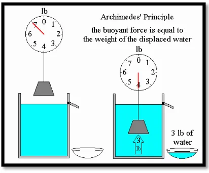
According to Yunus A.Cengel and John Cimbala (2006), they defined a fluids exerted an upward force on a body immersed in it is a buoyant force. The buoyant force is caused by the increase of pressure with depth in a fluid. To build an ROV, this factor must be considered. The buoyant force acting on a body of uniform density immersed in a fluid is equal to the weight of the float displaced by the body, and its acts upward through the centroid of the displaced volume. Thus, �= � �. Where ′�′ is density of force and „g‟ is gravity also volume. The buoyant force (FB) is equal to the displaced water. This fact is proven by Archimedes‟s on his principle in Figure 2.6.
8
Figure 2.6: Archimedes‟s principle
Figure 2.7: Solid body condition when drop into the water.
9
In the buoyancy concept, the stability also is important application to floating bodies with external attachments. This concept usually used in ships and submarine construction. Stability is tending of an object to return itself in equilibrium position when there is a small displacement.
The stability also has three conditions which is stable, unstable and neutrally stable. Stable is movement of an object and its will return back to the initial position. Its centre of gravity must below the centre of buoyancy. The movement of an object to new location when there is any small displacement is neutrally stable. Centre gravity is coincident with centre of buoyancy. As example, ball on the field kicked by someone. The ball will stop in new position. It has no tendency to move back to its original location, nor does it continue to move away. Unstable condition is object maybe at rest or never at rest when there is disturbance. Its centre gravity is above the centre of buoyancy. Figure 2.9 shows about stability and centre of gravity.
10
Figure 2.10: Stability concept used for the ship.
Figure 2.10 shows a floating body is stable if the body is (a) bottom bottom-heavy and thus the centre of gravity G is below the centroid B of the body, or (b) if the metacenter M is above point G. However, the body is (c) unstable if point M is below point G. While, Figure 2.10 is clarifies of submarine concepts, where (a) stable position is used.