UNIVERSITI TEKNIKAL MALAYSIA MELAKA (UTeM)
Engine RPM Based Sensing Techniques
Thesis submitted in accordance with the partial requirements of the
Universiti Teknikal Malaysia Melaka for the
Bachelor of Manufacturing Engineering (Hons)(Robotics and Automation)
By
Hairol Farisah Jaafar
Faculty of Manufacturing Engineering
ENGINE RPM BASED
SENSING TECHNIQUES
HAIROL FARISAH B. JAAFAR
UTeM Library (Pind.1/2007)
SESI PENGAJIAN : _______________________
Saya _____________________________________________________________________
mengaku membenarkan t esis (PSM/ Sarj ana/ Dokt or Falsaf ah) ini disimpan di Perpust akaan Universit i Teknikal Malaysia Melaka (UTeM) dengan syarat -syarat kegunaan sepert i berikut :
1. Tesis adalah hak milik Universit i Teknikal Malaysia Melaka .
2. Perpust akaan Universit i Teknikal Malaysia Melaka dibenarkan membuat salinan unt uk t uj uan pengaj ian sahaj a.
3. Perpust akaan dibenarkan membuat salinan t esis ini sebagai bahan pert ukaran ant ara inst it usi pengaj ian t inggi.
(Mengandungi maklumat yang berdarj ah keselamat an at au kepent ingan Malaysia yang t ermakt ub di dalam AKTA RAHSIA RASMI 1972)
(Mengandungi maklumat TERHAD yang t elah dit ent ukan oleh organisasi/ badan di mana penyelidikan dij alankan)
(TANDATANGAN PENULIS)
* Tesis dimaksudkan sebagai t esis bagi Ij azah Dokt or Falsaf ah dan Sarj ana secara penyel idikan, at au disert asi bagi pengaj ian secara kerj a kursus dan penyel idikan, at au Laporan Proj ek Sarj ana Muda (PSM). ** Jika t esis ini SULIT at au TERHAD, sil a l ampirkan surat daripada pihak berkuasa/ organisasi berkenaan
Engine RPM Based Sensing Technique
DECLARATION
I hereby, declared this project entitled “Engine RPM Based Sensing Technique” is the results of my own research except as cited in references.
Signature : ………. Author’s Name : ……… Date : ………
APPROVAL
This report submitted to the Senate of UTeM and has been accepted as partial fulfillment of the requirements for the degree of Bachelor of Manufacturing Engineering
(Robotics and Automation). The member of the supervisory committee is as follow:
………. Project Supervisor
ABSTRACT
ABSTRAK
DEDICATION
ACKNOWLEDGEMENTS
TABLE OF CONTENTS
List Of Abbreviations, Symbols, Specialized Nomenclature ……….. xi
6. SUMMARY AND CONCLUSIONS ……….. 51
6.1 Introduction ………... 51
6.2 Summary of Project ……….. 52
6.3 Conclusion ……… 53
REFERENCES ……….. 54
APPENDICES ……… 55
A
Complete System Assembly
B
Hall-Effect Sensor
C
Motor Driving the Rotating Body
D
The Processing System
E
The Output System
F
PCB Drawing For the Processor System
LIST OF FIGURES
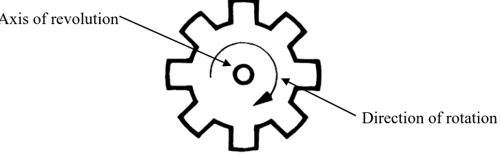
1.1 Gear, example of a rotating body
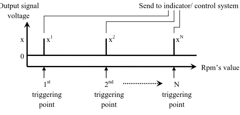
1.2 Expected linear correlation between engine rpm’s value and sensor’s output 1.3 Triggering points along the rpm range and the output signal
2.1 Tooth Ferromagnetic Wheel with known teeth, N 2.2 Sensor orientation
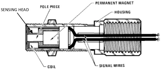
2.3 Variable Resistance pick-up sensor
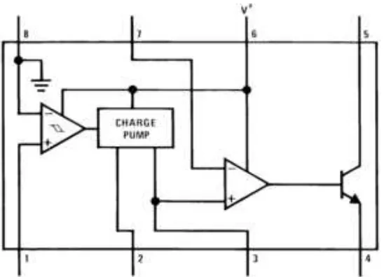
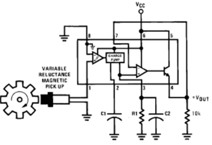
2.4 LM2907 building block and pin numbering 2.5 LM2907 connection
2.6 Transistor system as used for switch 2.7 The sensing apparatus
2.8 Idealized plot for an engine rpm curve vs. the sensor output signal curve and depicting the time relationship between two curves.
2.9 Flowchart for software algorithm used to determine engine position
3.1 Sample of a crankshaft
3.2 Hall-effect sensor sample image 3.3 Pin-outs of the LM2917
3.4 Sample of L.E.D. driven by LM3914 3.5 Full system diagram
3.6 8 volt regulated power supply circuit 3.7 5 volt regulated power supply circuit 3.8 Sensory component
3.9 The tachometer circuit 3.10 L.E.D. driver circuit 3.11 Stepper motor circuit
4.4 Oscilloscope output
4.5 Testing the tachometer circuit 4.6 Testing the L.E.D. driver circuit 4.7 Testing the stepper motor circuit 4.8 Complete system connected
5.1 Output of the hall-effect sensor sensing continuous rotation of the metal gear
5.2 LM2917 pin outs
5.3 Location of R1,C1 and C2 5.4 LM3914 pin outs
LIST OF TABLES
3.1 Resistance value within a pair of wire 3.2 Output of stepper motor
3.3 Stepper motor wire sequence
4.1 8 volt regulator output with varying input voltage 4.2 5 volt regulator output with varying input voltage 4.3 Sensory circuit output
4.4 Result of tachometer circuit testing 4.5 L.E.D. output
4.6 Output of stepper motor 4.7 Output of the system
LIST OF ABBREVIATIONS, SYMBOLS, SPECIALIZED
NOMENCLATURE
AC - Alternate Current
DC - Direct CurrentAnalysis of Variance EEM - Electronic Engine Management I.C. - Integrated Circuit
L.E.D. - Light Emitting Diode LCD - Liquid Crystal Display PC - Personal Computer
PIC - Programmable Input Controller PID - Proportional–Integral–Derivative PLC - Programmable Logic Controller PSM - Projek Sarjana Muda
RPM - Revolution per minute TDC - Top Dead Centre
CHAPTER 1
INTRODUCTION
1.1 Introduction
Speed sensing has grown along with the automation industry since the 1970’s. Today there are many type of speed sensing available whether it is a linear or angular motion speed sensing. The sensors vary from contact mechanical type sensor using linkage and gears, non-contact digital type sensors using magnetic system to optical sensor. This broad selection provides solution to particular speed sensing problem but not universally. For every moving or rotating body system, a unique system has to be developed to monitor the speed. Some other system can be adapted to the system while other cannot and new system has to be developed for them. For such reason this study is conducted in hope that a more universal system can be design and applicable to not only to sense engine rpm but other moving or rotating body as well.
1.2 Problem Statements
1.3 Objective of the Research
In this study, the main objective is:
(a) To detect angular speed of a rotating body (engine crank).
Figure 1.1. Gear, example of a rotating body.
(b) To produce a readable output corresponding to the engine’s rpm. - In the form of voltage or current reading
Figure 1.2. Expected linear correlation between engine rpm’s value and sensor’s output
(c) To produce an output signal when the rpm value equals to the defined triggering rpm point.
(d) To use the output as an input for indicator/ another control system. Axis of revolution
Direction of rotation
Voltage produced, V
Figure 1.3. Triggering points along the rpm range and the output signal
There are three basic needs that need to be fulfilled in achieving the above objectives. The first thing is to determine a suitable existing output from the engine to be the input to the system. The second thing is to select from the wide selection of sensors available which type of sensing that will most suited the study. The third thing is to determine what kind of system that will convert signal sense by the sensor into a form of rpm value.
1.4 Scope
There are certain limitations and borders set to help in focusing in what is important and needed in this project. The scope is set by considering the relevancy of the components to this course and project.
The scope in this study will cover: (a) Design of sensing system.
(b) Design of signal processing and output system from the sensor. (c) Design of a prototype of the complete system.
(d) Fabricating and development of the system into working prototype.
x1 x2 xN
This study will not cover:
(a) Detail designing of the electronic system.
(b) Building circuit from scratch. Standard parts such as integrated circuit will be used whereas possible as this is not an electronic project.
1.5 Significant of Study
Although a lot of manufacturer have already produced many type of rpm sensor (tachometer), a universal type of rpm sensing system is still hard to find. There is still less type of sensor that can be simply mounted on a rotating body and get the reading instantly without much hassle. This system also can give many benefits to the automation sector as there is a lot of area where speed control is needed and crucial. The realization of this project can provide more opportunities in improving the automation industries.
1.6 Conclusion
CHAPTER 2
LITERATURE REVIEW
2.1 Introduction
Researches throughout the globe regarding this topic are not very easy to find. However by searching through the sub component of the project it can be found. This review gives a brief description about the level of development of sensing system and signal processing nowadays. From the information based on the literature reviewed, the tooth-wheeled variable reluctance sensing system is used as it suits this project the most. The three basic parts which are the sensor, processing part and the output part selected are explained below.
2.2 The System
The system is built based on a crankshaft position sensor system. The only requirement needed for a system to be mounted with such system is that the rotating body to be measured must have toothed ferromagnetic wheel as in figure below:
The sensor will be mounted in front of the rotating tooth as follows:
Figure 2.2. Sensor orientation
Ferromagnetic materials are material that is ferrous based (steel) and react to magnet. The example is such as mild steel and stainless steel which is really easy to find especially on a rotating shaft. The example of tooth ferromagnetic wheels can be found on engine’s flywheel, gears and transmission and bike’s sprocket.
2.2.1 The Sensor
The selected sensor comes from non-contact sensor family called variable reluctance sensor. The sensing architecture consists of a permanent magnet and two pick-up coil as shown below.
Figure 2.3. Variable Resistance pick-up sensor
SENSING HEAD
The reason behind this selection from all other sensor in the market is the simple and robust design. There are only two working components and there is no contact part. The sensor is fully encapsulated inside housing that covers all the part to protect it from the environment. This means it is rigid, reliable and has a relatively long lifespan. It has been used in automotive industry for crankshaft positioning sensor and proven its average lifespan is longer than the vehicle itself. It is made from common material thus the cost is low.
However, there is some problem faced when using this sensor. This sensor operates based on Faraday’s Law where the output voltage changes linearly with the magnetic flux variation (produced when toothed steel wheel cut through the flux). From this law, the output voltage does not increase linearly but produces a continuous sinusoidal voltage wave form where the frequency varies linearly to the toothed steel wheel speed. Therefore, a circuitry system needs to be design to process and convert the frequency input into voltage so it can be displayed on a voltmeter as the rpm display system.
2.2.2 The Processing System (LM2907)
For the signal processing part, a standard part LM2907 is used. It is a frequency to voltage converter chip with built-in input hysteresis amplifier, charge pump and op amp/ comparator. The building block for the chip when connected to the sensor will be as follows:
Figure 2.5. LM2907 connection
The operating concept of the circuit will not be explain in detail because it is more on electronics which is outside the scope of this study. The basic operation of the system consists of three main components as follows;
(a) Input hysteresis amplifier (signal conditioner)
- amplify the signal, filter the noise, produce binary signal (on-off) from the sinusoidal wave form.
(b) Charge Pump
- act as a capacitor, collect the voltage signal and discharge it at a constant rate.