OPTIMIZATION OF MECHANICAL COUPLING IN ELECTRIC VEHICLE (ev)
KAMARULHELMY BIN TALIB
OPTIMIZATION OF MECHANICAL COUPLING IN ELECTRIC VEHICLE (ev)
KAMARULHELMY BIN TALIB
This report is submitted in accordance with requirement for the Bachelor of Mechanical Engineering (Automotive)
Faculty of Mechanical Engineering Universiti Teknikal Malaysia Melaka
i
SUPERVISOR DECLARATION
“I hereby declare that I have read this thesis and in my opinion this report is sufficient in terms of scope and quality for the award of the degree of
Bachelor of Mechanical Engineering (Automotive)”
Signature : ………..
Supervisor : Dr Noreffendy Bin Tamaldin
DECLARATION
“I hereby declare that the work in this report is my own except for citation and quotation that the sources has been clarified for each one of them”
Signature : ………..
Author : Kamarulhelmy Bin Talib
iii
DEDICATION
I dedicated this report to my beloved mother, Kemariah Binti Dagang,
ACKNOWLEDGEMENT
All praises and thanks be to Allah S.W.T. who has guided us to this, never could we have found guidance, were it not that Allah had guided us! (Quran 7:43)
Greatest gratitude to my supervisor, Dr Noreffendy Tamaldin for his supervision, advice, guidance and his time spent for me throughout my final year project. He always gives me moral support and motivation whenever I have problems in completing my project. Without him, I would never able to finish this project. His constant encouragement and guidance have brought me to the final stage of my project.
I also like to whole-heartedly thanks to my friends, especially Muhammad Zikrillah and Bong Soon Siong for their help and idea in helping me to complete my final year project.
Special thanks to my mother, Kemariah Binti Dagang because give me all her support, motivation and care in the time I sick and well. Thanks also to my family especially my sister, Noorhafizah Binti Talib in helping me done my final year project.
v
ABSTRACT
ABSTRAK
vii
TABLE OF CONTENTS
CHAPTER TITLE PAGE
SUPERVISOR DECLARATION i
DECLARATION ii
DEDICATION iii
ACKNOWLEDGEMENT iv
ABSTRACT v
ABSTRAK vi
TABLE OF CONTENTS vii
LIST OF TABLES ix
LIST OF FIGURES x
LIST OF SYMBOLS xiii
LIST OF APPENDICES xiv
1 INTRODUCTION
1.1 Project Background 1
1.2 Problem Statement 1 - 2
1.3 Objectives 2
1.4 Scopes 2
2 LITERATURE REVIEW
2.1 Evergreen’s Mechanical Coupling System 3
2.2 DC Electric Motor 4
2.3 5-Speeds Manual Transmissions 4 – 5
2.4 Adapter Plate 5 – 6
CHAPTER TITLE PAGE
2.6 Design for Manufacturing (DFM) 7 – 8
2.7 SolidWorks Software 8 – 9
2.8 Finite Element Analysis (FEA) 9 – 10
2.9 Mechanical Coupling Analysis 10
2.9.1 Static Analysis 11 – 12
2.9.2 Buckling Analysis 13 – 14
3 METHODOLOGY
3.1 Introduction 15
3.2 Mechanical Coupling System 15 – 17
3.3 Boundary Conditions of Mechanical Coupling 17 – 18 Fixtures Apply to Mechanical Coupling 18 – 19 Loads Acting on the Mechanical Coupling 20 – 21
3.4 Meshing 22 – 23
4 RESULT AND DISCUSSION
4.1 Introduction 24
4.2 Result of Static Analysis at Torque = 130 Nm 25 – 28 4.3 Result of Static Analysis at Torque = 60 Nm 29 – 32 4.4 Result of Buckling Analysis at Torque = 130 nm 33 – 34 4.5 Result of Buckling Analysis at Torque = 60 nm 35 – 36 4.6 Discussion for Static Analysis 37 – 38 4.7 Discussion for Buckling Analysis 38 – 40 4.8 Design for Manufacturing (DFM) Analysis 40 – 42
5 CONCLUSION AND RECOMMENDATION
5.1 Conclusion 43
5.2 Recommendation 44
References 45 – 47
ix
LIST OF TABLES
NO TABLE PAGE
2.3.1 The gear ratio of the 5-speed manual transmission (Source: UTeM’s PGMC Presentation, 2012)
5
2.6.1 The consideration taken in DFM 7 2.9.1 The interpretation of the buckling load factor (BLF)
(Source: Akin J.E., 2010)
14
3.3.1 Volumetric Properties and Material Properties of Mechanical Coupling
18
4.6.1 The results of Static Analysis at Torque 130 Nm and 60 Nm
37
4.7.1 The results of Buckling Analysis at Torque 130 Nm and 60 Nm
38
4.7.1 Design for Manufacturing (DFM) Analysis of Mechanical Coupling
LIST OF FIGURES
NO FIGURES PAGE
2.1.1 The arrangement of Evergreen’s Mechanical Coupling System (Source: UTeM’s PGMS Presentation, 2012)
3
2.4.1 The design of the adapter plate by using Catia 6
2.5.1 The side view of the Shaft Coupler 7
2.5.2 The lower side of the Shaft Coupler 7
2.8.1 Example of mesh application on a part. (Source: www.tms.org, (14th April 2013))
10
3.2.1 Exploded Drawing of Mechanical Coupling System 16
3.2.2 The position of Mechanical Coupling 16
3.3.1 The dimensions of Mechanical Coupler 17
3.3.2 The blue region shows the surface that undergoes roller/slider fixtures
18
3.3.3 Fixtures at bolts that connect Mechanical Coupling and DC Electric Motor
19
3.3.4 Fixtures at key slot 19
3.3.5 Fixtures at bolts that connect Mechanical Coupling and Flywheel
19
3.3.6 Forces acting on Mechanical Coupling 20
3.3.7 Torque applied to the Mechanical Coupling 21 3.3.8 The forces exerted to Mechanical Coupling by bolts
that connect it with Flywheel
21
3.4.1 The mesh model of Mechanical Coupling 22
xi
4.2.2 Position of Minimum von Mises Stress occur at Torque 130 Nm
26
4.2.3 Position of Maximum von Mises Stress occur at Torque = 130 Nm
26
4.2.4 Resultant Displacement that occur at Torque = 130 Nm
27
4.2.5 Equivalent Strain at Torque = 130 Nm 28 4.3.1 von Mises Stress result at Torque = 60 Nm 29 4.3.2 Position of Minimum von Mises Stress occur at
Torque = 60 Nm
30
4.3.3 Position of Maximum von Mises Stress occur at Torque = 60 Nm
30
4.3.4 Resultant Displacement that occur at Torque = 60 Nm
31
4.3.5 Equivalent Strain at Torque = 60Nm 32
4.4.1 The result of Buckling Analysis at Torque = 130 Nm
33
4.4.2 Position of Maximum Buckling Displacement occur at Torque = 130 Nm
34
4.4.3 Position of Minimum Buckling Displacement occur at Torque = 130 Nm
34
4.5.1 The result of Buckling Analysis at Torque = 60 Nm 35 4.5.2 Position of Maximum Buckling Displacement occur
at Torque = 60 Nm
36
4.5.3 Position of Minimum Buckling Displacement occur at Torque = 60 Nm
36
4.7.1 Position of Resultant Buckling Effect at Torque = 60 Nm
39
4.7.2 Position of Resultant Buckling Effect at Torque = 130 Nm
39
4.8.1 The blue region is the part where milling process have problem to produce
41
xiii
LIST OF SYMBOLS
= Maximum von Mises Stress = Yield Strength
= Stress = Strain
= Magnitude of Deformation (or Displacement) L = Length of the part
= The additional “geometric stiffness” due to the stresses caused by the loading
LIST OF APPENDICES
APPENDIX A PSM Gantt Chart APPENDIX B Flywheel Dimensions APPENDIX C Cover Plate Dimensions APPENDIX D Key Slot Dimensions APPENDIX E Calculation of bolts
1
CHAPTER 1
INTRODUCTION
1.1 Project Background
In year 2012, PROTON Holdings Berhad (PROTON), a Malaysian automotive company, and Agensi Inovasi Malaysia (AIM) have organized Proton Green Mobility Challenge (PGMC). This competition is held as path of collaboration between universities and industry in order to develop an electric vehicle based on the conventional Proton Saga specification and features. Ten universities is chosen to enter the competition and UTeM is one of it. Every team is given about 10 months to complete their electric vehicle from January 2012 until the day of competition that is 5-7th October 2012. In 10 months, every team need to transform a conventional Proton Saga BLM into an Electric Vehicle. This transformation including the removing of ICE engine, the installation of electric motor, implementing new mechanical coupling system, the changes to the cooling system, the installation of battery and many more.
1.2 Problem Statement
system is unknown. Study on the mechanical coupling system is required to analyze problems that may occur to the mechanical coupling system and data obtain from the analysis can be used to optimize the performance of the system.
1.3 Objectives
The main purpose of this study is to study the mechanical coupling that have been implemented in UTeM’s electric vehicle, Evergreen. Analysis is done to identify any weakness and failure that may occur in the mechanical coupling system since the system does not going through any proper analysis before the system is set up in Evergreen.
1.4 Scopes
3
CHAPTER 2
LITERATURE REVIEW
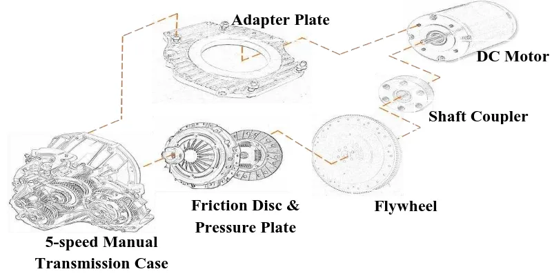
2.1 Evergreen’s Mechanical Coupling System
Mechanical coupling in Evergreen is a set of components that combined power source (in this case DC Motor) and transmission (5-speed transmission system). Mechanical coupling system is placed between DC Motor and transmission. The components are Adapter Plate, Friction Disc, Pressure Plate, Flywheel and Shaft Coupler. The arrangement of the Mechanical coupling component is as shown in Figure 2.1.1 below.
Figure 2.1.1: The arrangement of Evergreen’s Mechanical Coupling System (Source: UTeM’s PGMS Presentation, 2012)
5-speed Manual Transmission Case
Adapter Plate
DC Motor
Flywheel Friction Disc &
Pressure Plate
2.2 DC Electric Motor
There are many types of electric motor. It comes in various shape, weight and size depend on its functions. Electric motor is used in almost everything like toys, robot, CD players, watches, subway trains and many more. The main function of electric motor is similar for every type, which is to convert electrical energy into mechanical energy. Basically, there are two types of electrical motor that is Direct Current (DC) electric motor and Alternating Current (AC) electric motor. DC electric motor is motor that runs on direct current, which the current flow in the circuit is in one direction only. AC electric motor is a motor that runs on alternating current, which the direction of current flowing in a circuit is constantly being reversed back and forth.
The specification of DC motor used in Evergreen is a DC motor with power of 25kW and powered with up to 144V battery. The power of the DC motor can achieved 60kW at peak power supply. The DC motor can achieved speed up to 4000rpm. The average torque produce is 60Nm and can achieved up to 130Nm. Average current flow in the motor is 191.4A and can achieved until 380A. The weight of the DC motor is 58kg and has efficiency of 94.8%. (Source: UTeM’s PGMC Presentation, 2012)
2.3 5-Speeds Manual Transmission
5
energy at lower at lower drive wheel speed by spinning more slowly than crankshaft while the smaller gear (high gear) convert lower engine rpm into higher speed and efficiently by spinning faster than crankcase
Basically, there are two types of automobile transmission system, which is manual and automatic. A manual transmission system is an assembly of shafts, gears, and related parts contained in a metal case or gearbox partially filled with lubricant. In manual transmission system, gears are selected manually by the driver. The driver will decide whether he want to set low gear or high gear, to reverse or to move forward. An automatic transmission system is a transmission that can change gear ratios automatically as the vehicle moves. In automatic transmission, the driver only needs to operate a gear-shift once (forward or reverse) and do not need to control a clutch. The transmission system will decide when to change the gear ratios by referring to the rpm of the engine.
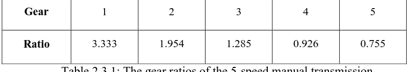
The transmission system that used in Evergreen is a manual 5-speed transmission system. This transmission is the actual transmission been used in Proton Saga BLM. The condition of PGMC (Proton Green Mobility Challenge) competition stated that every participants need to change the ICE engine of the Proton Saga BLM with a DC electric motor, but they need to used the 5-speed manual transmission that already in the vehicle. The 5-speed transmission system in Evergreen is a transmission that contains 5 choices of gears (gear 1 until gear 5) with additional reverse gear. The gear ratio for every gear in this transmission system is as stated in Table 2.3.1 below:
Gear 1 2 3 4 5
Ratio 3.333 1.954 1.285 0.926 0.755
Table 2.3.1: The gear ratios of the 5-speed manual transmission (Source: UTeM’s PGMC Presentation, 2012)
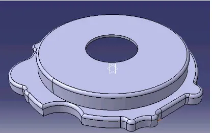
2.4 Adapter plate
with the profile of the plate follow the profile of the transmission bell housing. This plate is made from aluminium with thickness 5mm. The adapter plate is bolted to DC motor register at one side and transmission bell housing at another side. Another function of this plate is to ensure the clutch fluid that will be inserted in the mechanical coupling does not flow out from the mechanical coupling system. Figure 2.4.1 below shows the design of the adapter plate by using Catia. The dimensions of adapter plate can refer to Appendix C
Figure 2.4.1: The design of the adapter plate by using Catia.
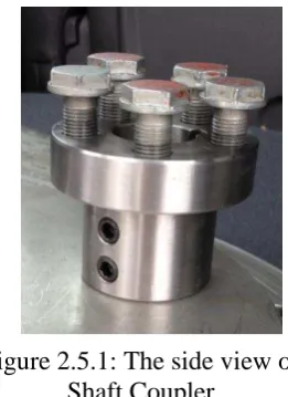
2.5 Shaft Coupler
7
2.6 Designs for Manufacturing (DFM)
DFM is the method used when designs a product with aiming for manufacturing of the products. DFM is the first step for anyone that want to develop the product so that it capable to be done in massive manufacturing and sell to public. DFM is like an umbrella that covers variety of tools and techniques to accomplish a manufacturable product. The application of DFM can help the industry in lowering their development cost, shorting their development time; enhance faster manufacturing start of build, lowering assembly and test costs without effect the quality of the product developed.
The objectives of DFM method is to identify product concepts that are easy to manufacture and can sell to public with low cost. DFM is focus on component design for the ease of manufacturing and assembly. It’s focused to design a product that easy to manufacture and assembly. There are several factors been considered in DFM that is environmental, customer, supplier, and process and tooling. Table 2.6.1 below shows the consideration of DFM by respect to its factors:
Table 2.6.1: The consideration taken in DFM
FACTORS EXAMPLES
Environmental
Ergonomics Safety Pollution Recycling Shock/vibration Temperature Figure 2.5.1: The side view of
Shaft Coupler
Customer
Depth of product line Customization Test requirements
Suppliers
Cycle time Quality
Ease of Assembly Ease of Testing Rework
Shipping and Handling Tooling Costs
Process and Tooling
Partnerships
Supplier tolerance capability Merging mechanical
sub-assemblies Costs
2.7 SolidWorks Software
SolidWorks is a 3D mechanical CAD (Computer Aided Drawing) software that developed by Dassault Systemes SolidWorks Corporation. SolidWorks is software that can help its users to enhance their imagination into reality. SolidWorks can help in drawing and developed 3D designs in easy ways, without needed to use traditional method (by using hand and Engineering drawing tools). This easy-to-learn software help mechanical designer to quickly sketch ideas, experiment with features and dimensions, and produce models and detailed drawings.
This software also comes with the features to do analysis to the product design in its. By using the principle of Finite Element Analysis (FEA), this program capable of doing static analysis, dynamic analysis thermal analysis, drop test analysis, fatigue analysis and many more. These features can be used to help in doing analysis of the Evergreen’s mechanical coupling system. The analysis of the mechanical coupling can only be done virtually since the coupling system that already implement in Evergreen cannot disassembled anymore.