ISSN: 1693-6930
accredited by DGHE(DIKTI), Decree No: 51/Dikti/Kep/2010 337
UHF RFID Tag Antenna for Vehicle License Plate
Number (e-Plate)
Evizal1, Tharek Abdul Rahman2, Sharul Kamal Abdul Rahim3 Wireless Communication Centre, Faculty of Electrical Engineering
Universiti Teknologi Malaysia, 81310, Johor, Malaysia Ph.: +607 553 5305, Fax: +607 553 5252
e-mail: [email protected], [email protected], [email protected]
Abstrak
Penelitian ini menampilkan desain baru antena RFID UHF untuk plat nomor kendaraan (e-plate). Plat nomor yang diusulkan tidak memerlukan perangkat lain karena setiap kendaraan telah dilengkapi plat nomor sebagai identitas kendaraan dan e-plate ini telah tertanam didalamnya. Bahan digunakan pada pembuatannya adalah FR4 yang cukup murah dengan hasil telah terjadi peningkatan kinerja dibandingkan antena yang ada saat ini. Desain antena yang diusulkan bekerja pada rentang frekuensi 902-928 MHz untuk aplikasi RFID UHF dengan gain antena sebesar 3.8 dBi. Antena ini berbentuk kotak dan meiliki dimensi sebesar 300 mm x 100 mm, yang umumnya juga merupakan ukuran plat nomor konvesional. Respon yang cukup baik diperoleh melalui simulasi pada frekuensi pusat 915 MHz dengan koefisien refleksi sebesar -57.7 dB. Kinerja antena e-plate diuji lebih lanjut dengan memasangkan RFID tag chip dan menanamkannya pada plat nomor kendaraan yang sesungguhnya. Pengujian awal di lapangan menunjukkan bahwa jarak pembacaan maksimum mampu mencapai 12 meter.
Kata kunci: RFID, antena, e-plate
Abstract
In this research presents a new design of UHF RFID tag antenna for vehicle license plate number (e-plate). The proposed e-plate does not require another gadget or equipment since every vehicle is attached with a vehicle registration plate number and this e-plate embedded together. A low cost FR4 material has been used for its fabrication and there is performance improvement compared to the current tag antenna. The proposed antenna design works at 902-928 MHz frequency band for UHF RFID application with 3.8 dBi antenna gain. The antenna is rectangular in shape and has a dimension of 300 mm x 100 mm, which is usually the typical size of the conventional vehicle registration plate number. Acceptable responses were obtained in simulation at centre frequency of 915 MHz with reflection coefficient of -57.7 dB. The performance of proposed e-plate antenna was further tested by attaching a RFID tag chip and embedded it to the actual vehicle plate number. Initial testing on the field by attached e-plate on vehicle was achieved maximum reading range of up to 12 meters.
Keywords: RFID, antenna, e-plate
1. Introduction
Radio Frequency Identification (RFID) is a technology that used radio frequency waves and incorporates of electromagnetic or electrostatic coupling in portion of the electromagnetic spectrum to uniquely identify an object, animal, or person [1]. RFID is one of the promising technologies employed as an alternative for overcoming some issues associated with current technology used for identifications, such as bar code and optical systems.
Many research have done in the RFID fields are discussed about object tagging and identification, as reported in [2]-[6] new design of tag antenna, tagging method, used different material and so on. Some others research discussed in object tagging for the metallic object and metallic environment as in [7]-[11] proposed for different kind of metallic object, size and technique.
which is attached to vehicle therefore these properties of vehicle become one of tracking and identification system. In order to improve the performance, RFID technologies can be used as a transponder for vehicle registration plate number, whereby the proposed antenna with RFID chip serves as the electronic plate (e-plate) instead of using the conventional tag antenna currently available in the market, beside that with this tag antenna may improve the reading range.
Several methods and techniques for e-plate antenna and tag design have been reported. E-plate antenna design using slots to serve as RFID tag was reported in [12] but this method used 2.45 GHz band which is active RFID system where the constraint is cost of tag. In [13], the proposed e-plate antenna uses velocity technique, where the minimum time for one single tag to be effectively read but also used active tag. Some others research findings were reported in [14]-[16], the proposed tag antenna is installed as a tag inside a car’s side-view mirror for optimum reading. All the proposed used compact antenna where low in gain, which is similar to the current antenna in the market.
In this research, the proposed of e-plate antenna uses a passive RFID type, which is much cheaper and requires no battery, compared to active RFID type. In addition, the proposed antenna designed embedded to the tag with dual side beam and utilize as much the size of standard vehicle plate number for better antenna design and performance, optimum reading of RFID e-plate much higher compare to current compact antenna.
2. Tag Antenna Design
The proposed antenna is designed to radiate in a bi-directional beam pattern, where multi beam for tag reading can be more conveniently achieved. On a typical road, RFID readers are normally installed at the road side, so that the tags are read at either the left side or right side of the beam. The antenna is fabricated using a readily available and inexpensive FR4 material, with the following specifications: relative permittivity of = 4.7, height h = 1.6 mm and tan δ = 0.019. Common vehicle licence plate number has a rectangular shape with average length and width of 100 mm and 300 mm, respectively. The proposed antenna also has a rectangular pattern similar dimension as the vehicle licence plate number.
2.1. Antenna Design and Optimization
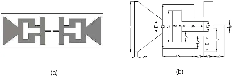
Figure 1 shows the proposed antenna design and its dimensions in rectangular shape. This folded antenna consists of two mirror radiating elements (left and right sides) separated with 5mm for RFID tag chip, a proposed scheme for achieving multi beam radiation pattern [17]. The antenna is designed in a single layer while the radiating elements, copper material of 0.035 mm thickness, are placed on top of substrate. Dimensions of the proposed antenna are summarized in Table 1. Unlike directional patch antennas which normally have single radiation pattern, the proposed antenna has dual radiating elements for generating multi beam radiation pattern. The two ends of radiating elements are designed as V-shape structure [18] with width and length of 45 mm and 80 mm, respectively, in order to achieve diagonal radiation pattern.
(a) (b)
Proposed antenna was simulated using 3D CST simulation software here a discrete port has been used to represent RFID tag terminal. There is a gap of 5 mm between the two edges of discrete port, which is the normal size of UHD RFID tag chip. The simulated results of proposed antenna are expected to give acceptable performances at a centre frequency of 915 MHz band for UHF RFID application. This is in accordance with the FCC standardization, which recommends a frequency band of 902-928 MHz for UHF RFID. This implies that the antenna minimum bandwidth would be 26 MHz in order to comply with the standardization. The gain of proposed antenna is 3.8 dBi, which is much higher compared to the current inlay tag antenna.
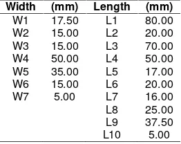
Table 1. Optimum parameter value of the proposed antenna.
Width (mm) Length (mm) W1 17.50 L1 80.00 W2 15.00 L2 20.00 W3 15.00 L3 70.00 W4 50.00 L4 50.00 W5 35.00 L5 17.00 W6 15.00 L6 20.00 W7 5.00 L7 16.00 L8 25.00 L9 37.50 L10 5.00
Proposed antenna structure consists of several in width and length of elements. One of the most dominant changes observed in simulation results is the width of W7. The parametric studies have been conducted in order to achieve optimum width during simulation stage of proposed antenna. Figure 2 shows simulation result of the parametric studies for the width of W7=0, and the response of reflection coefficient upper at the centre frequency is 915 MHz. Increasing the width to W7=10 mm gives a lower response than center frequency. Our studies have shown that the optimum width of W7=5 mm is required to achieve good response at the center frequency, 915 MHz. At operating frequency of 915 MHz, the simulated value of reflection coefficient is -57.7 dB. The corresponding value of simulated bandwidth is 30 MHz. It should be noted that the proposed antenna is also suitable for UHF RFID applications in the operating frequency band of 902-928 MHz, as originally proposed for the e-plate.
Figure 2. Parametric study results of antenna.
Figure 3. Fabrication of the proposed UHF RFID tag antenna for e-plate application.
2.2. Tag Impedance
In the designing an antenna a few parameters of antenna properties need to take attention, one of the parameter is antenna input impedance. Normally impedance of the antenna is 50 ohm and feed by coaxial cable or feeder with same impedance, some equipments or devices has impedance 75 ohm or 300 ohm for the transmitter and antenna. Mismatch impedance of antenna and transmitter will effect for high reflection coefficient and result low performance of the system.
In order to achieve optimum performance of the system, good matching input impedance of proposed antenna to tag chip is importance. In this research the design of antenna is not for transmitter but for RFID tag chip and become RFID tag. Equation (1) shows the reflection coefficient of RFID tag is|Γ|2tag [19-20], where Zc is impedance of RFID tag chip and Ra is impedance of RFID tag antenna. Normally for a passive RFID chip, the power reflection coefficient is always smaller than unity.
|Γ| = ( )
( ) (1)
where, 0 ≤|Γ|2tag≤ 1
Before designing the antenna, selection of RFID tag chip is needed because different manufacturer has different RFID chip impedance and effected to matching of RFID tag. The impedance of RFID tag chip is commonly low in resistance and high in reactance, which is different to normal antenna. Monza 3 RFID tag chip from Impinj choose for this tag antenna design, with complex chip impedance is 32 + j216 ohm for the centre frequency at 915 MHz [21].
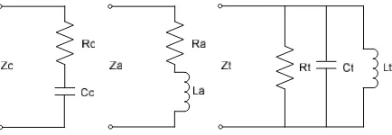
Figure 4. Equivalent circuit (a) tag antenna (b) tag chip and (c) RFID tag input impedance.
The configuration of proposed RFID tag antenna for e-plate as shown in Figure 1 consists of two symmetric rectangular radiating elements and no ground element. The two elements are electrically connected to the RFID chip via the gap of antenna at the centre of structure. Figure 4 shows the lumped simplified circuit equivalent of impedance tag antenna; tag chip and RFID tag [4, 22-23]. Detail of lump elements and impedance of RFID tag will not discuss in this research but equivalent of input impedance can be determined as equation (2).
Z = + C (2)
The resonance frequency of antenna fc determines by elements of capacitance and inductance which is Ct and Lt, in equation can be shows as 1/(2π√LtCt). In this proposed of antenna element of capacitance is properties of RFID chip and element of inductance part of
Right radiating Element Left radiating
antenna design, thus resonance frequency determine and can be controlled by length of antenna structure. During antenna design and optimization the main and major part effect to inductance of antenna is width of structure W7. To achieve resonance frequency at 915 MHz as proposed centre frequency for RFID tag, the width of element W7 optimize at 5mm.
3. Measurement and Testing Setup
The objective of this research is to increase the RFID tag reading range, due to the limited range of current tag antenna. This is achieved by ensuring that the antenna’s size is the similar as that of vehicle plate number. Moreover, the proposed antenna has higher gain and better radiation pattern. Figure 5 shows diagram of measurement setup proposed tag antenna to be test in anechoic chamber.
Figure 5. Measurements setup in anechoic chamber for RFID tag sensitivity.
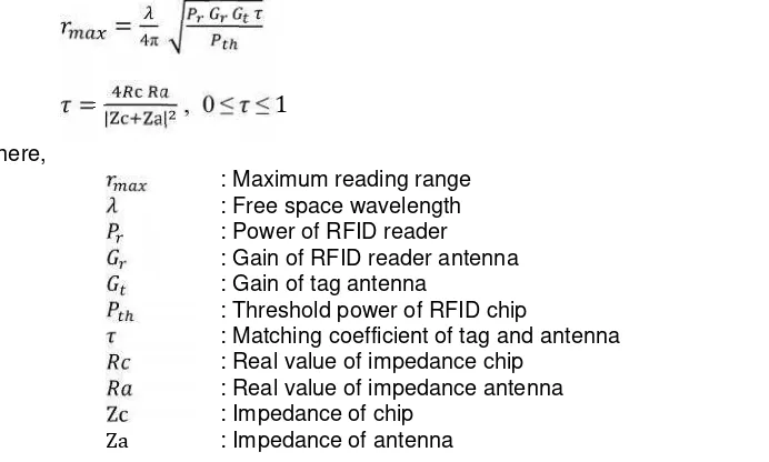
In passive UHF RFID system, one of the important parameter is reading range performance. Theoretically maximum reading range of passive tag can be calculate used Friis Transmission formula [19] as equation (3), one of parameter to define reading range of tag is coefficient between the tag chip and tag antenna as equation (4), when the impedance of the tag antenna and RFID chip are conjugate matching, the matching coefficient of will get the maximum value of 1 and fully energy will be received from tag antenna to the tag chip when RFID reader antenna is being enquired.
=
π (3)
=
| |
, 0
≤
≤
1
(4)where,
: Maximum reading range : Free space wavelength : Power of RFID reader : Gain of RFID reader antenna : Gain of tag antenna
: Threshold power of RFID chip
: Matching coefficient of tag and antenna : Real value of impedance chip
: Real value of impedance antenna
Zc : Impedance of chip
Za : Impedance of antenna
antenna used to transmit power and data to the proposed tag antenna, sensitivity of signal transmitted by the tag recorded by the computer. Its performances measured in terms of both vertical and horizontal radiation patterns are tested, where the holding gauge can be turn around 360 degrees.
(a) (b)
Figure 6. Measurements of RFID tag sensitivity Proposed e-plate antenna (b) Anechoic chamber room.
Measurement setup is aimed at testing the antenna radiation pattern in E-field and H-field; and a graph is then plotted to analyze the performances. A centre frequency of 915 MHz was used for testing the antenna, which complies with the UHF RFID standardization. The test results obtained from the measurements would be compared with the standard requirements to ascertain the acceptability of the proposed antenna.
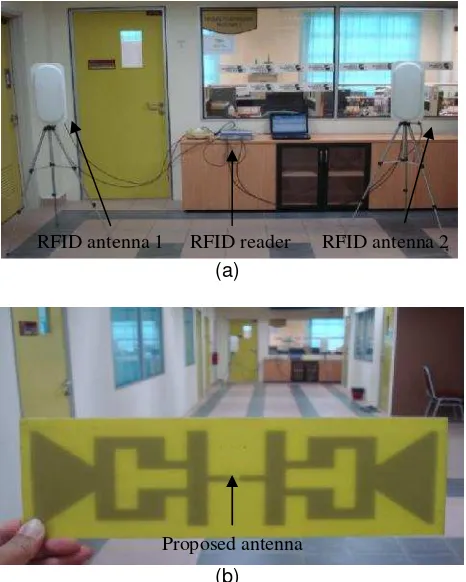
(a)
(b)
Figure 7. Measurement setup (a) UHF RFID reader with two units of antenna, (b) proposed antenna being test.
RFID antenna 1 RFID reader RFID antenna 2
An initial testing of proposed e-plate antenna was done in house (indoor environment) to see the performance and maximum reading range of antenna also compared to the performance of current tag antenna. The experimental setup for the testing is shown in figure 7. The two units of UHF RFID reader antennas used for this testing are shown in figure 7(a). Since proposed antenna has multi beams, where major beam is toward left hand side and right hand side, then it implies that dual RFID signal is received by the proposed e-plate antenna from left and right hand sides. A field UHF RFID reader, with four transmits and receives channels, is used in the testing. The power of reader is set to maximum is 32.5 dBm, as this is the global standard. Figure 7(b) shows the proposed antenna being moved from minimum to maximum reading range. The maximum reading range recorded between the reader antenna and the e-plate antenna is 12 m.
(a) (b)
Figure 8. Proposed e-plate antenna (a) common shape vehicle plate number (b) proposed e-plate attached.
Most of vehicle plate number shape in most of countries is in rectangular shape, this similar to the shape of proposed e-plate antenna, else the design of e-plate antenna maximize of normal plate number size. Figure 8(a) shows the most commonly used vehicle plate number with rectangular shape, while Figure 8(b) shows proposed antenna attached within a vehicle plate number (e-plate). The antenna attached inside of plate number frame, while the thickness of e-plate antenna is 1.6 mm. A vehicle normally has two plate numbers which is at the front and rear of vehicle, to ensure high performance in term of detection or tracking of RFID tag so in this proposed e-plate antenna also installed at both of front and rear of vehicle.
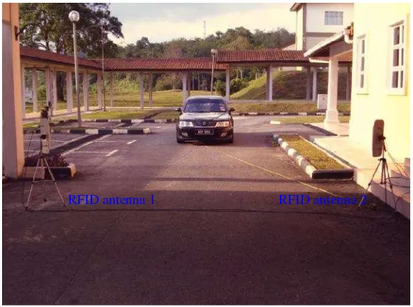
Figure 9. Field testing of proposed e-plate antenna installed on vehicle.
Another test have been conducted to the proposed e-plate antenna is field testing to the live vehicle, this to check maximum reading and performance of e-plate while installed on vehicle. Figure 9 shows field testing setup proposed e-plate antenna installed on vehicle and conduct testing of reading range and performance. In the field testing RFID reader with four channels (four transmitters and four receivers) is used same as in initial testing previously. Two units of bi-directional RFID antenna used for the testing with gain of each antenna is 7.9 dBi, while RFID reader model used is M5 series from ThingMagic and power of RFID reader set to the maximum which is 32.5 dbm. A pair of coaxial cable to feed RFID reader to antenna with length is 5 meter, low loss cable LMR-240 from Times Microwave and R-TNC RF connector. The test conducted start by move the vehicle away from the RFID antenna until no detection, than move the vehicle closer to the RFID antenna. First detection of e-plate tag data by reader is within distance of RFID antenna to vehicle is 12 meter. Test continues by move vehicle closer to RFID antenna until to the 0 meter, mean plate number same line as RFID antenna. RFID reader recorded within 10–11 meter distance between antennas to plate number, the reading of e-plate data is started better and closer to reader the sensitivity of received signal become higher. The aim of this field test is to check maximum reading range of proposed e-plate by installed to live vehicle and no speed been consider.
4. Results and Discussion
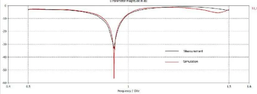
The simulated and measured values of reflection coefficient, at an operating frequency of 915 MHz, are -57.7 dB and -31.5 dB, respectively. The corresponding simulated and measured values of bandwidth are 100 MHz 110 MHz. The proposed antenna is also suitable for UHF RFID applications in the operating frequency band of 902 MHz to 928 MHz, as originally proposed for the electronic vehicle plate number application (e-Plate). Figure 10 shows both simulated and measured reflection coefficient graphs of the proposed antenna. It can be observed that both simulation and measurements results closely agree.
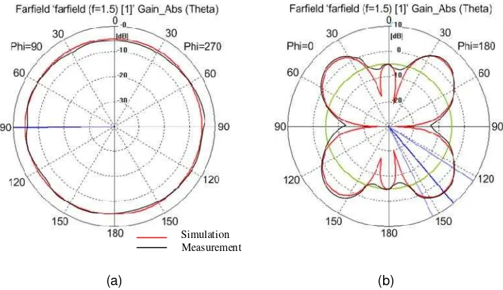
Figure 10. Polar radiation pattern of antenna at 915 MHz (a) H-Field (b) E-Field
(a) (b)
Figure 11. Polar radiation pattern of antenna at 915 MHz (a) H-Field (b) E-Field
5. Conclusion
A new design of UHF RFID tag antenna for vehicle plate number (e-plate) is proposed. The proposed antenna design has a rectangular shape with dimensions of 300 mm by 100 mm. The antenna operates at 902–928 MHz, according to standardization for UHF RFID applications. The antenna has been tested by being attached to an actual vehicle plate number with embedded UHF RFID chip. Acceptable responses were obtained for all the testing, simulations, and measurements carried out to evaluate its performance. The simulated bandwidth is 100 MHz at the centre frequency is 915 MHz.
A multi radiation pattern was achieved in the proposed design with no ground element, and the major radiations occur at both diagonal left and right hand sides with beam width of 40º at -3 dB. The antenna gain of 3.8 dBi is obtained from simulation results, and the reading distance of proposed antenna is up to 12 m, which is major performance increase, compared to the conventional tag antenna. The proposed e-plate antenna therefore has great potentials for future applications in vehicle and transportation management system.
Acknowledgements
The authors would like to acknowledge and express sincere appreciation to Universiti Teknologi Malaysia and Wireless Communication Centre for financing this project.
References
[1] K Finkenzeller. Introduction inRFID Handbook.John Wiley & Sons, Ltd. 2003: 1-9.
[2] S Merilampi, et al.Analysis of Silver Ink Bow-Tie RFID Tag Antennas Printed on Paper Substrates. International Journal of Antennas and Propagation. 2007.
[3] A A Babar, et al.Performance of High-Permittivity Ceramic-Polymer Composite as a Substrate for UHF RFID Tag Antennas.International Journal of Antennas and Propagation.2012: 8.
[4] C Sung-Lin, L Ken-Huang. A Slim RFID Tag Antenna Design for Metallic Object Applications. Antennas and Wireless Propagation Letters, IEEE.2008; 7: 729-732.
[5] P H Yang, et al. Compact Metallic RFID Tag Antennas With a Loop-Fed Method. Antennas and Propagation, IEEE Transactions.2011; 59: 4454-4462.
[6] K Tae-Wan, et al. Design of a Label-Typed UHF RFID Tag Antenna for Metallic Objects.Antennas and Wireless Propagation Letters, IEEE. 2011; 10: 1010-1014.
[7] L M a C Qin. Tunable Compact UHF RFID Metal Tag Based on CPW Open Stub Feed PIFA Antenna.International Journal of Antennas and Propagation. 2012.
[8] S L Chen, et al.A metallic RFID tag design for steel-bar and wire-rod management application in the steel industry.Progress in Electromagnetics Research. 2009; 91: 195-212.
[9] C Horng-Dean, T Yu-Hung. Low-Profile Meandered Patch Antennas for RFID Tags Mountable on Metallic Objects.Antennas and Wireless Propagation Letters, IEEE. 2010; 9: 118-121.
[10] S Genovesi, A. Monorchio. Low-Profile Three-Arm Folded Dipole Antenna for UHF Band RFID Tags Mountable on Metallic Objects.Antennas and Wireless Propagation Letters, IEEE. 2010; 9: 1225-1228.
[11] S Hae-Won, J Seung-Hwan. Wideband RFID Tag Antenna for Metallic Surfaces Using Proximity-Coupled Feed.Antennas and Wireless Propagation Letters, IEEE. 2011; 10: 377-380.
[12] Z Wenjing, et al. Active E-Plate with Slot Antenna. 4th International Conference on Wireless Communications, Networking and Mobile Computing.2008; 1-3.
[13] M Ling-fei, et al. Velocity Analysis for UHF RFID Vehicle License Plate. International Conference on Optoelectronics and Image Processing. 2010; 722-725.
[14] Z Zhiguo, et al. Design of New Type License Plates Based on RFID and its Secure Automatic Identification System. Fourth International Conference on Networked Computing and Advanced Information Management. 2008; 298-302.
[15] H Gi-Hyun, et al. The development of UHF RFID metal tag applying to license plat. 2nd International Conference on Computer Engineering and Technology. 2010; 3: 271-274.
[16] K Min-Seong, et al. Directivity Design of RFID Tag Antenna Using Side-view Mirror for Vehicle. Asia-Pacific Microwave Conference. 2008: 1-4.
[17] D Valderas. RFID UHF tag dipole antenna simulation. 2011.
[18] Evizal, et al. A Multi band mini printed omni directional antenna with v-shaped for RFID applications.Progress In Electromagnetics Research B. 2011; 385-399.
[19] C A Balanis. Antenna Theory: Analysis and Design. John Wiley & Sons. 2005.
[20] C H Loo, et al. Chip impedance matching for UHF RFID tag antenna design. Progress in Electromagnetics Research. 2008; 81: 359-370.
[21] Impinj inc. Monza 3 Tag Chip Datasheet. 2010.
[22] K Dongho, Y Junho. Dual-Band Long-Range Passive RFID Tag Antenna Using an AMC Ground Plane.Antennas and Propagation, IEEE Transactions on.2012; 60: 2620-2626.