mapKITE: A NEW PARADIGM FOR SIMULTANEOUS AERIAL AND TERRESTRIAL
GEODATA ACQUISITION AND MAPPING
P. Molina, M. Blázquez, J. Sastre, I. Colomina
GeoNumerics, Castelldefels, Spain – (pere.molina, marta.blazquez, jaume.sastre, ismael.colomina)@geonumerics.com
ICWG I/Vb
KEY WORDS: Unmanned Aerial Vehicle (UAV), geomatics, corridor mapping, Terrestrial Mobile Mapping (TMM), integrated sensor orientation (ISO), Galileo E5 AltBOC, EGNOS.
ABSTRACT:
We introduce a new mobile, simultaneous terrestrial and aerial, geodata collection and post-processing method: mapKITE. By combining two mapping technologies such as terrestrial mobile mapping and unmanned aircraft aerial mapping, geodata are simultaneously acquired from air and ground. More in detail, a mapKITE geodata acquisition system consists on an unmanned aircraft and a terrestrial vehicle, which hosts the ground control station. By means of a real-time navigation system on the terrestrial vehicle, real-time waypoints are sent to the aircraft from the ground. By doing so, the aircraft is linked to the terrestrial vehicle through a “virtual tether,” acting as a “mapping kite.”
In the article, we entail the concept of mapKITE as well as the various technologies and techniques involved, from aircraft guidance and navigation based on IMU and GNSS, optical cameras for mapping and tracking, sensor orientation and calibration, etc. Moreover, we report of a new measurement introduced in mapKITE, that is, point-and-scale photogrammetric measurements [of image coordinates and scale] for optical targets of known size installed on the ground vehicle roof. By means of accurate posteriori trajectory determination of the terrestrial vehicle, mapKITE benefits then from kinematic ground control points which are photogrametrically observed by point-and-scale measures.
Initial results for simulated configurations show that these measurements added to the usual Integrated Sensor Orientation ones reduce or even eliminate the need of conventional ground control points –therefore, lowering mission costs– and enable self-calibration of the unmanned aircraft interior orientation parameters in corridor configurations, in contrast to the situation of traditional corridor configurations.
Finally, we report about current developments of the first mapKITE prototype, developed under the European Union Research and Innovation programme Horizon 2020. The first mapKITE mission will be held at the BCN Drone Center (Collsuspina, Moià, Spain) in mid 2016.
1. INTRODUCTION
Everything has its time and each time has its [mapping] paradigms. The time of comfortable mapping decision making when all what had to be decided was whether to use a 150, 200 or 300 mm camera constant lens are gone forever since long. That was the time of 2.5D Earth surface models –2.5 being a rather unfortunate misuse of the non-integer dimension concept. Today we need it 3D. And digital, multi-spectral, fast, low-cost, high-resolution and, in some cases, even accurate. And we can achieve it in many different ways. The time of mapping in the hands of a few, governmental and/or large organisations owning and/or having access to expensive professional equipment is also gone. And, for good or evil, the time of mapping in the hands of skilled map makers is equally gone as well. The combination of users' technical ingenuity and modern technology has allowed the collection of geodata and the generation of geoinformation by people lacking formal cartographic education, specialized hardware and expensive software. Social collaboration and crowd-sourcing have also challenged the traditional business models of geoinformation generation and further exploitation. An example of the latter is the WAZE traffic information and navigation system. There are uncountable examples for the former; a Google search for “map crowdsourcing” results in more than half million results and the term geo-crowdsourcing is well established in the crowd economy world.
One technical aspect to highlight, related to the preceding discussion, is the wide spectra of geodata sensing devices and acquisition paradigms. To illustrate this, just think of an order of magnitude range for the ground sampling distance (GSD) of an orthophotomap, say 0.5 to 0.05 m, Within this band we can go from satellite-based to light unmanned aircraft-based imagery, the latter at some 1 k€ cost level. We could further illustrate this with the spectra of sensing technologies like radar, photographic, laser sensors and their combination, either as loosely coupled multi-sensing systems or as highly integrated systems like multi-spectral laser scanners.
With the previous statements we do not claim that professional map making is over. We do claim that the map making landscape is getting more complex and that the number of useful mapping technologies and paradigms will grow for the benefit of a wider mapping industry and map user community. In this article, we describe mapKITE, one of such novel geodata acquisition paradigms and processing techniques.
With the previous statements we do not add anything to the well known and valid fact that mapping is driven by technology and market. In this respect, things have not changed (sic) apart from the new business models of the new Internet-based economies.
Navigation Satellite Systems (GNSS) in general and, in particular, up to now the US GPS,– inertial navigation, robotics –unmanned aircraft and other vehicles,– image processing, computer vision, mathematical modelling, numerical analysis, software engineering and information technologies. These technologies have responded to market needs but have also shaped the market and created brand new mapping methods like terrestrial mobile mapping in the mid nineteen-nineties –the so-called Mobile Mapping Systems (MMS)– and the unmanned aircraft-based photogrammetry already in this century –the so-called UAV-photogrammetry and remote sensing. Other remarkable recent contributions are combined nadir-oblique multi-head camera configurations.
In mapKITE, we leverage the latest GNSS developments (the new Galileo ranging signals), the new generation MEMS-based inertial technology, image processing techniques and lightweight multi-copter unmanned aircraft.
As for market itself, we note that since geoinformation is a modern society infrastructure that has to be guaranteed and regulated by public bodies, a significant part of the mapping market is public. These results in public bodies subject to social demands for quality mapping services under ever diminishing budgets. This situation is further transferred to the mapping it addresses the need of combining MMS surveys with [manned or unmanned] aerial surveys and the limitations and cost of current procedures where data from different surveys, terrestrial and aerial, are combined to produce 3D cartographic models. While terrestrial mobile mapping systems are becoming a standard tool, their limited and insufficient "view" from ground is becoming apparent to users.
In 2015, the European Commission (EC) and the European Global navigation Satellite systems Agency (GSA), in the frame of the European Union Framework Programme for Research and Innovation “Horizon 2020,” have awarded the “mapKITE” project to an international consortium of organizations coordinated by GeoNumerics. One of the key goals of the project is to analyse the contribution of the European GNSS Galileo and its E1 CBOC (6,1,1/11) and E5 AltBOC (15,10) ranging signals to mapKITE, specially focusing on its impact in corridor mapping markets. The project spans two years, until March 2017.
We organize the article as follows: this first section provides the motivation and background behind the new concept, section 2 provides a high-level concept description of mapKITE, section 3 goes into more details and describes the system components, section 4 reports on the first, preliminary achievements of the ongoing development project and section 5 summarizes and concludes.
2. THE MAPKITE CONCEPT
MapKITE targets corridor 3D mapping of roads, railways and waterways. A mapKITE system is a tandem terrestrial-aerial mobile mapping system for simultaneous geodata acquisition
and post-mission processing. The carriers of the system are a land wheeled vehicle or a boat (TV) and an unmanned aircraft (UA) both equipped with remote sensing, navigation and communication payloads. In mapKITE, the UA is slaved to the TV: it “follows” the TV at an approximately constant flying height above ground (figure 4), while geodata (images, laser scans and other data) are acquired simultaneously from the TV and the UA. By “following” we mean that a continuous stream of waypoints is computed in the TV and transmitted –uploaded– to the UA, to steer the latter so it “follows” the former –with some selectable and variable horizontal shift– at a given constant altitude [of tens of meters] above ground. We refer to this steering concept as a virtual tether, from the TV to the UA. Thus, in mapKITE, geodata acquisition happens simultaneously on ground and on air, in such a way that the unmanned aircraft imaging sensors “see” the terrestrial vehicle continuously.
Our tandem mapping concept can be seen in two different ways: from a mapping unmanned aerial system (UAS) point of view, it is an UAS whose ground control station (GCS) moves. From a terrestrial mobile mapping (TMM) point of view it is a TMM system –on a terrestrial vehicle (TV)– complemented with a mapping UAS.
Indeed, in mapKITE, the GCS of the unmanned aircraft is in the terrestrial vehicle. Since the GCS and the UA operate so close from each other, the GCS-to-UA limited distance (within human visual range) imposed by unmanned aircraft regulations do not affect mapKITE and, therefore, there is no restriction on the length ad spatial scope of the missions other than vehicle energy supply autonomy. In practice, there is no restriction as the UA batteries can be replaced as needed. Note also that landing and take-off manoeuvres for battery replacement can be turned into calibration manoeuvres of the remote sensing instruments.
A key characteristic of mapKITE is its geodetic positioning and orientation concept: the TV carries a surveying-grade navigation (real-time) and orientation (post-processing) system as it belongs to its MMS nature; and the UA carries a surveying-grade GNSS receiver or, additionally, a lightweight tactical-grade inertial measurement unit. Furthermore, the TV carries a geometric target of known size and shape on its roof (figure 3) and, possibly, a number of radiometric calibration targets. The TV optical target materializes the accurate trajectory delivered by the MMS orientation system as a continuous series of kinematic ground control points (KGCPs) to be observed by the UA remote sensing instruments. In mapKITE, KGCPs are, in a way, for free, as all what we have to do to get them is to install a target on a van's roof and measure a couple of lever arms. Clearly, the strength of KGCPs is that they are accurate, many and cheap. Their weakness is that they can only be “seen” in one image. We compensate for this weakness by measuring their scale (section 3). Another advantage of KGCPs is that they can easily become traditional, static GCPs in the obvious way. Mathematical models to introduce scale factor measurements can be found in (Molina et al., 2016).
We note that the velocity information provided by the aircraft INS/GNSS system can be used for time synchronization of the aircraft cameras (Blázquez and Colomina, 2012b). This is of particular interest for mapKITE and for any aerial remote sensing system equipped with low-cost mass-market devices.
Thus, measurements made on geodata acquired under the mapKITE paradigm, will be post-processed under a new, extended ISO orientation-calibration concept to deliver accurate oriented-calibrated images of corridors and their environment with ground sampling distances ranging from 2 to 10 cm.
Last, we call the attention of the reader to the importance of navigation in the practical execution of mapKITE. (Navigation is a real-time position, or position-velocity or position-velocity-attitude determination.) The unmanned aircraft has to follow a path which is a translation of the terrestrial vehicle path which, in turn, is computed by the navigation system of the terrestrial vehicle. The path has to be moderately accurate (few meters) and smooth (free of spurious acceleration and jerk peaks) for obvious safety reasons. Safe navigation of the mapKITE unmanned aircraft is not the central topic of this article but is a critical part of of mapKITE which is addressed in the H2020 project and that relies on current and future GNSS infrastructure and ranging signals and on optical tracking of the TV roof's target by an independent, redundant image-based navigation system.
3. THE MAPKITE COMPONENTS
This section describes the fundamental components and techniques needed in a mapKITE baseline system. For each component, we specify the actual current implementation carried out by the on-going H2020 project, aiming at the readiness of a pre-commercial mapKITE system.
3.1 Aerial and ground components
Essentially, mapKITE is based on the combination of two carriers equipped with remote sensing instruments, that move in a synchronized way so that environmental geodata is acquired from various perspectives. More in detail, a UA including a GCS are used as the aerial component; and a terrestrial vehicle is used as the ground one.
It becomes apparent that the mapKITE paradigm offers flexibility and modularity when building these two components. For example, for the aerial component, the type and number of carriers may vary, e.g. multi-copter or rotary-wing aircraft, single platform or swarm formation, etc. Moreover, for the terrestrial one, a different type of vehicle shall be used based on target mapping scenario: while a car or van may be used for roadways, a boat may be used for waterways or wagons for railways. In this paper, and among several options, we picture mapKITE as a combination of a single unmanned aircraft and a land wheeled vehicle.
The tandem UA-TV is materialized with the virtual tether, which induces a particular operation and geometry of the UA-TV ensemble: as the UA-TV moves, the UA follows at a given relative position. The benefits of this configuration are twofold: firstly, from the mapping perspective, mapKITE offers a “simultaneous total-point-of-view” (aerial and terrestrial), becoming then an innovative 3D mapping system. Secondly, by imposing that the TV shall always be observed by the UA, a
natural information transfer scheme is set, in which ground and air navigation and/or photogrammetric measurements can be used for air and ground sensor orientation, respectively. Section 3.5 provides further details on the case of UA camera orientation and calibration.
In the H2020 project, the systems to be integrated are the Spyro-4 UAS, by UAVision, and the mobile mapping van, by TopScan (figure 1). The Spyro-4 is a carbon-fiber quad-copter with electrical ultra-low noise propellers featuring a cross-length of 1131 mm (w/o propellers) and a height of 540 mm. It can operate at a maximum speed 65 km/h carrying a maximum of 7 kg payload. The TopScan van can comfortably carry the necessary equipment, including the UA control station, and up to two mission operators. Finally, it allows the placement of an optical target on the roof, further described in section 3.4.
Figure 1: The mapKITE tandem: (Top) Spyro-4 UA, by UAVision (Portugal); (Down) Mobile mapping van by TopScan (Germany).
3.2 TV and UA navigation and orientation payload
the TV MMS orientation system (Applanix POS-LV 420) which features a real-time output of the navigation states.
Besides the navigation and guidance functions executed by the UA autopilot based on the mapKITE virtual tether, additional navigation sensors are needed on the UA payload to contribute as aerial control measurements for ISO. As it is shown in section 4.1, the use of precise and accurate orientation measurements is fundamental, as well as a precise synchronization of the UA images and navigation measurements. Specifically, for the current H2020 project, the UA payload will integrate a suveying-grade multi-frequency GNSS receiver and MEMS IMU (Rehak et al., 2013), also enabling precise UA image synchronization.
In terms of operational safety but also for mapping performance, mapKITE heavily relies on GNSS. In relation to the former, UA navigation is based on the European Geostationary Navigation Overlay Service (EGNOS) that, as pointed out in previous experiences, is an enabler of navigation accuracy and integrity (Molina et al., 2012). EGNOS is the EU equivalent to the US Wide Area Augmentation System (WAAS) both of them, particular realizations of the satellite based augmentation system (SBAS) concept for GNSS. In areas lacking SBAS infrastructure other means of safe navigation relying on autonomous integrity monitoring (AIM) or receiver AIM (RAIM) can be used.
Additionally, we note that large errors in TV navigation, e.g. due to occlusions or multipath, might be translated in erratic UA waypoints that may imply a degradation of the mapping mission performance (loss of image overlap, variable footprint) and augment the aircraft dynamic stress ultimately resulting in wasted energy and shorter battery replacement intervals. For this reason, the H2020 project investigates the new Galileo E5 AltBOC (15,10) signal with its low noise (cm level) and advanced multipath resiliency properties. In short, 30 meters or more multipath errors have null impact on code delay error, while lower multipath errors impact as little as of one meter in code delay (Colomina et al., 2012). Clearly, this feature will add robustness to the UA waypoints computed through the TV navigation solution. (The high precision of E5 AltBOC (15,10) range measurements –2 cm noise in open-air conditions– makes them also interesting for either code-based or more robust integer ambiguity search in carrier phase-based aerial control observations.)
The H2020 project will include two replicas (aerial and ground) of an experimental Galileo E1/E5 receiver developed by implement LiDAR for TV, and UA thermal and/or visible band camera(s).
As its primary focus is that of corridor mapping of roadways, the H2020 project is dealing with the integration of a Sony NEX-7 camera with a 20 mm camera constant on board of the UA, with due adaptations for dynamic triggering of images and precise time-stamping based on GNSS synchronisation. With
respect to the TV, the van includes a Lynx M1 from Teledyne Optech Inc. (figure 1) including two LiDAR systems and two optical 5-MPx cameras. Each LiDAR system provides measurement rate up to 500 kHz and is able to receive up to 4 echos per pulse. The measurement range is around 200 m with a precision of 0.5 cm (1- level).
3.4 Optical metric target
As already introduced, for mapKITE implementations with a UA optical sensor, a key feature is the use of a printed metric optical target, installed on the TV roof and faced upwards. Such a target permits automatic, fast and robust identification in images, which is necessary specially in mapKITE, where the target will be observed in almost every UA image.
The first goal of this target is setting the base of a target-tracking system installed on the UA, used as an additional robustness measure for UA navigation and guidance to complement the virtual tether mechanism. The second goal is obtaining photogrammetric point-and-scale measurements of the target in the UA images. More in detail, we aim at the extraction of image coordinates of a given, distinguished point, e.g. the centre of a circle in the target, and a measure of its scale in relation to the real size of the target. These three values are the input measurements for the extended collinearity equations with scale factor observations. The analysis of the contribution of these measurements to the parameter precision estimation in sensor orientation and calibration, together with its reliability, are reported in (Molina et al., 2016).
In the current H2020 project, the target to be used is an evolution of the implementation by École Polytechnique Fédéral de Lausanne (EPFL), presented in (Cucci et al., 2015). More details can be found in (Cucci et al., 2016).
3.5 Kinematic ground control points (KGCPs)
As mentioned (Section 2), by means of the optical target placed on the TV and the MMS orientation (TV post-processed
Furthermore, we highlight that a mapKITE mission can include some special phases in which the TV would stop (and so would do the UA) and the UA would execute special flight patterns e.g. small translations and spins above the TV to capture images aiming at camera calibration. We note that take-off and landing phases can be also used this way, so a mapKITE mission benefits at least from two of these calibration patterns per mission. In this case, during TV motionlessness, the KGCPs are transformed in classical GCPs, which then increase network strength in such mapKITE stop-and-go missions.
4. PRELIMINARY RESULTS
4.1 Simulations for sensor orientation and calibration
In (Molina et al., 2016), the first performance analysis of aerial image orientation and calibration in mapKITE for corridor mapping was performed, based on the principles and procedures of ISO –using tie point photogrammetric measurements, position aerial control and static ground control– and adding point-and-scale photogrammetric measurements of the KGCPs.
In our work, we simulated measurements in realistic corridor configurations (5 km length, single-strip, rectilinear, 80% forward overlap block, acquired from an altitude of 100 m over flat terrain) and considered realistic –even conservative– precision values for orientation measurements.
Figure 2 presents a short extract of the obtained results. In this case, in the first row, we present a flight including take-off and landing, initial and final UA calibration manoeuvres, and forward flight, including pairs of GCPs each 13 images (black dots). On the second row, we show the same flight but with no GCPs (just one pair at beginning and end) but including KGCPs (red stars) along the corridor. The performance evaluation criteria in this benchmark is the precision of the estimated parameters in the block adjustment.
Figure 2: Results for simulated corridors, operated without KGCPs (up) and with KGCPs (down), as presented in (Molina et al., 2016)
Our preliminary results show that the exterior orientation (EO), interior orientation (IO) and tie points (GP) precision estimates when using kinematic control are as good as conventional corridor configurations, that is, using large amount of static ground control along the corridor. The results were achieved for single-pass operation with no need for double-pass or multiple height missions, resulting in lower cost mission and time of operation.
4.2 Optical target: design and tracking
Currently, the design of the optical target is being assessed within the H2020 project, using data from real test flights to determine its suitability for target tracking. Moreover, the quality of point-and-scale photogrammetric measurements for this target is being analysed, that is, the precision of both the centre coordinates extraction and the scale measurement. Indeed, we aim at achieving at least the precision of the measurements used in the simulated corridors in section 4.1.
Figure 3 shows an image of the proposed target, as acquired in-flight by a Sony NEX-5 camera with a 16 mm lens from 10 meters distance. (Cucci et al., 2015) already published results on automatic identification and measurement of this target. New results are expected in (Cucci et al., 2016).
Figure 3: Optical target in mapKITE, observed from 10 m flight height using a Sony NEX-5 camera with 16 mm lens.
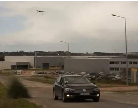
4.3 Virtual tether
Current work focuses on validating the development of the virtual tether mechanism in mapKITE. We enhance standard “follow-me” functionalities of actual open-source autopilots by including continuous operation in presence of gaps in the TV navigation input and robustness against potential outliers. In addition, the virtual tether shall enable on-the-go definition of the UA position with respect to the TV to have full control over mapping performance and mission safety. For example, lowering altitude to increase GSD, increasing altitude to avoid overpasses, fly on the TV sides for particular inspection, etc.
Figure 4 shows the Spyro-4 flying tethered to a car in a recent test performed on February, 18th 2016 at UAVision premises. A simple GPS-based navigation system was used on the car and input to the GCS.
5. PRELIMINARY CONCLUSIONS AND FURTHER WORK
We have introduced the tandem terrestrial-aerial geodata acquisition concept mapKITE for 3D mapping of corridors. Currently, mapKITE is also a system under development sponsored by the European Union H2020 programme. In the frame of this project, among other, the unmanned aircraft, a Galileo dual-frequency receiver, a target detection, measuring and tracking subsytem and the post-processing orientation-calibration software subsystem are being developed. Preliminary versions of the mentioned developments are available and simulation-based analysis of the potential of mapKITE for GCP-less or almost GCP-less have already been published.
In mid 2016, the first mapKITE campaign will take place with the full tandem UA-TV system, using the integrated sensors and systems described along this paper. The campaign will take place at the BCN Drone Center in Moià, Barcelona
(www.barcelonadronecenter.com), featuring 2500 ha of
segregated airspace for conducting UAS research, teaching and testing. A short rural road within the premises will be flown with mapKITE. GCPs and Ground Check Points (GchPs) are currently being surveyed on the road and its neighbourhood.
By March 2017, the H2020 project will be finished and a prototype at the Technology Readiness Level (TRL) 7 (system prototype demonstration in operational environment) shall be available.
ACKNOWLEDGEMENTS
The research leading to these results has been funded by the Eu-ropean Union (EU) Horizon 2020 Programme under grant agreement no. 641518 (project mapKITE, www.mapkite.com) managed by the European GNSS Agency (GSA). The participants of the mapKITE project are: GeoNumerics, Altais Cartografía y Urbanismo, CATUAV (Spain), DEIMOS Engenharia, UAVision (Portugal), EPFL (Switzerland), GRID-IT (Austria), TopScan (Germany), UNESP and ENGEMAP (Brazil).
MapKITE is protected by the Spanish patent 201231200 granted to GeoNumerics, and due patent applications have been already filed for Brazil, USA and the EU.
REFERENCES
Blázquez, M., Colomina, I., 2012a. On INS/GNSS-based time synchronization in photogrammetric and remote sensing multi-sensor systems. PFG Photogrammetrie, Fernerkundung, Geoinformation, Vol. 2012, No. 2, pp. 91–104.
Blázquez, M., Colomina, I., 2012b. Fast AT: a simple procedure for quasi direct orientation. ISPRS Journal of Photogrammetry and Remote Sensing Vol. 71, No. 1, pp. 1–11.
Colomina, I., Miranda, C., Parés, M.E., Andreotti, M., Hill, C., Silva, P.F., Silva, J.S., Peres, T., Galera Monico, J.F., Camargo, P.O., Fernández, A., Palomo, J., Moreira, J., Streiff, G., Granemann, E.Z., Aguilera, C., 2012. Galileo's surveying potential: E5 pseudorange accuracy. GPS World, Vol. 23, No. 3, March 2012, pp. 18–33.
Cucci, D., Constantin, D., Rehak, M., 2015. Smile targets in aerial photogrammetry. Proceedings of the International Micro Air Vehicle Conference and Competition 2015, Aachen, Germany, September 15–18, 2015.
Cucci, D., Constantin, D., Rehak, M., 2016. Accurate Optical Target Pose Determination for Applications in Aerial Photogrammetry. Proceedings of the XXII ISPRS Congress, Prague.
Molina, P., Parés, M.E., Colomina, I., Vitoria, T., Silva, P.F., Skaloud, J., Kornus, W., Prades, R., Aguilera, C., 2012. Drones to the rescue! Unmanned aerial search missions based on thermal imaging and reliable navigation. Inside GNSS, Vol. 7, No. 4, July-August 2012, pp. 36–47.
Molina, P., Blázquez, M., Sastre, J., Colomina, I., 2016.
Precision analysis of point-and-scale photogrammetric measurements for corridor mapping: preliminary results, Int. Arch. Photogramm. Remote Sens. Spatial Inf. Sci., XL-3/W4, 85–90.